My switch draws 0,00A, changed already BQ, MT, PI13 and 77620 no short on the caps, switch does not start. Can anyone point the right direction where to start searching the fault?
Does voltage from the usb c port pass the 0 ohm resistor and reaches the m92t36?
Yes, I have on several Pins on the left side 5V und 2 pins on the top side
my bad misread,
You may want to measure the resistance to ground on 1V8
Just double checking but are you sure that’s ohms and not diode mode readings?
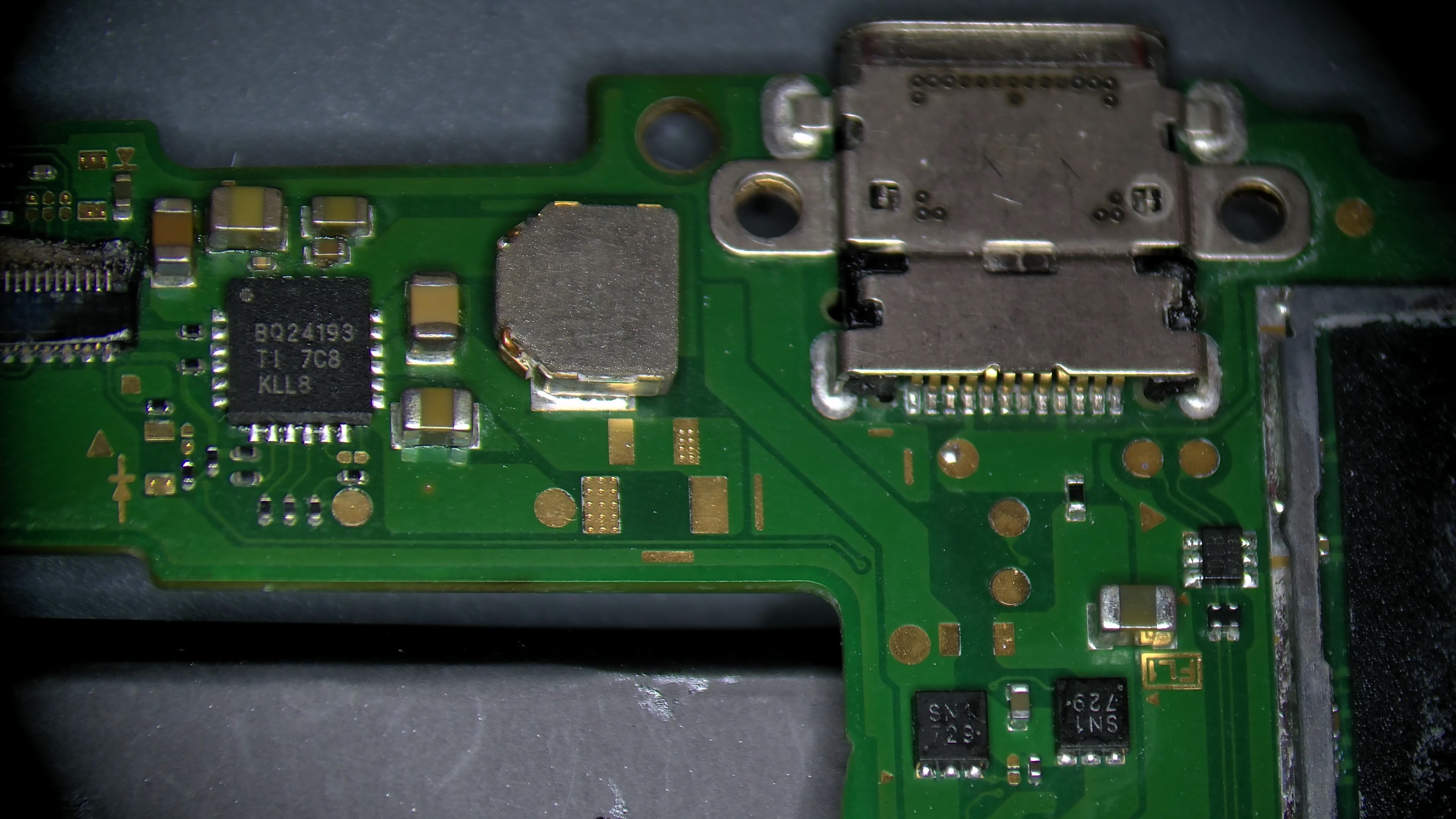
If it’s ohms I’d check the resistance to ground on your SYS rail too, it’s not uncommon for them to go together, you can find this at the large 2R2 coil near BQ, black probe on ground and the other on either side of the coil - doesn’t matter which side
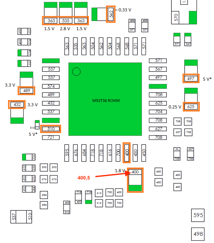
Yes this is really ohms measuring. I have shorted the capacitor before measuring and then it gives exactly 400ohms. Before shortening it was about 390 ohms.
The ohms on the 2R2 coil gives about 1,5 Mohms.
I see, I’d start by removing the EMMC module and seeing if that 400ohm high short clears, if not,
I would proceed to check your other primary rails resistance to ground too at the main PMIC on the rear to see if any of them are shorted also, same thing as before black probe on ground and the other on either side of the inductor, one of these is the same 1V8PDR as above so you’ll get the same 400ohm ish reading, (I made a post recently about this if your not sure where to look) 
Failing that and if this is the only rail at fault, then you’ll probably have to retrace your steps and start removing every majoir IC one at a time which is connected to this rail, hopefully it’s not the SoC 
I removed the EMMC but it is still 400ohm.
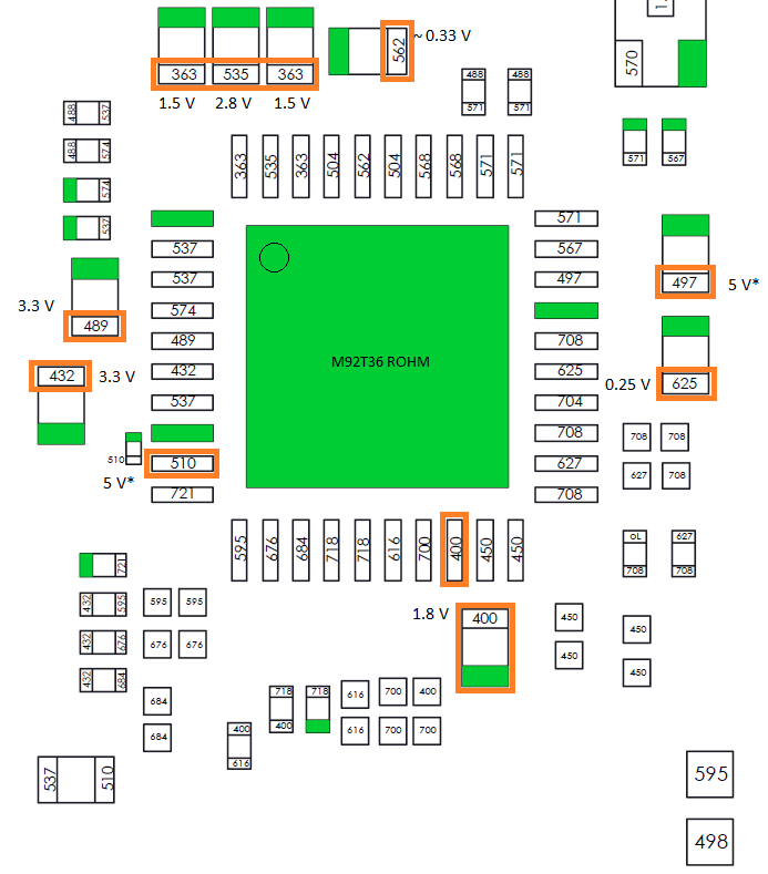
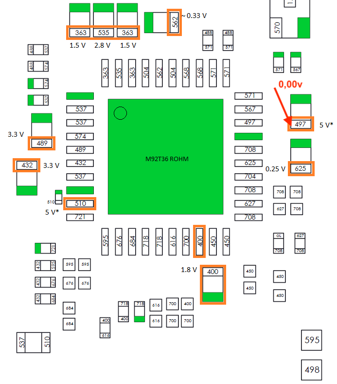
What I understand now is that the 1,8V rail is missing. What I not understand why are the 400ohms high short? In the first picture, all the numbers in the parts means the resistance to ground or not? So there are 400ohm at this part and I got 400ohm why is this wrong? I’m little confused, please explain.
The numbers on Calvins diagrams are not ohm / resistance readings. They are taken in diode mode. The 400 there is a voltage drop of 0.400v.
Thank you for explain. This means red probe on ground and black probe to part. In this case I got 0.39v drop. But this means only that the capacitor is “ok” right?
This is a little bet strange with this capacitor. If I shorten the cap and measure it gives about 400ohms. Take probe down and probe again it starts with above 100kohms and drops to exactly 21,73kohms. Every time I measure it starts on different numbers but mostly over 100komhs and ends up in 21,73kohms. If I wait longer about 2 minutes, first measurement is 400ohms and next measure ends up again in 21,73kohms
Perhaps your meter takes longer to charge the circuit, which is why your reading 400 ohm after shorting the rail to ground and after a while getting something closer to whats expected
1V8PDR is a bit notorious on some meters, if you have another known good board to compare your meter readings against on this rail that might be a good idea and see if you get the same odd results. Regardless a 400 ohm short shouldn’t prevent the consolel from starting but it may be pointing to another issue if this is indeed the potential fault. I think based on you changing the Main PMIC (77620 ) that’s likely the reason for your missing 1V8PDR, I would verify this by measuing the voltage on the other PMIC rails and then after disconnecting power and measuring the resistance to ground at these rails
Could also be an M92 Issue I suppose and it’s not being prompted to boot with USB, so I would manually prompt the console to boot with the power button and see if you measure 1.8V at the spot previously mentioned
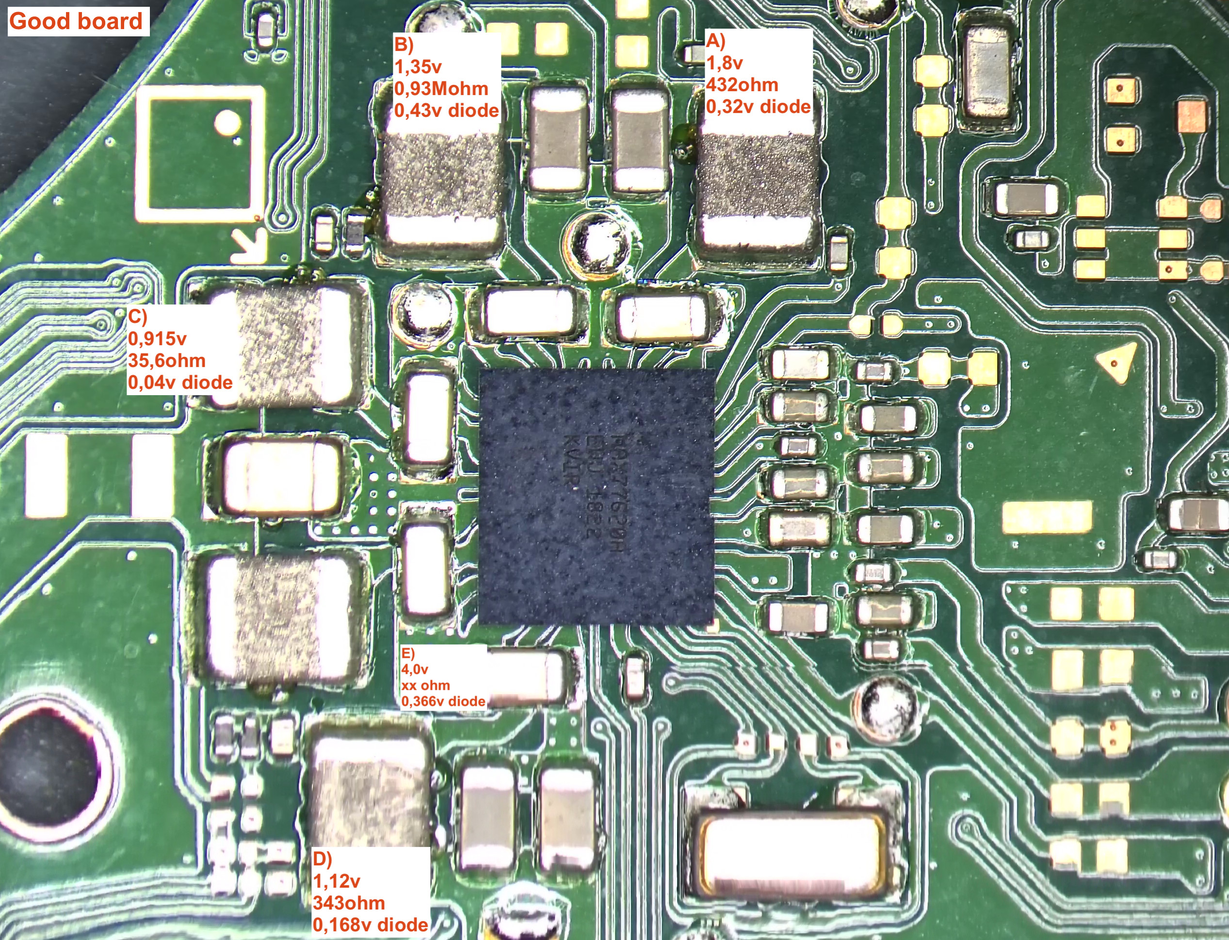
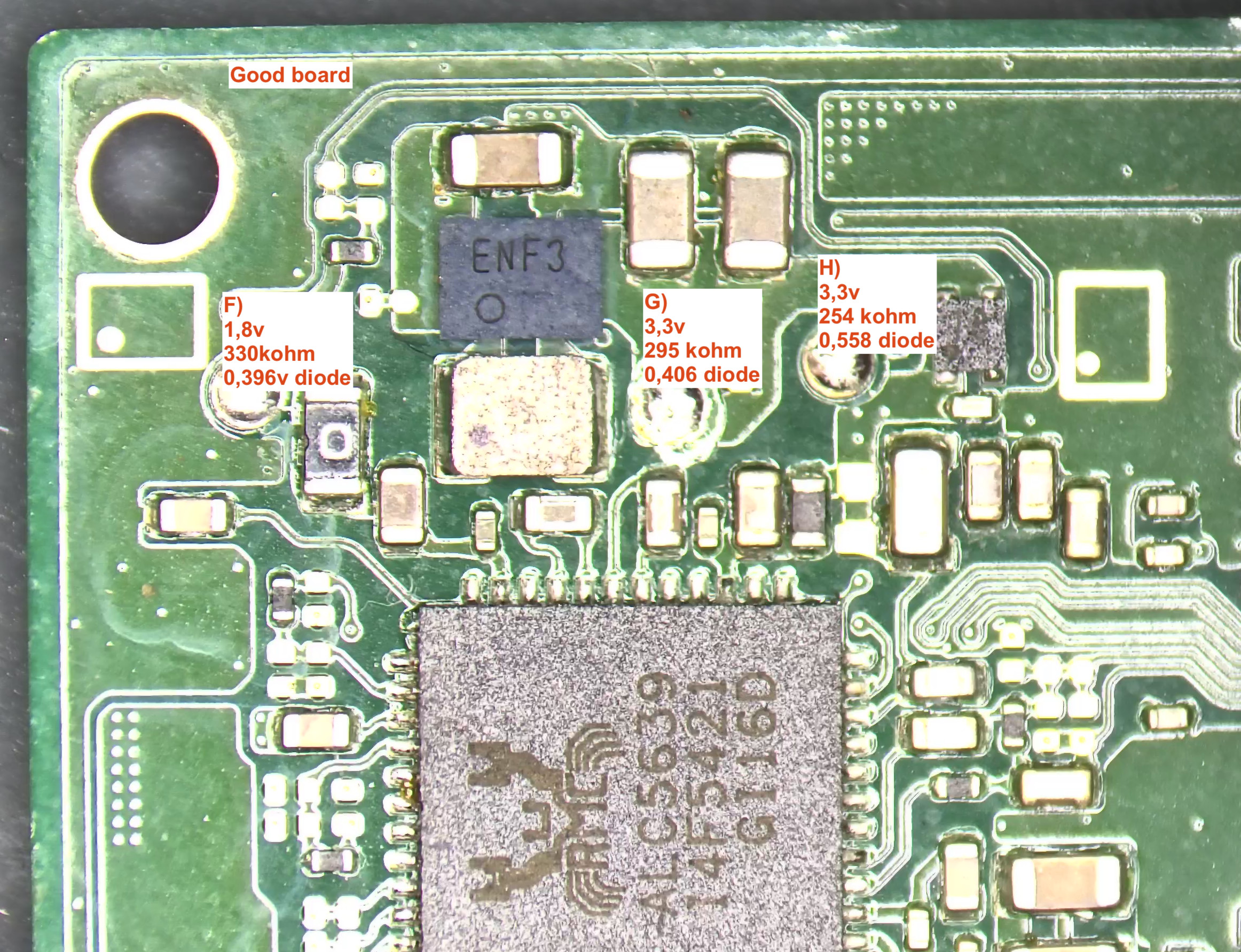
I took today some measurments from a working board see both pictures.
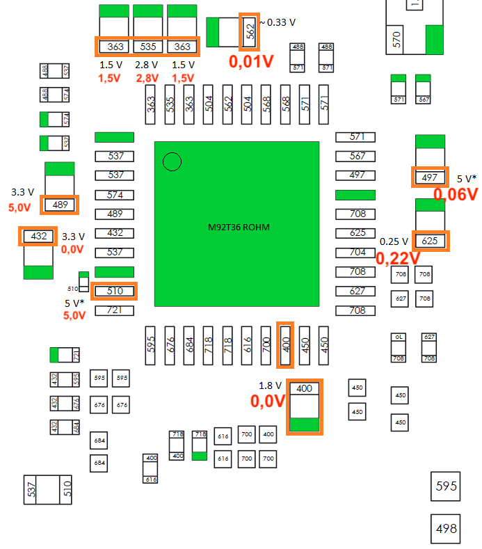
The readings on the faulty board are:
From point A to D the voltages are 0,00v Point E is 3,8v. It think E is battery voltage or so?
A)
0,00v
403 ohm
0,377 diode
B)
0,00v
0,89 Mohm
0,43v diode
C)
0,00v
33,5 ohm
0,04v diode
D)
0,00v
344 ohm
0,166 diode
E)
3,8v
Cannot measure this fluctuating same on working board
0,354v diode
Second picture:
F)
0,00v
335 kohm
0,386 diode
G)
0,00v
53 kohm
0,44v diode
H)
5,00v
247 kohm
0,574v diode
It is interesting that point H have 5v not 3,3v and point G have 0,0v. What does this tell us?
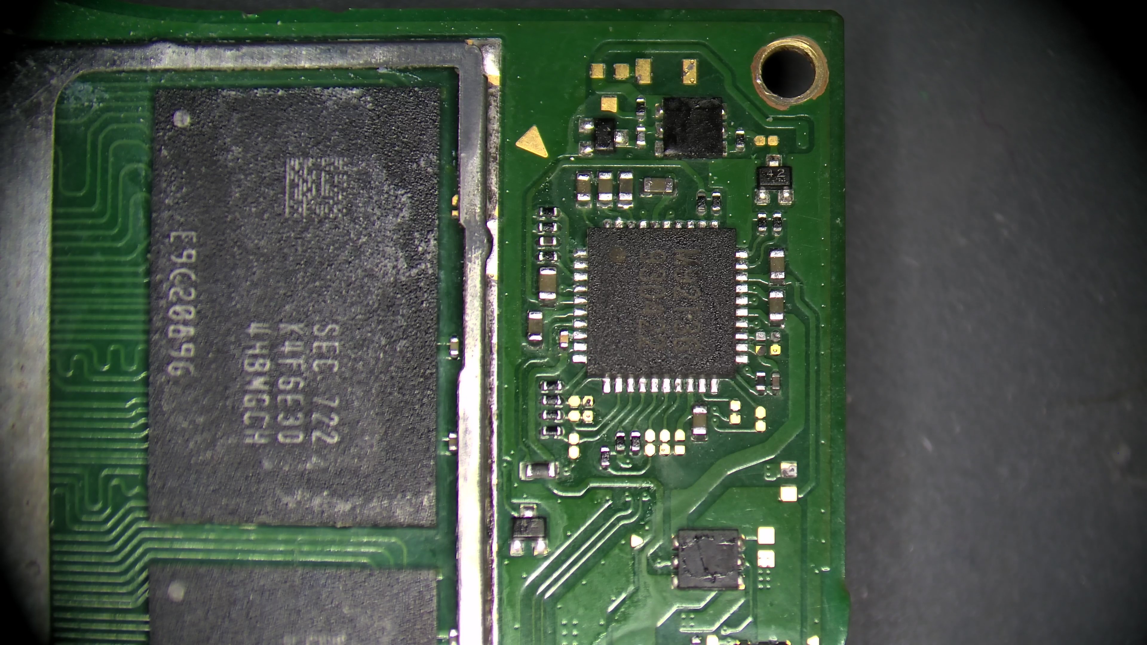
I have also measured resistance on the point around M92, this is on good board and faulty board around 400ohm. So this looks like it is ok.
What chip is producing the 1,8v and the 3,3v? Where does it come from? Any suggestions?
Point E is your SYS rail and it’s fine. Your other rails resistance readings are fine on quick glance, your readings on 1V8PDR (point A) are comparable to your known good board so we’ll assume it’s fine.
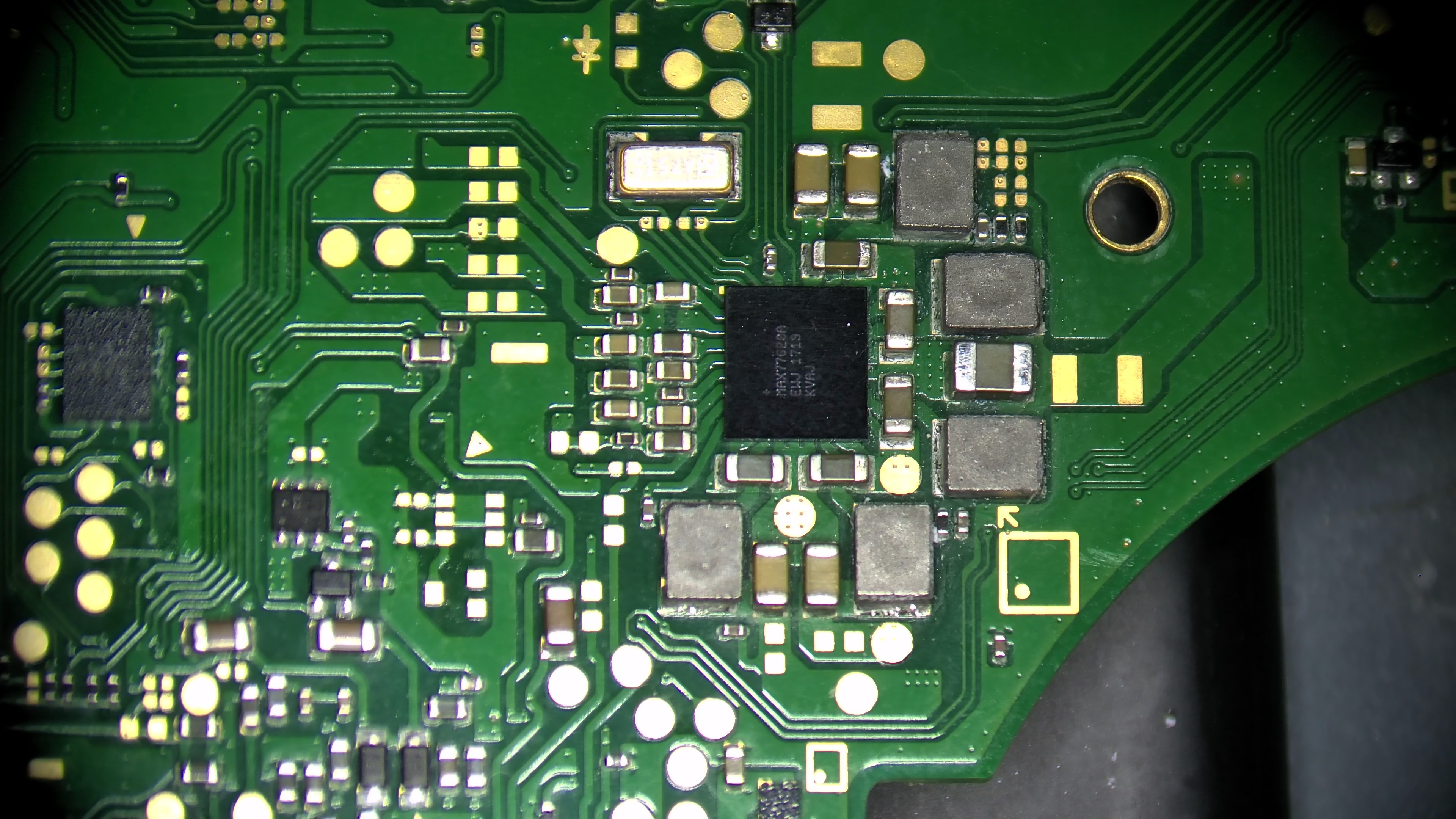
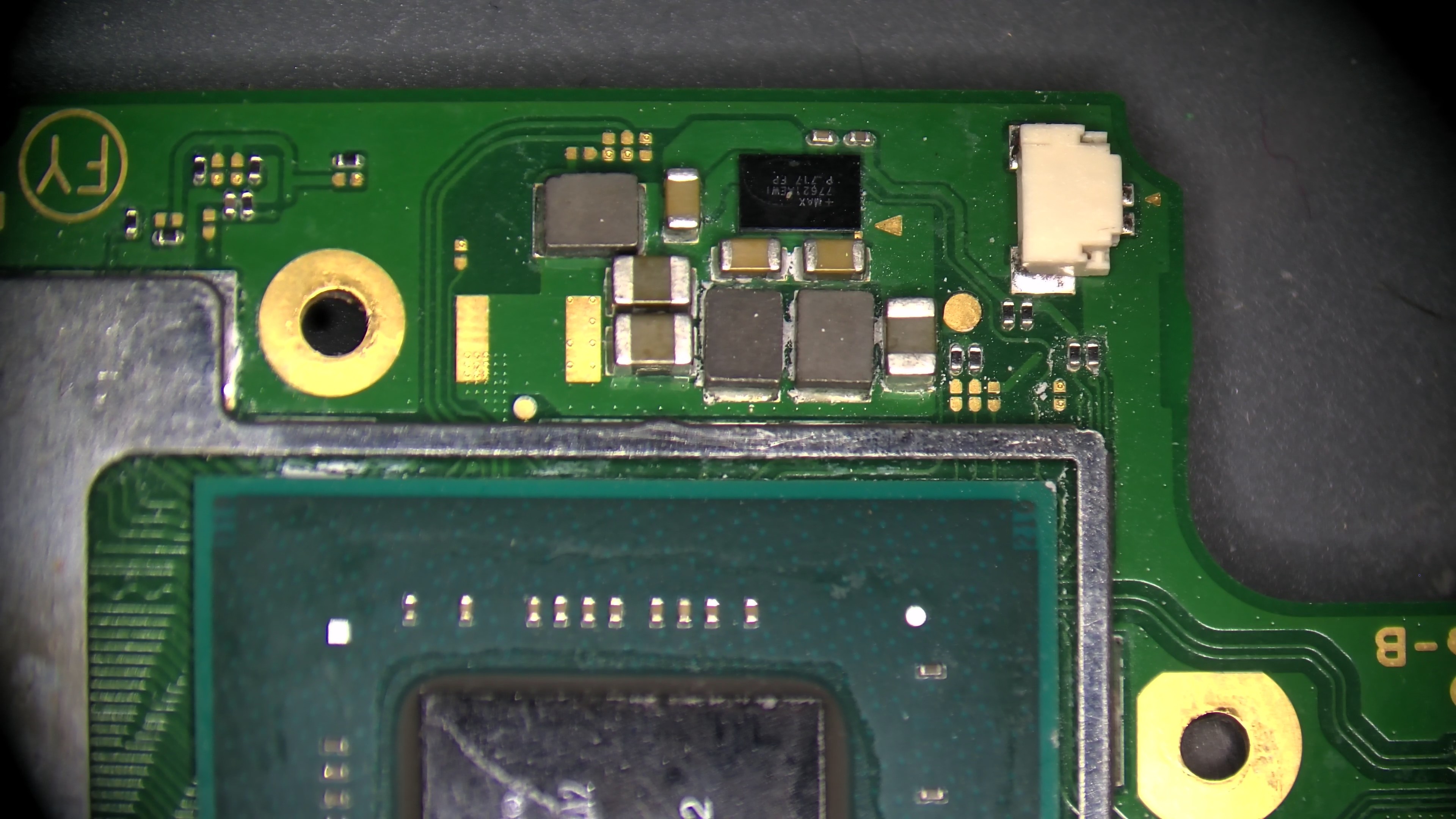
the Main PMIC (MAX77620) produces 1.8V (1V8PDR - point A in your image) the ENXX (ENF3 in your image) produces 3.3V (3V3PDR). You won’t get 3.3V without your 1V8PDR because the enable is 1V8 referenced on the enable, so don’t chase your tail on this one ![]()
As your not getting any of the critical rail voltages at the main PMIC it means either the console is not being prompted to boot or the rails are not being enabled due to an unrelated issue. When you took these voltage readings on the bad board did you prompt the console to boot with the power button flex (or tweezer in the connector?) - as if you are relying on connecting a USB to prompt the console to boot and if you have USB or M92 issues then this may be the underlying issue.
Also you mentioned you replaced the PMIC MAX77620 can you talk me through your reball process?
This was a good hint @Severence ! When I press the power button all voltages are present from A to H! Even on the other side around the M92 all voltages are present as in calvin’s picture showed. But console still 0,00A drawing and not booting. Only one voltage is missing, the 5V on the right side around the M92.
For the MAX77620, I did not reball this, I bought a new one with balls. In my opinion it is not easy to solder back this IC, I recommend a preheater.
What can we do now?
I would connect a charged battery (or charge the battery up externally) and hook it up to a display (check you’ve got no bent pins in the LCD connector) and press the power button and let me know the results.
I suspect you have bad USB or M92 IC (or bad install) or some lines open circuit surrounding perhaps you can take a few photos to verify if you want ![]()
Connected a 40% battery hooked up to the case, but no display no backlight. Changed the PI13 again still nothing. Changed the BQ again also nothing. Voltages are fine, but 0,00A drawing and still missing the 5V on the M92. This is Pin 28 Vex I found out. What is this for and is this an output or input voltage?
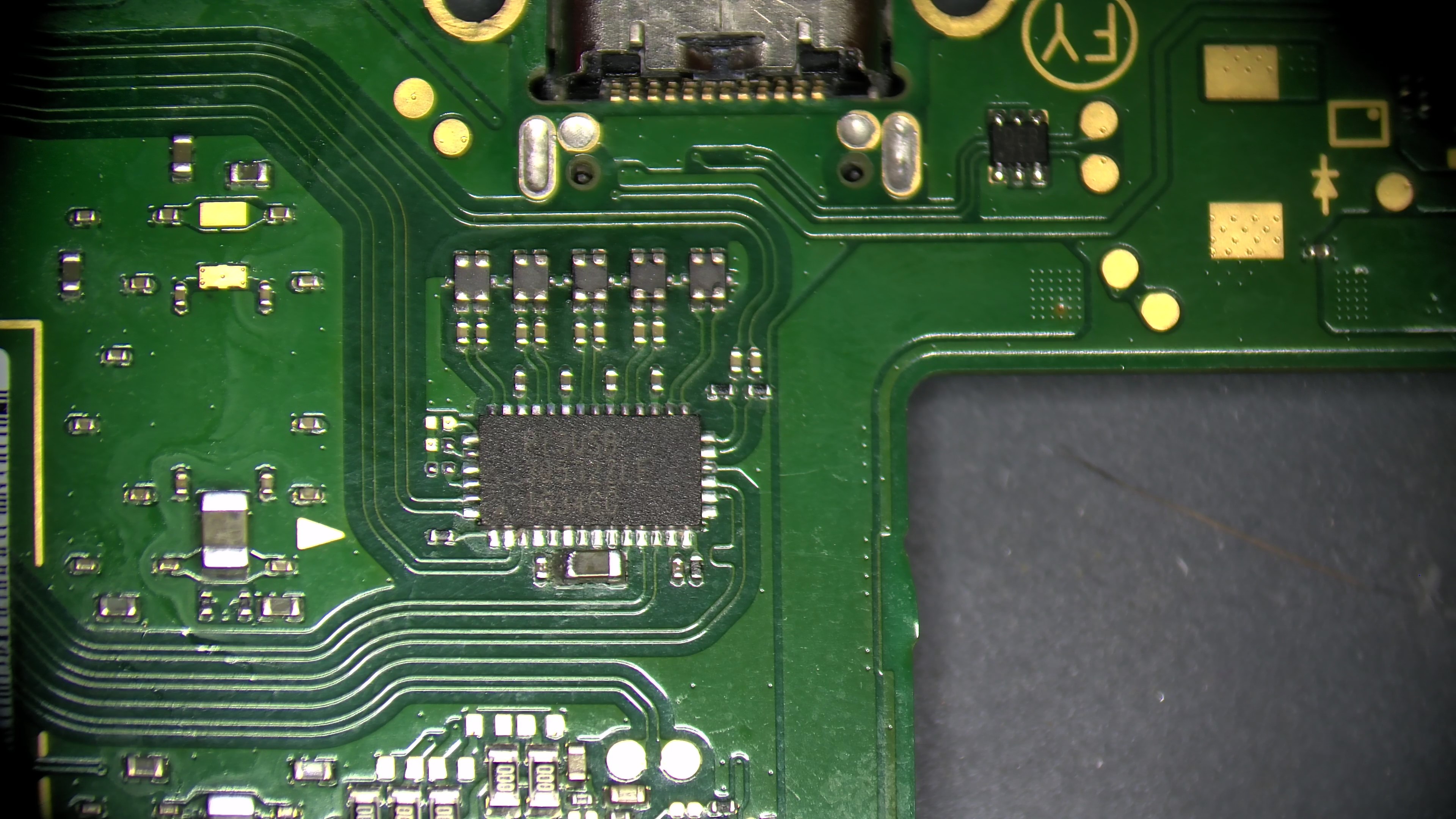
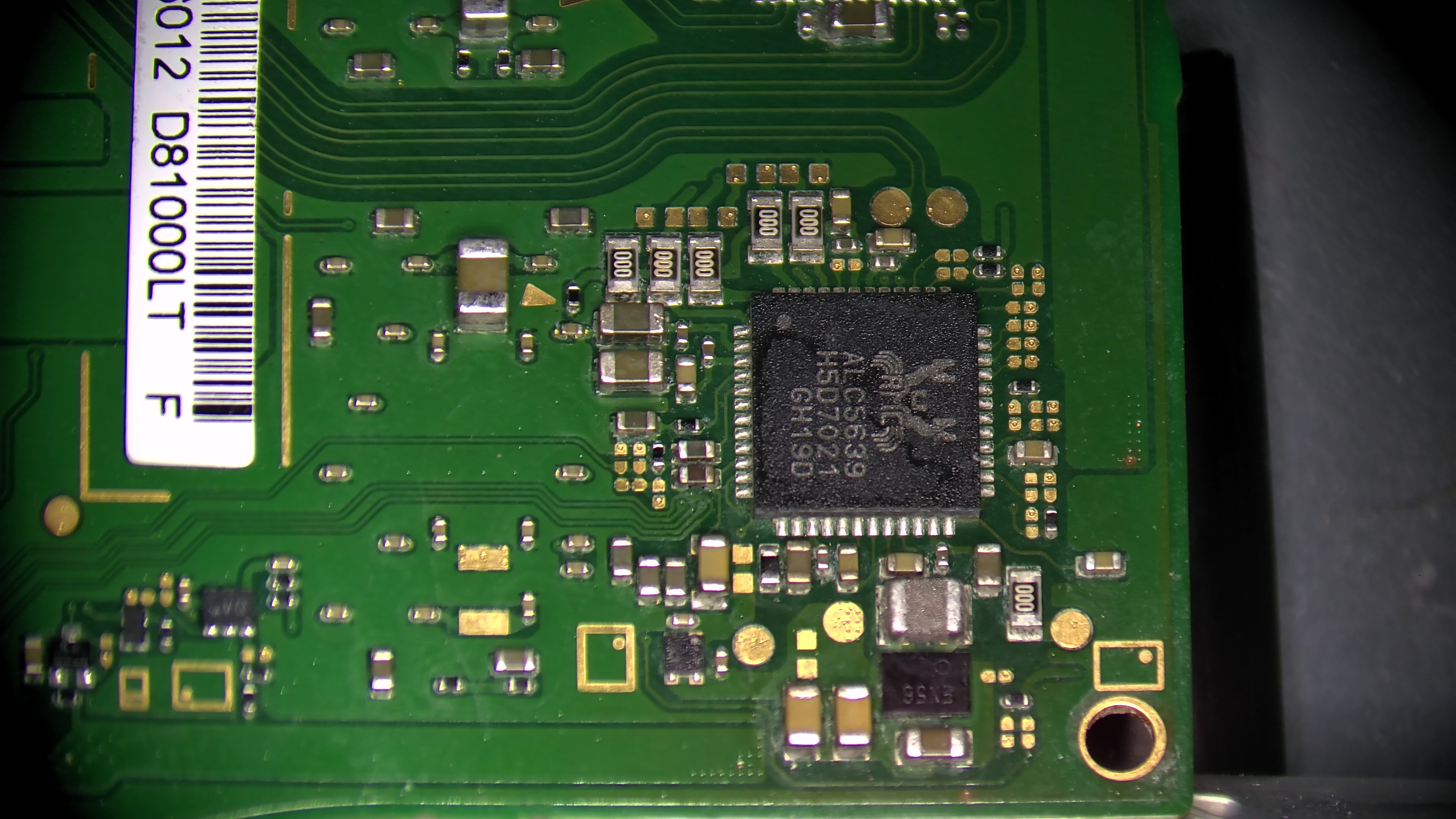
Attached some pictures.