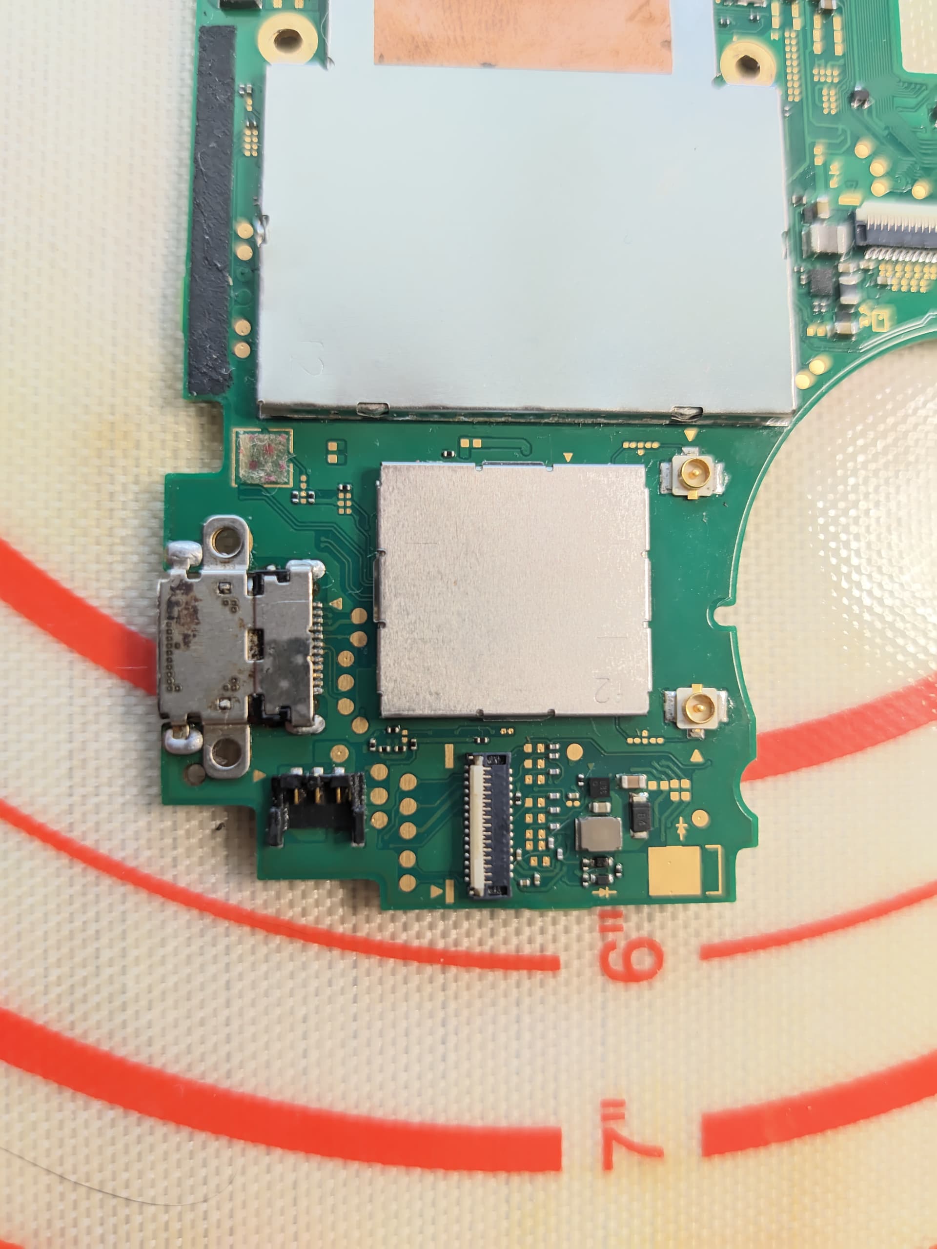
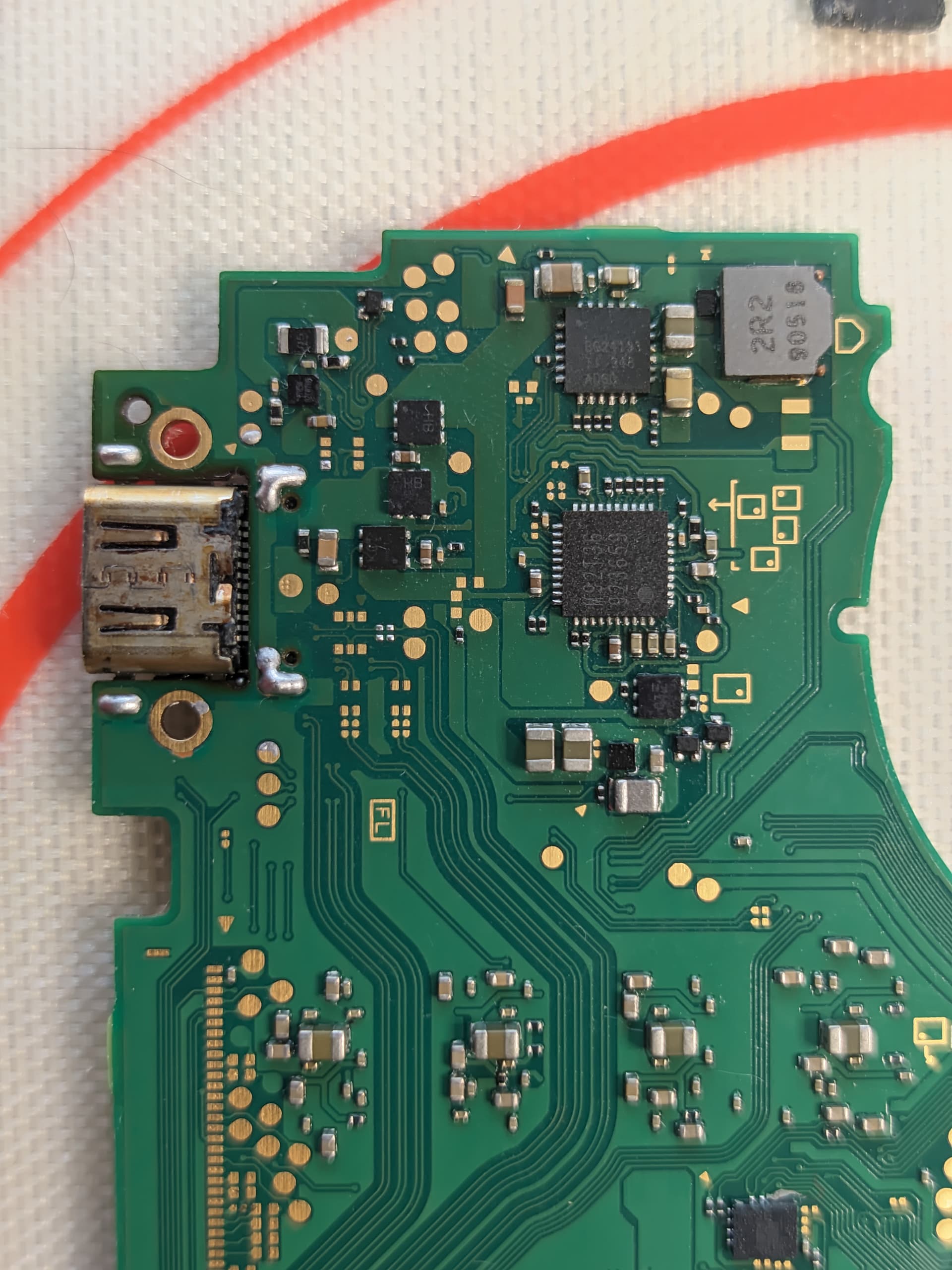
I am new to electronics repair and got a non functional nintendo switch lite from eBay which had a damaged USB-C port. I have replaced the port (and MAX17050 since it flew away while replacing the port) and now it turns on and charges but it has very high battery drain (it will go from 100% to 0% overnight in standby mode).
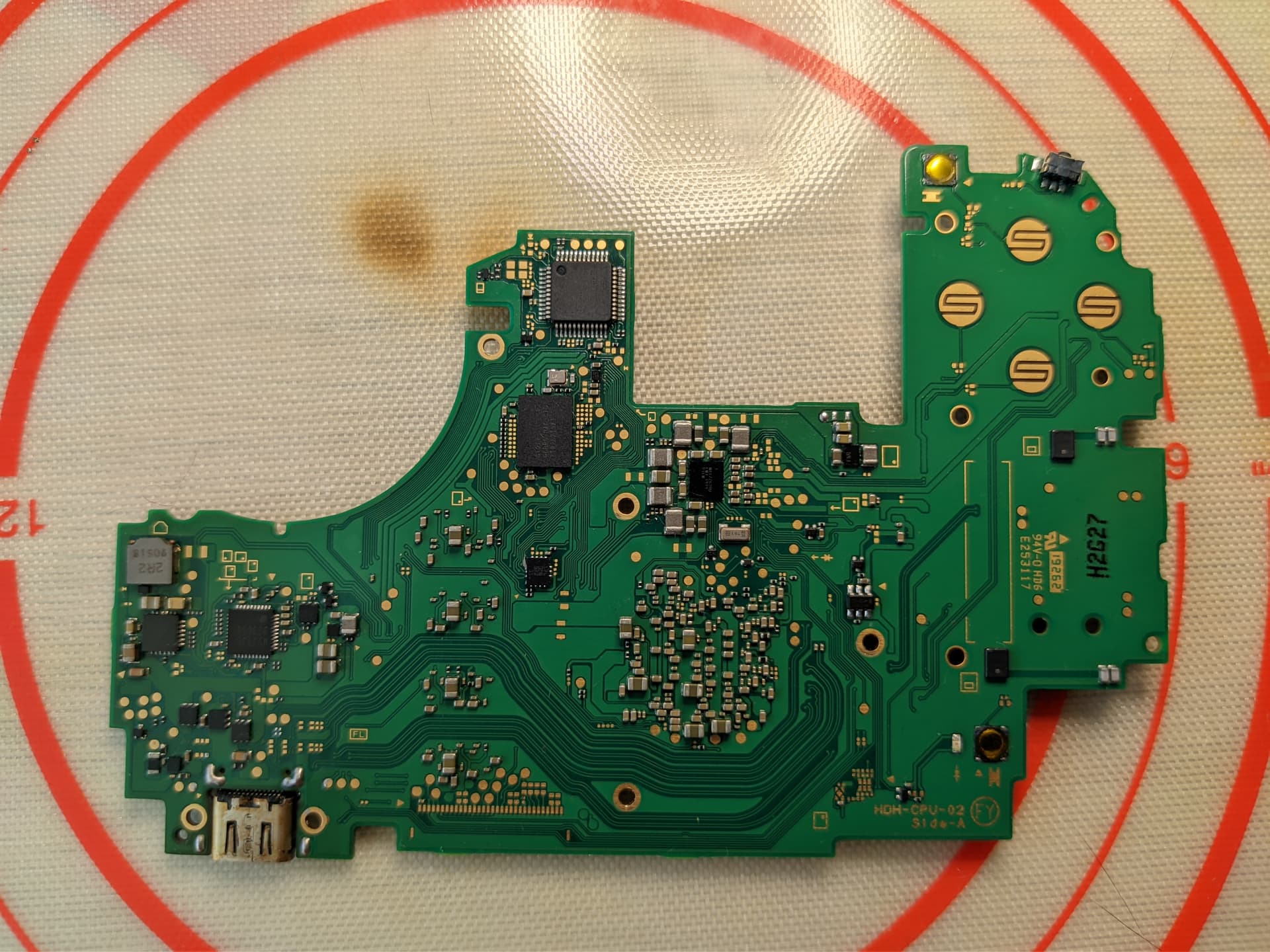
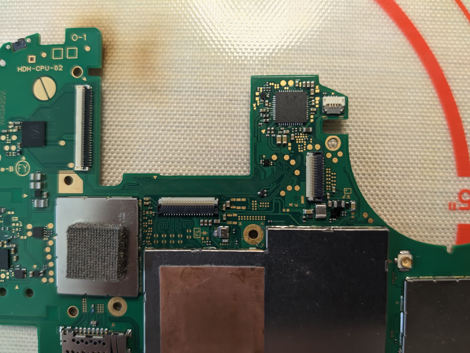
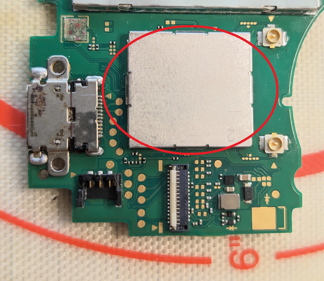
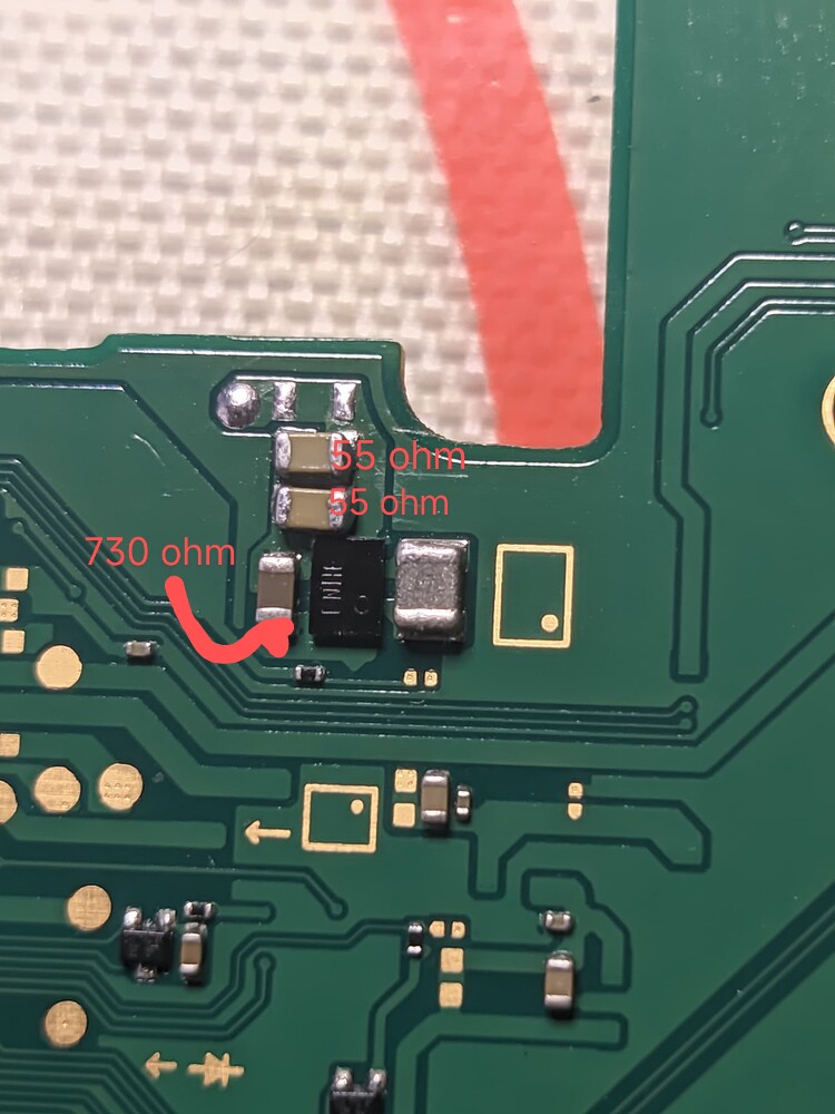
I checked the board again and found that the 1.8v line is shorted. (only 5ohm resistance on cap next to pin 18 on M92T36 chip) and now I am a bit lost. The rest of the caps around this chip show no shorts and normal values.
When plugged in, I can measure 1.8v in this cap. Also found shorts in other caps connected to 1.8v rail.
Could this be an issue from the M92T36 IC? Also BQ readings seem normal according to other threads I’ve read in this forum.
I see. Given that the USB port had issues, it’d probably be wise to pull the M92 IC off regardless, as typically M92 IC will fail in USB bent pin scenario. Then might be worth checking resistance to ground again on 1V8PDR to see if anythings changed.
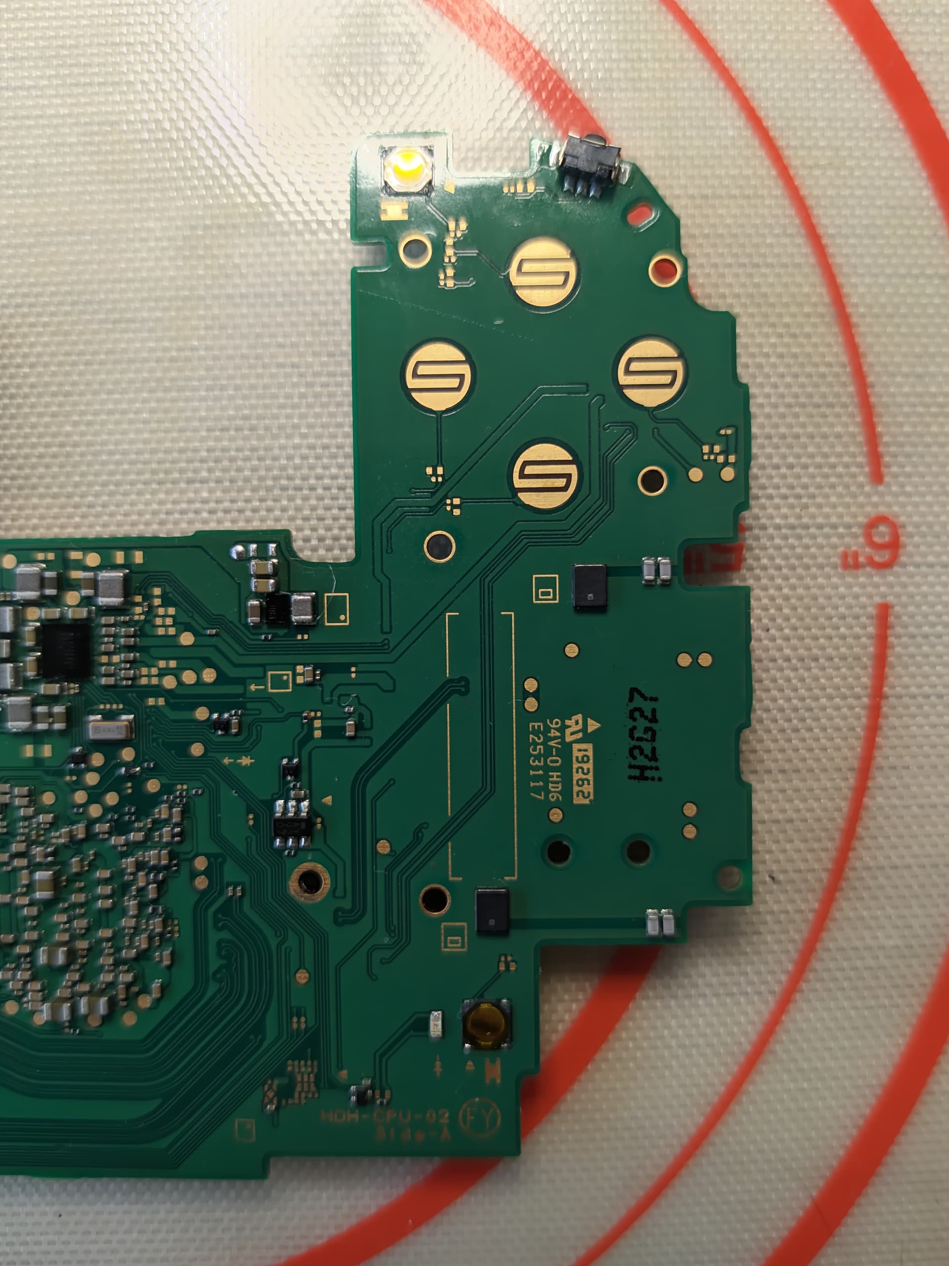
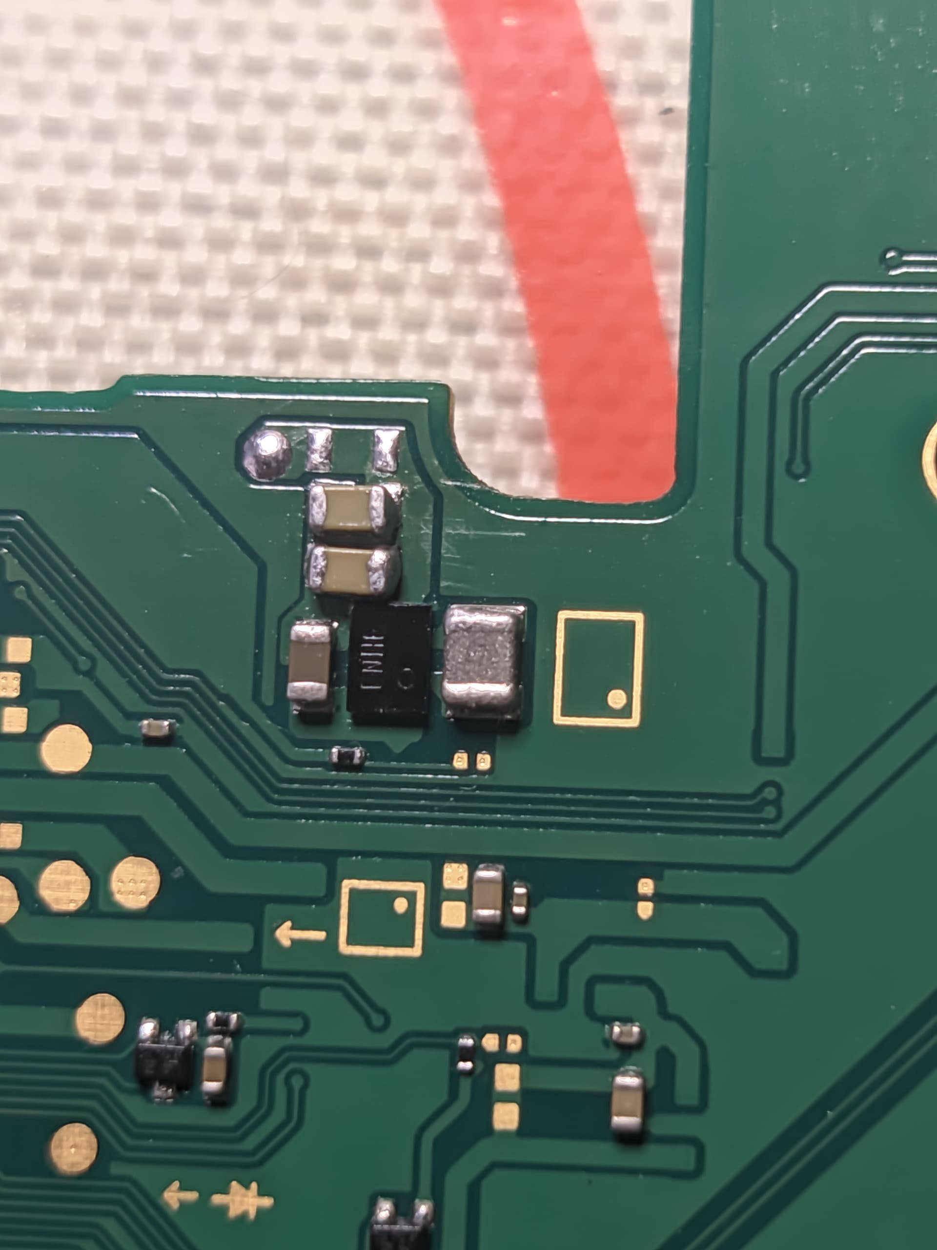
Indirectly, pullup lines. Have a look on edge and see if anything jumps out at you as being wrong.
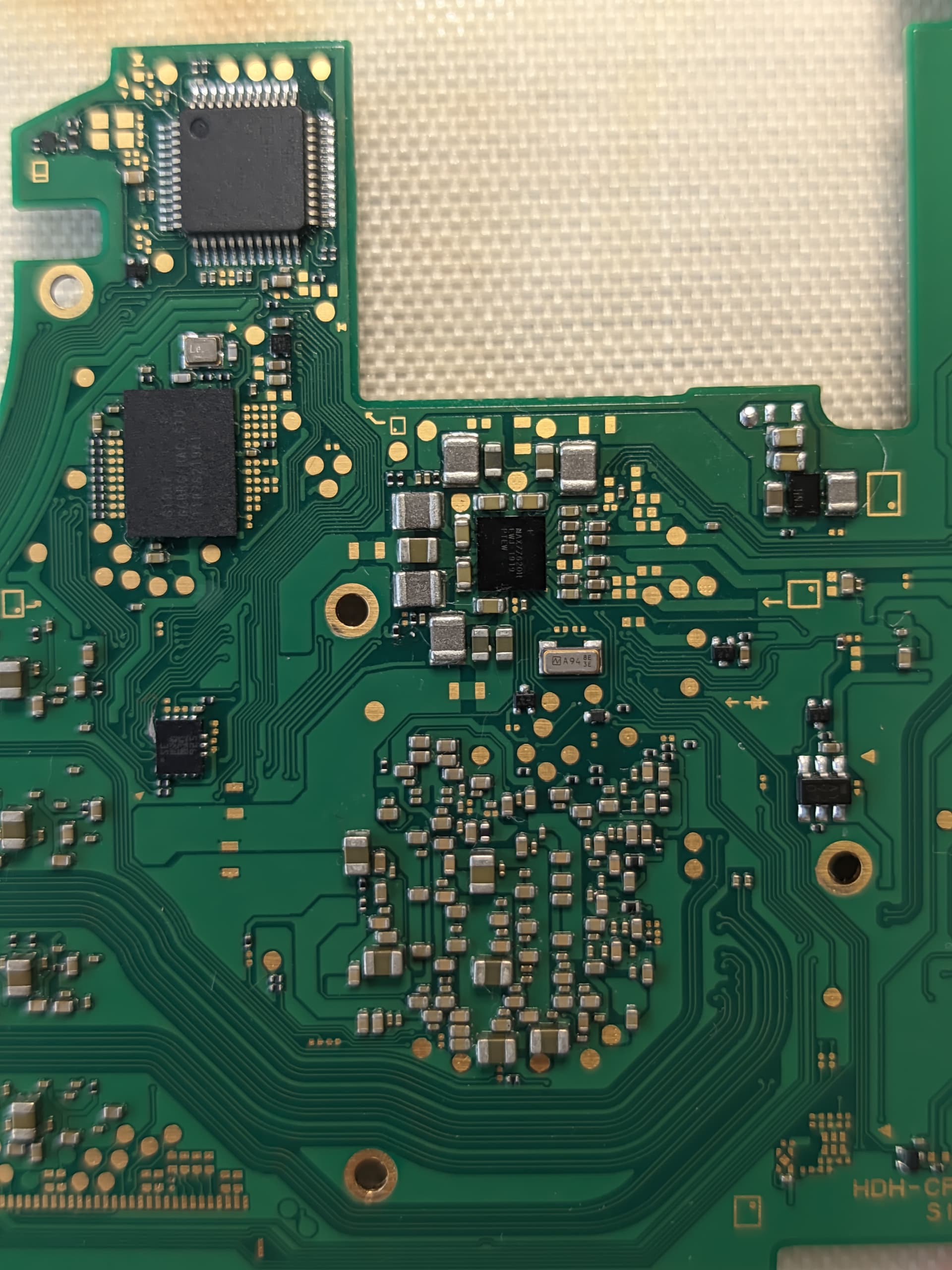
I also noticed, the Fuel gauge IC which was on previously is damaged and will likely not work, so might be worth ordering some more of these (from mouser, digikey etc) for future.
Don’t worry about this just yet. If your reading approx 5 ohms to ground it’s pretty clear cut that somethings up.
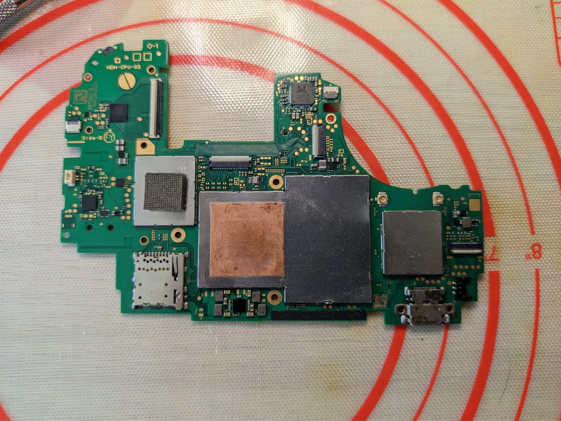
Failing all the above, my thinking prior was perhaps WIFI IC shifted during USB rework due to overheat or minor knock during reflow, but looking at your image nothing looks all that bad and as you didn’t get the readings prior it’s hard to say
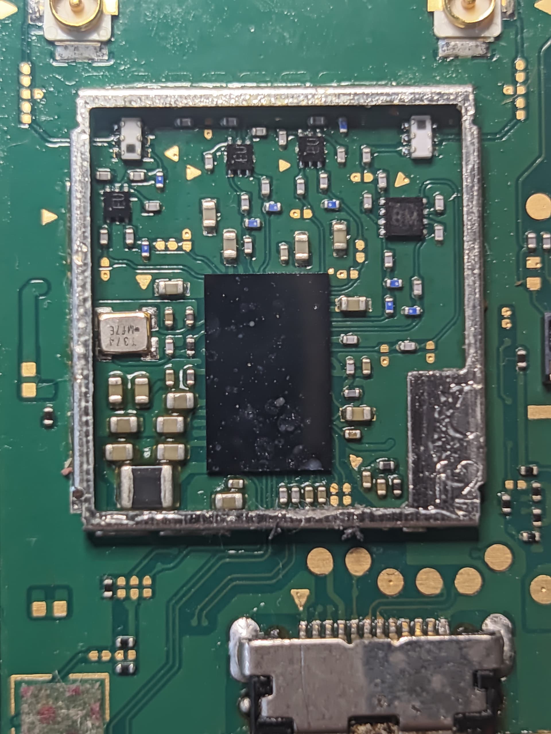
Bad news. Removing M92 IC didn’t fix the short. However, when I tilted the board a little I was able to see some solder balls under the WiFi IC, is it worth to try to reflow it?
I do not have more time to work on it today so I will continue tomorrow with whatever suggestion…
I’ve got some spare MAX17050 already so I could use that in case we can fix it.
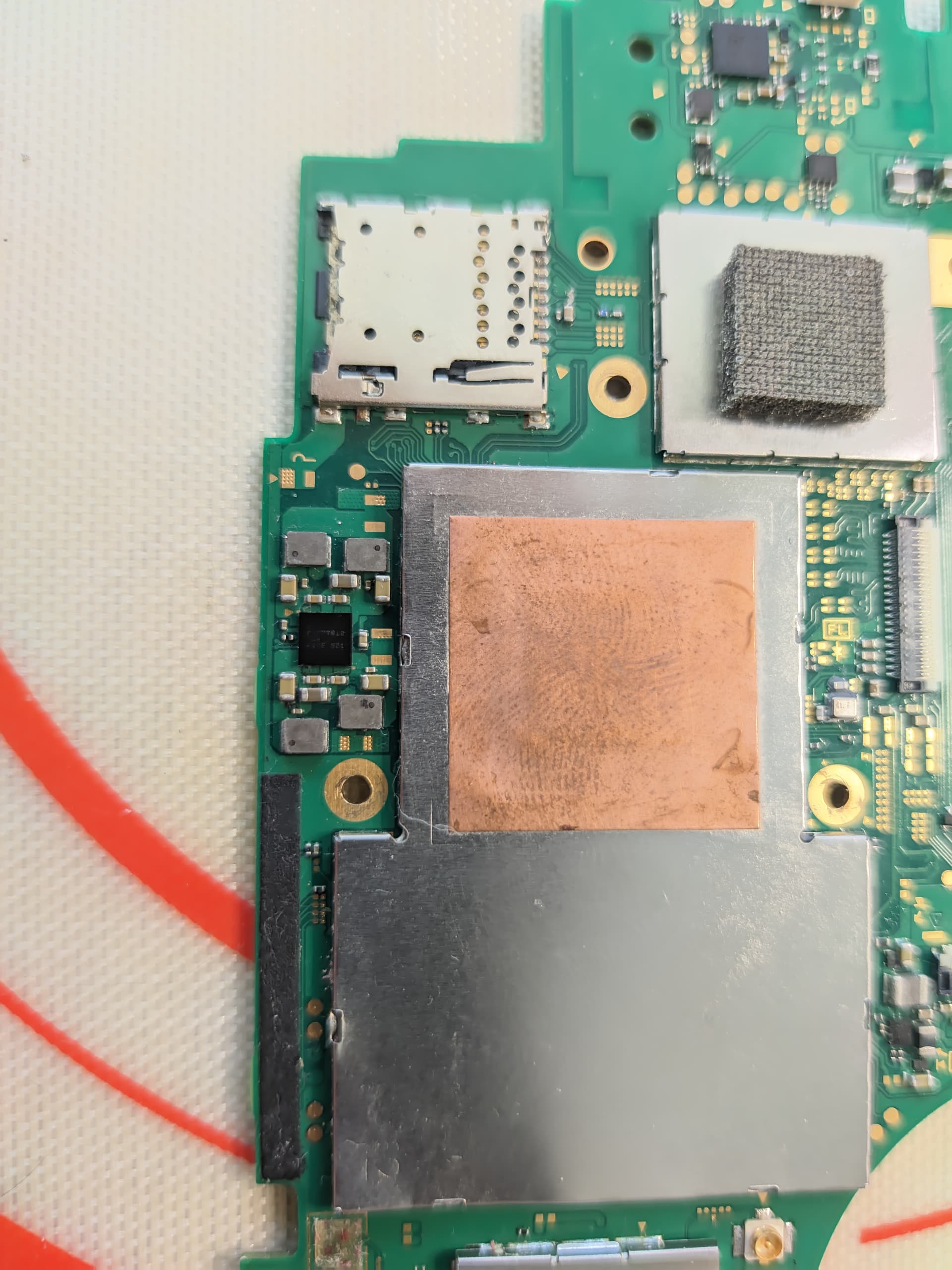
I guess you could hook up a PSU to the shorted rail and see if you can find the culprit via heat… though, I’m not a fan of this method so early on, that, and 5 ohms is going to generate very little heat, particularly if it’s an IC responsible, so you’d be better off maintaining a consistent ground, going round the board at various 1V8PDR locations (approx 5 ohms to ground) and seeing which area of the board represents the lowest reading to narrow it down.
Just before this though, can you also check resistance to ground on the big 2R2 inductor by BQ IC just so i can rule that out. Also resistance to ground on 3V3PDR (caps near EN IC)