I have a Nintendo switch lite I changed the joysticks on. The new joysticks and backlight we’re working after putting it back together, but the ZL button wasn’t. I took it back apart, verified everything looked good and put it back together and now there is no backlight.
I checked the connector pins and the backlight ribbon cable on the daughter board and they look perfect. I tried another left daughter board and still no backlight. I bought a new ribbon cable that connects the daughter board to the main PCB and still nothing. I even looked at those connectors under a scope and see no issue. If I shine a light on the screen I can see it and I hear sounds, but the screen is just not lighting up.
I checked the caps for shorts around the backlight BGA chip on the main PCB and see no shorts and diodes check good. Maybe some has diode readings in this area I can verify? I’m at a loss at what could be causing the issue. I wonder if the backlight BGA is bad even though it shows no shorts around it.
Thanks for the reply. The connectors look good on both sides. Would you happen to possibly have diode readings to make sure they are fine? Or maybe another method other than just looking to verify they are actually good? Just trying to find another way of checking them since they look fine.
I don’t know what else method would better than diode reading.BTW the pic you referring is from me.
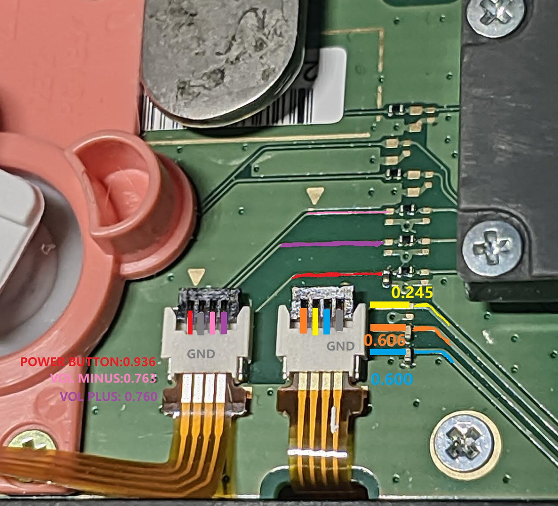
Disconnect battery and leave everything else connect, measure diode reading from backlight connector
Is it possible to short something if the battery is unplugged? As soon as I open it, I unplug the battery. I’m going to try and get some diode readings on the connectors tomorrow in hopes someone has diode readings of a working switch lite to compare. Thanks guys.
With the battery disconnected and everything else connected, including ribbon cables. Checking the backlight connector and going based on your picture, orange color pin I get 0.411, yellow pin I get OL, blue pin I get 0.411 and last pin I get 0.000 ground. This was with red probe on ground and black probe on the pin. Pretty obvious based on your picture and what I get it’s way off.
Based on the numbers, what does this tell us other than there is a problem? Does this tell us there is a problem with the backlight or if the problem is coming from the main PCB?
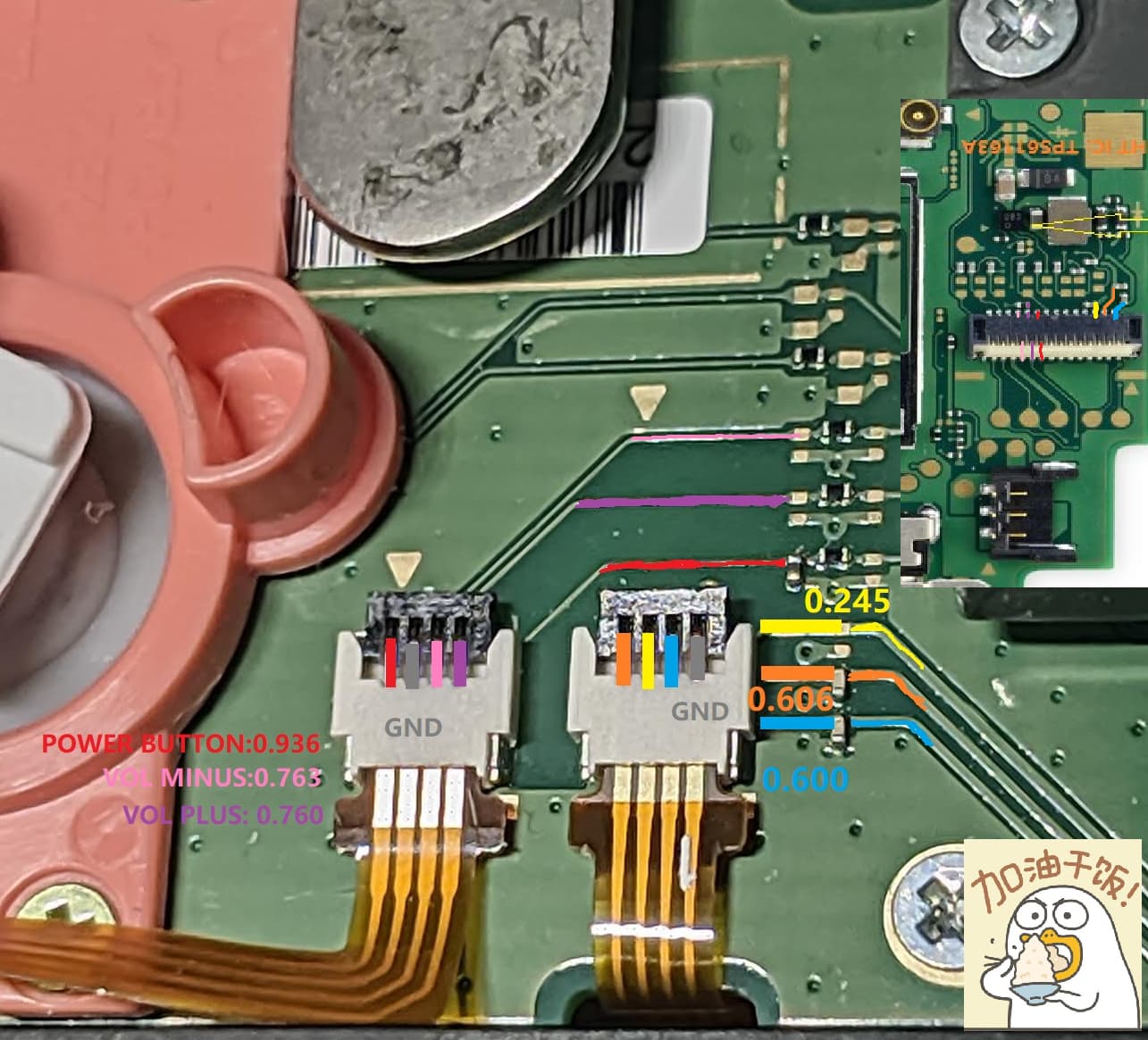
Check the continuity of the yellow line from daughter board to the mainboard small cap. Your reading is a bit off from mine but maybe just due to different multimeter
So, I have continuity from the backlight ribbon cable going to the yellow pin and the via right after it in your picture. However, it seems I don’t have continuity from the via to the main connector at the bottom that goes to the main PCB. I have a backup PCB that does have continuity from the via to the main connector, but the connector is bad. I’m going to attempt to remove the connector from this bad daughter board and solder it to the one that does have continuity. Hopefully this is the issue and I’ll report back. Thanks!
So, I forgot my son had his old switch with a cracked LCD, but I was able to see the backlight turn on. I took the small daughter board from that switch and put it into my wife’s switch… SUCCESS! Backlight turns on and all buttons work perfect. Thanks for helping me troubleshoot this guy’s.
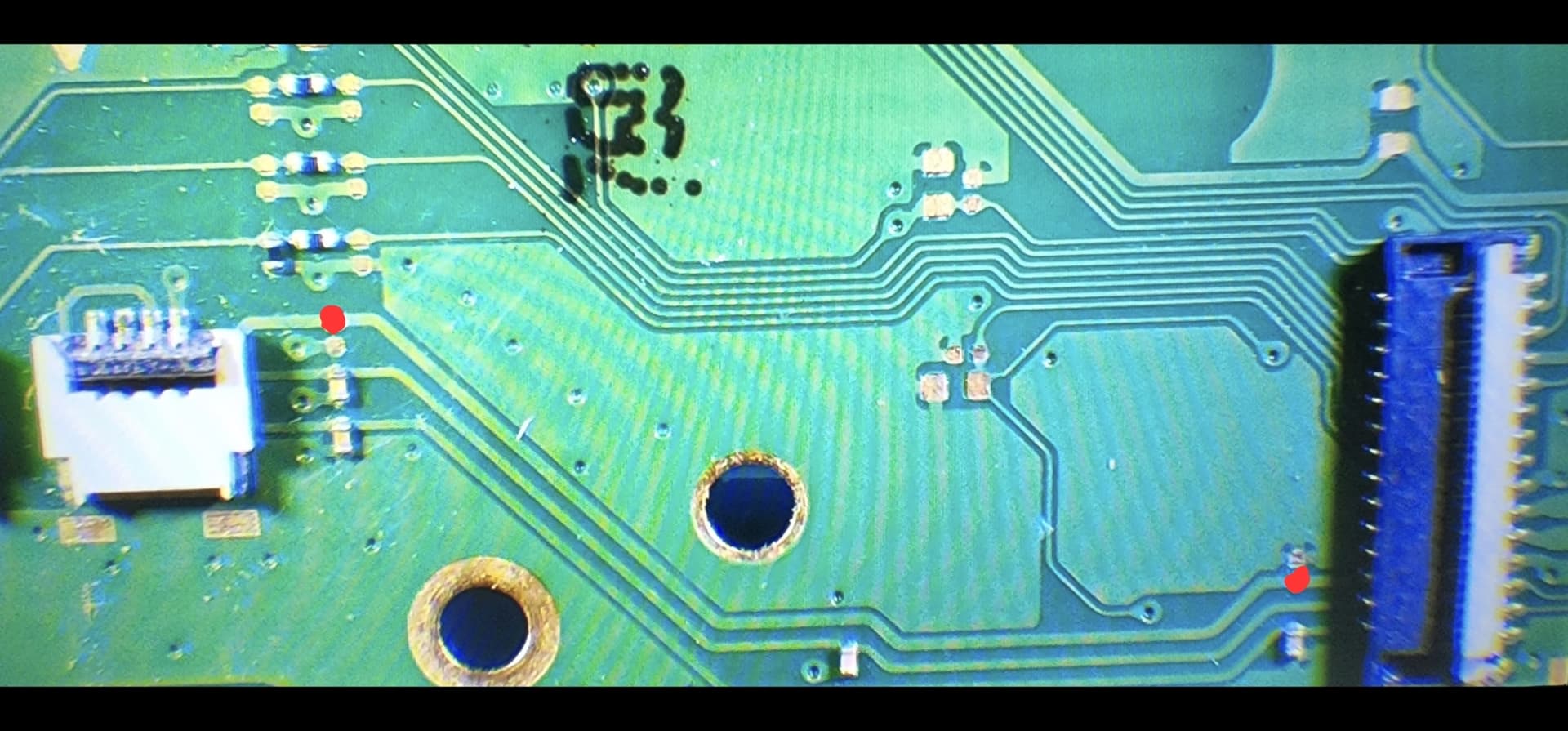
I’m going to take a pic later showing the points where I didn’t have continuity so other can troubleshoot. It’s the test pad right after the backlight connector and the test pad before the large connector that goes to the main PCB. I’m confident that even if I changed out the connector, it wouldn’t have mattered due to the break in continuity before the connector. I don’t see any damage between those test points. It’s as if the trace separated between the 2 points for some reason.
I would like to figure out what happened to the original if I can. A simple jumper wire might have fixed the issue, but I didn’t have the right size wire.
I don’t recall plugging in the flex cable after plugging in the battery. I also agree it’s much safer to plug in the battery at the very end and is what I normally do.
Is it possible for a trace to completely separate from this?
Just wanted to make an account to let you know this picture saved my switch , I also didn’t have continuity at these points
I soldered to the top of the cap above the 9 ball chip (the small square one) as it’s 17v, across the battery to the other board to the trace of the two points you highlighted
Using a multimeter pressing any of the red points you show and then any area that gives 17v the screen would light up , I was estatic thank you!
Now to replace the ribbon cable again because now the left d-pad isn’t working and I’ve no idea of any pin out to fix that
Thanks again !
Also glad you fixed the switch even if it meant taking from your son’s broken one
Sweet deal and you’re welcome! Glad I took the pic in case others came across this issue. In all honesty @jkyoho pic with diode readings helped. Without any damage to the trace, I probably would have never checked for continuity there. Seeing OL on the yellow pin where I should have gotten a diode reading I guess was the nail in the coffin. Odd that yours had the same issue. Still never figured out how or why it happened. Bad batch of boards with a weak trace?
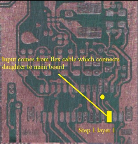
I had an issue with the left d pad not registering and I traced the fault from the daughterboard all the way up to the STM chip. Anyways, the above photo is from the FPC connector on the main logic board that connects it to the daughter, what’s highlighted in yellow is where the signal from the L D-pad comes in from the flex cable.
If you can’t find a fault in the flex cable, test for a short on the highlighted pad. Chances are its the flex cable, but if not then the STM chip the FPC connector would be the next two culprits