I’m pretty new to this soldering stuff so go easy on me. I had a switch lite that had a visibly damaged USB-C port so I replaced it. Nothing is showing up on my ammeter. I will say that I’ve tried twice now and on the first port that I put on did have solder on the inside set of pins (I didn’t tin them). I’ve checked for shorts on the M92 and BQ and nothing, all seems fine.
Top hot air or bottom hot air? fuel gauge ic picture?
What voltage do you have on pin5, pin6 cap or usb port fuse?
Top Air
https:// prnt.sc/QO2QXiuBIjwR (sorry it won’t let me embed the image)
As for that last set of questions. I don’t know where to take those readings. Would you mind giving me a pic please?
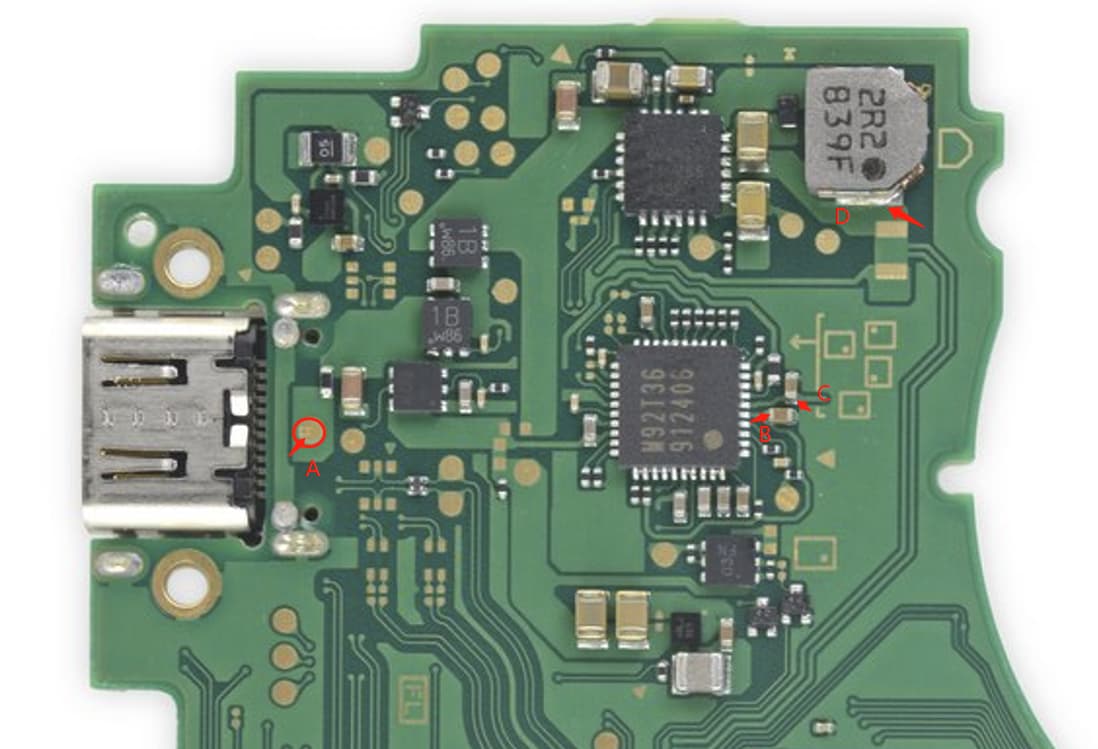
A: 5.22v
B: 5.17v
C: Fluctuates between 2mV and 0v
D: 4.29v
sounds like m92 went bad on you.
replaced m92 and now im getting a reading of ~40mV at C but it climbs and i get nothing at the D point
forget about BorC reading if you not connecting battery.
i should have asked before i made my comment, but by “nothing on the ammeter” do you mean that the ammeter doesnt turn on, or that you are seeing 0 amps?

any shorts showing around the fuel gauge IC highlighted in yellow above?
both sides of the resistor above that IC have cont. to ground. is that supposed to be that way?
Almost forgot to answer your first question. By ‘get nothing’ I mean 0A. I don’t have an ammeter specifically for typeC devices so the only one I have is always on
UPDATE. Took that resistor off and the right side of that resistors’ pad isn’t shorting to ground. replaced that resistor and it shorts out again. i then took off fuel gauge and it still shorts on both sides. with the resistor removed its fine
that’s a current sense resistor i believe if you’re talking about the big guy above the fuel gauge. Its not shorted. If the capacitors around the fuel gauge aren’t shorted then your fuel gauge is most likely fine.
What are your readings on the caps around BQ, the inductor above BQ, and the test pad directly behind the battery connector?
I get the following readings at these points A: 35mV B: 24mV and virtually 0 everywhere else xhttps://prnt.sc/q1eo3Ve-mgI3
Im going to assume you’re talking about this point right here xhttps://prnt.sc/nrV-AhP9LMg4 I get 3.7v
hmm, yeah, not good you should definitely be seeing voltages on all the caps around BQ and especially the inductor. Are you using an official nintendo charger? Only reason I ask is because you list 5 volts on test pad A and if you’re using an official charger you should be seeing ~15v at the same point.

for a sanity check, can you verify the fuse highlighted in yellow above is still good? They rarely blow, but its nice to rule it out just in case.
Any pics of your actual board would be great including some angles of the work you’ve done on M92. I know you replaced it, but there is also a chance you have a dry joint or your replacement is bad.