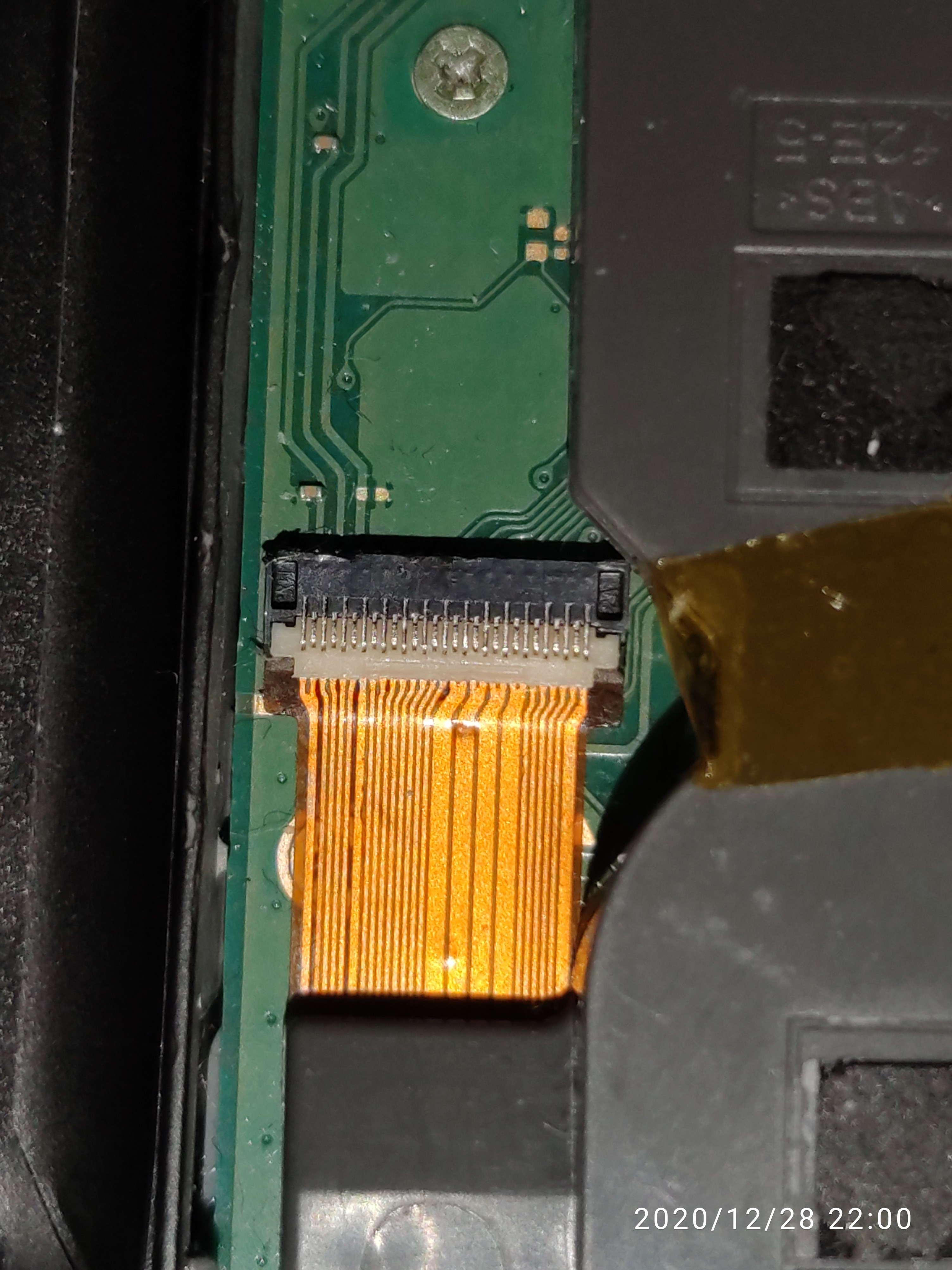
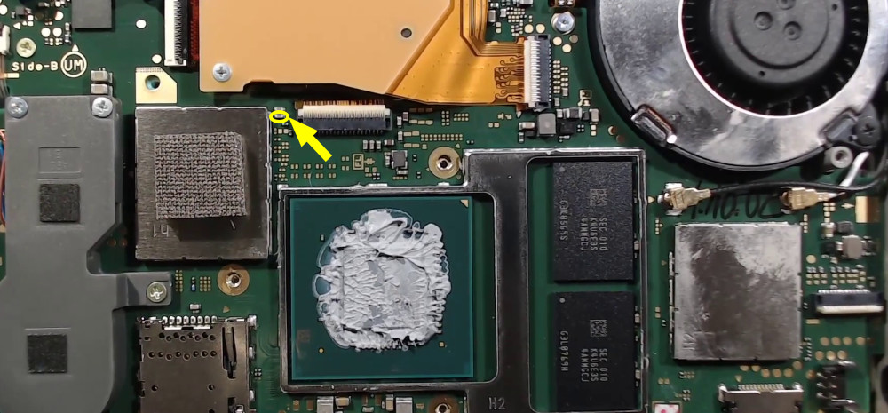
So the motherboard connector was changed( this one)
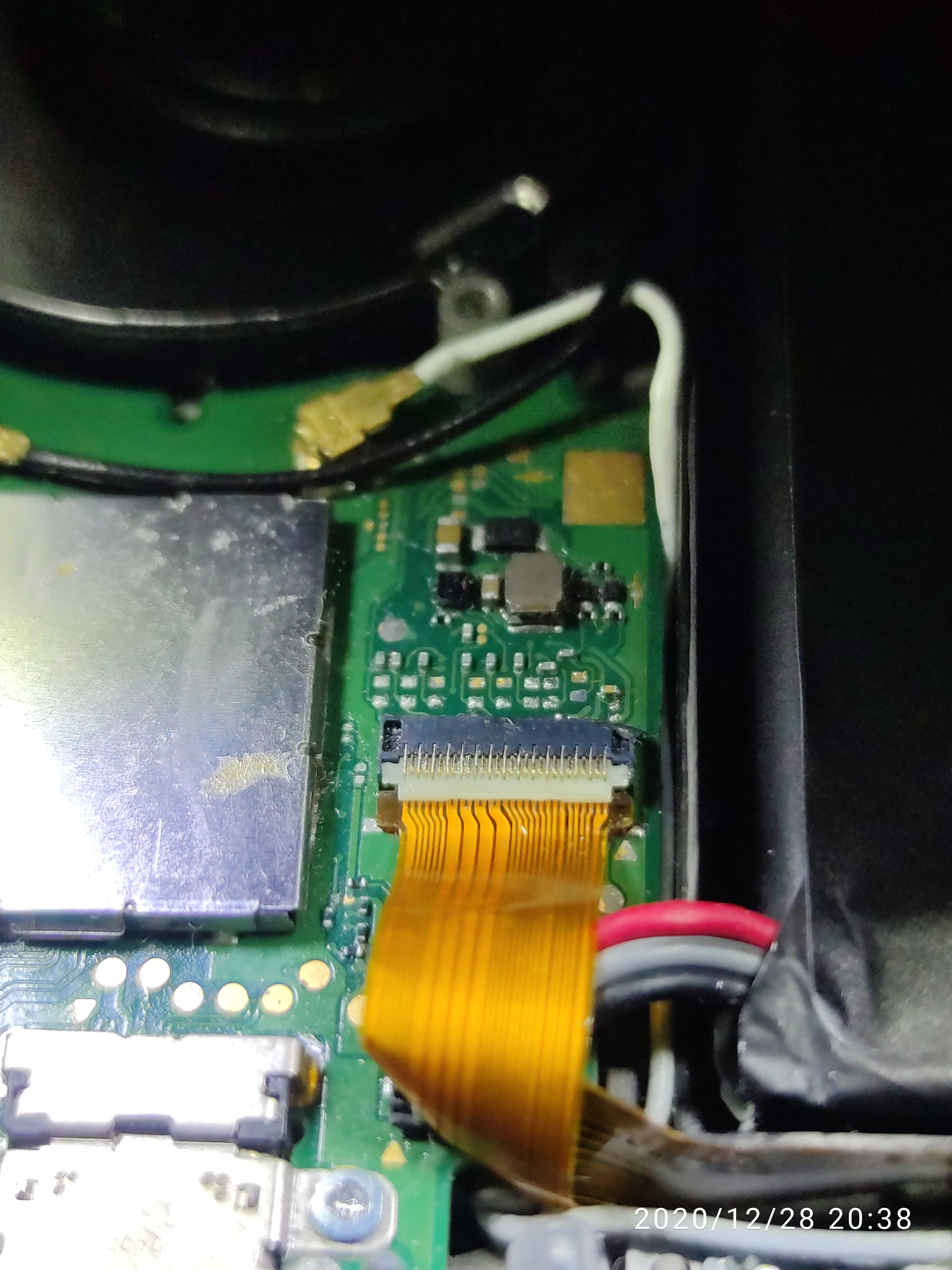
It was a constant 0.41amp before
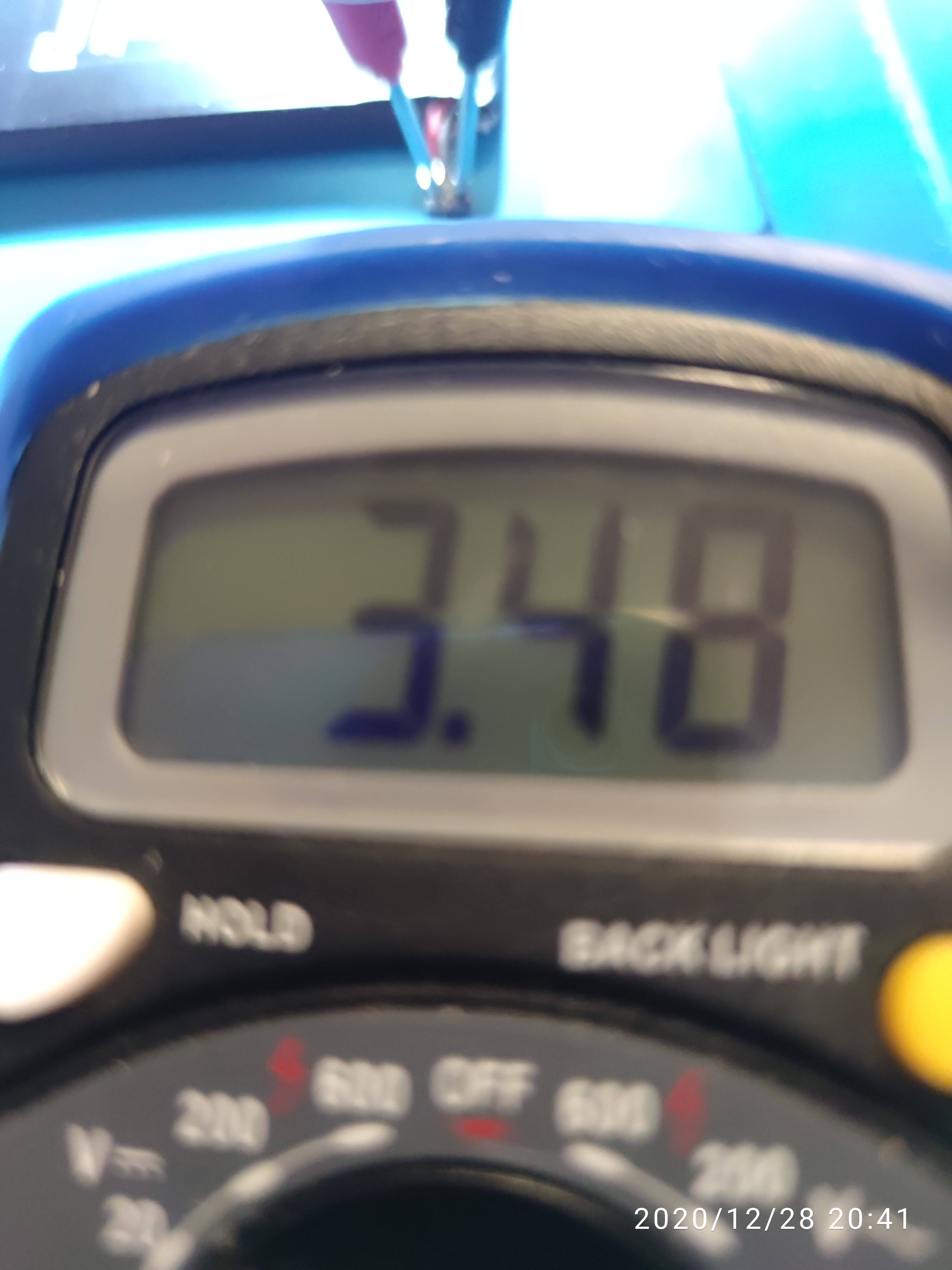
This is the reading from the multimeter.
For the caps underneath the LCD I’m just getting a 1 from continuity.16091882840548284171816199957835|374x500
So the motherboard connector was changed( this one)
It was a constant 0.41amp before
This is the reading from the multimeter.
For the caps underneath the LCD I’m just getting a 1 from continuity.16091882840548284171816199957835|374x500
Great news man, signs of life! ![]()
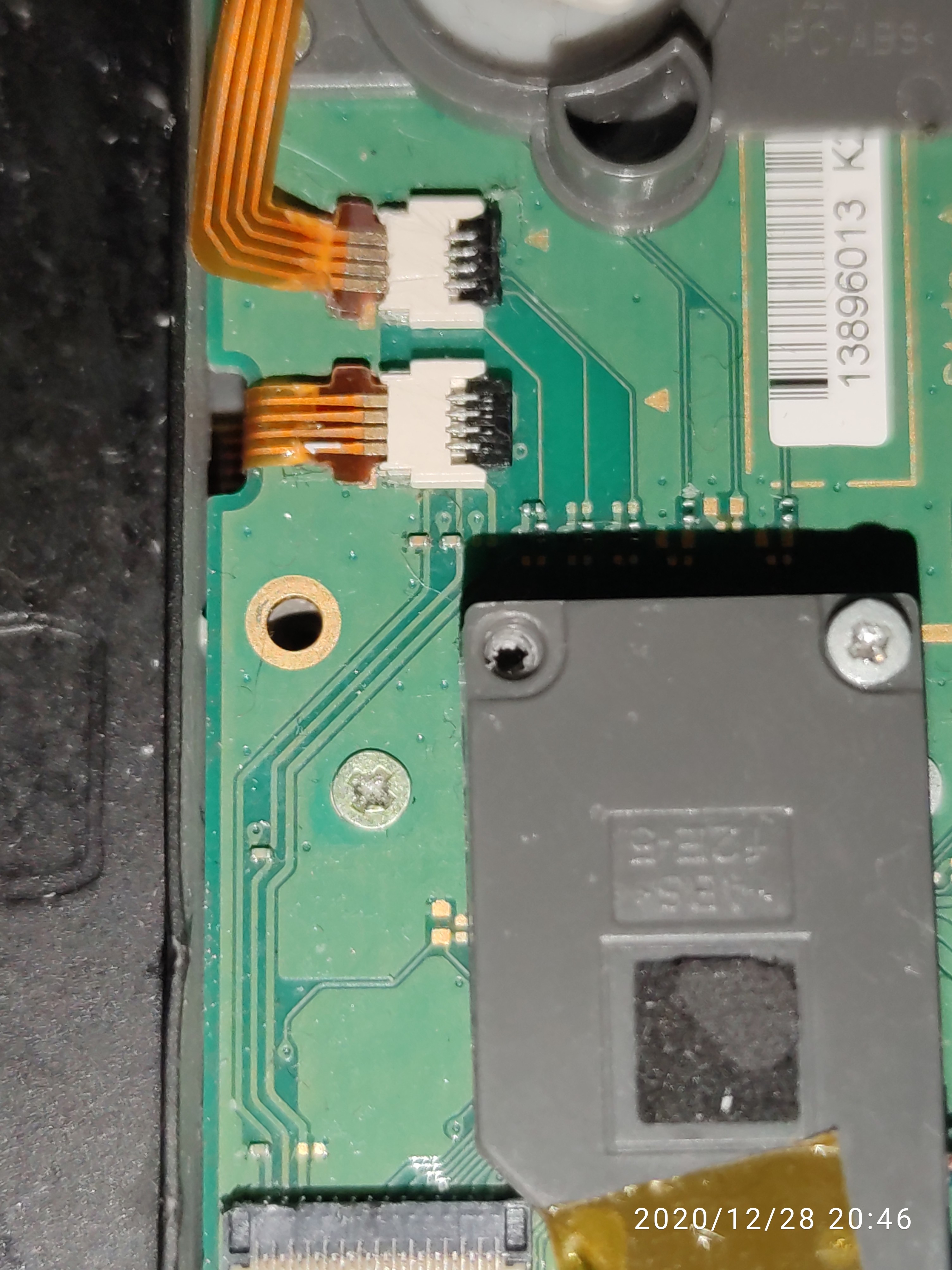
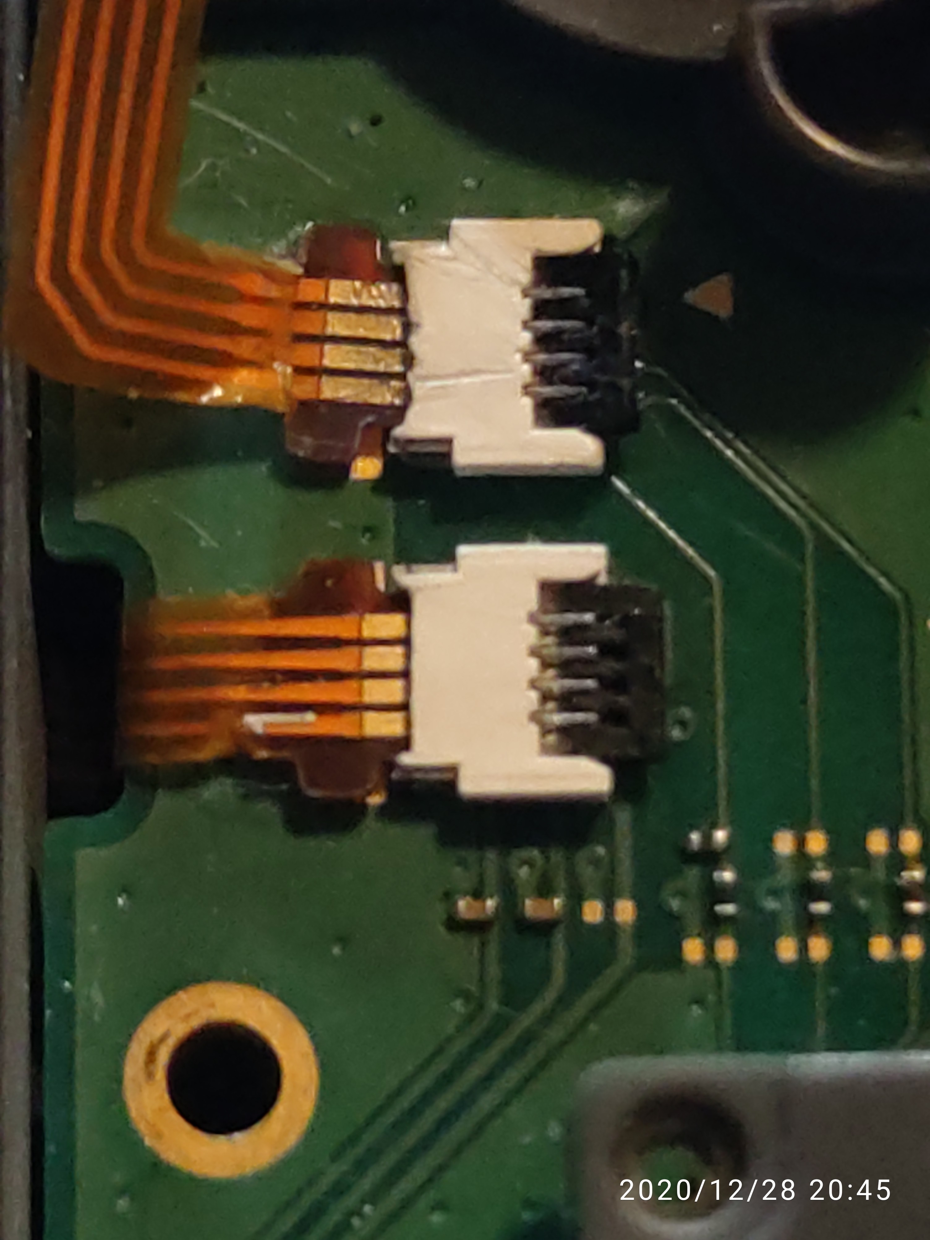
If you can flip the LCD ribbons (and the others) over and take a photo of the contacts i can verify if there’s a potential issue there, sometimes on liquid damaged boards the traces will erode away on the ribbon itself and can often times be fixed with a fine jumper, it’s unlikely the LCD would be bad itself without impact damage or cracks etc as you said it was working prior so i doubt it,…but the connectors on the mainboard are a different story.
Should be fine, will be less than 40C when booted on main homescreen without a heatsink etc which is perectly safe
Unfortunately this image has cropped half of the connector off preventing me from seeing
Don’t take this the wrong way but a lot of these connectors are in really bad condition… even the one you’ve replaced and makes me wonder if you’ve attempted to to directly solder them? or hot air from above? worth noting, a charred/burnt connector will cause high restance accross contacts sometimes leading to the intermittent faults your describing.
I take it you’ve tried applying downward pressure on the connectors and/or flexing ribbons while plugged in to see if you can cause or resolve the intermittent issues (fast charge, lcd etc) ?
Yeah I’ve noticed that too actually, I bought this off eBay actually and didn’t know it was opened before (rookie mistake) the motherboard connector that I have replaced I used very low heat and low melt solder paste to connect it onto the board, the charred side was from me soldering on the last 2 pins as they have not been connected on the board properly, yeah I turned the switch on again and it looks like it’s working fine unless I think I opened up a game by accident, I shall flip all the cables tommorow and take pictures for you! 
Righto ![]()
btw, i would discourage the use of low melt solder for this application and would only recommended using such alloys for solder removal (wicking)
Low melt solders are typically made of a pretty nasty alloys that can eat away at traces over time and also does not have the same current handling capabilities as traditional alloys (63/37 60/40 etc) and also lacks the strength.
I’d reccommend, removing the connector. wicking the pads and tinning with normal leaded solder and for good measure flux and tin the new connectors pins (ball of solder on irons tip - not touching the pins directly with the iron just the solder blob) afterwhich - flux and align the connector and heat the board from below at low to medium air with hot air and let the connector float in place, doing it this way will prevent it from melting or charring.
Also, this is hard for me to check without a donor and i could be wrong but it seems as though you might be missing several passive components around this connector which is a concern…
Hi there,
I unfortunately don’t have any leaded solder only unleaded so would that work or that’s too much heat?
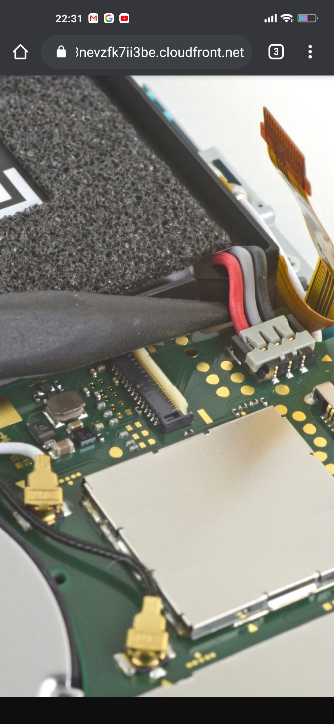
Heres a pic of one that I got off the internet from ifixit I don’t believe there’s anything missing but I shall check tommorow
I’d recommend waiting til you’ve got some leaded solder, try to avoid the temptation of buying it from ebay or amazon where it’s almost guaranteed to be non-leaded despite what the item description/label says and instead order it from a reputable distributor such as Mouser, TME, Digikey, Element14 etc my recommendation would be 63/37 chip quick solder wire.
I’d highly, highly recommend first that you practice removing, tinning and re-soldering a connector on a scap board with hot air… doesn’t matter what, could be an old phone PCB or an old scrap laptop/macbook etc only mention this as i can see from your photo (and i mean no offense here) that you appear to have had real difficulty in replacing that connector as evident by all the excess solder elswhere in the vicinity and also the now missing components.
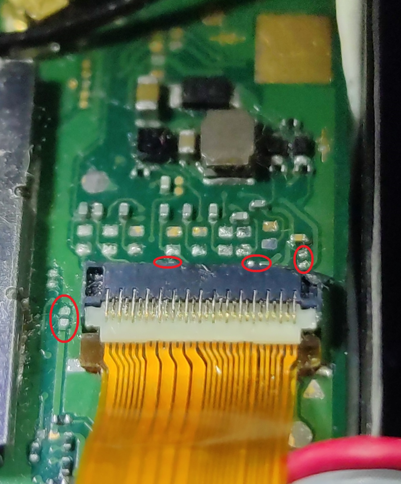
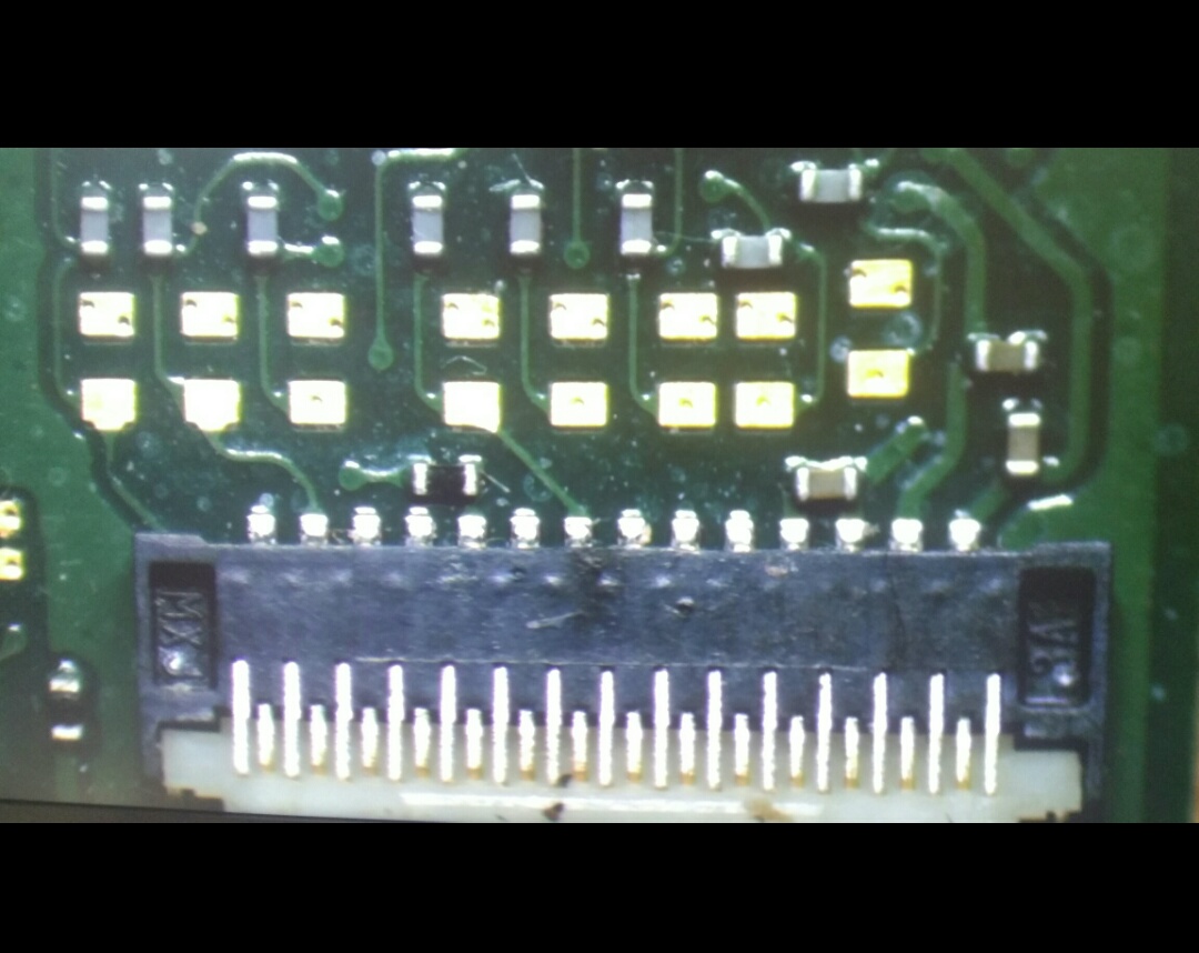
I’ve highlighted all the missing components i can see and also the potentially other missing components, though there may be more as it’s hard to tell based on the angle of your image.
I suppose the next question might be whats the value of these missing components, particularly the resistors… In order for me to help with that I’d need a photo showing where those traces are going and/or continuity to where it’s going so i can find the equivalent component on a regular switch board and provide the value/s
The resistor in the middle is 150/147 Ohms, the one in left corner is 10kOhms
i think the caps are bypass capacitors
Thanks, do you know where I can buy these resistors?
if you have any phone board junk that will do
Can you elaborate more on that? If I got it correctly, you simply soldered down another interconnect cable connector onto the main board and that fixed it for you? I’m sorry, but that doesn’t add up. Its function is to connect the daughterboard, which has the d-pad, shoulder buttons, POW/VOL+/VOL- and send them to the main board. That is it. It has nothing to do with video signal, video feeding or anything else video display-related.
Are you sure you didn’t do anything else after you were done soldering that might have fixed the screen display issue for you? Did you hold down the POW button for 12 seconds, then attempted to power on your Switch Lite by plugging the battery in to the wall?
He’s referring to the daughterboard which is passed backlight voltage etc,While it doesn’t receive video signals directly here it does receive enable signals which will affect the LCD
Coupled with the passthrough connector issues and now missing components, this represents the issue in relation to observed fault.
Would guess the scorched connector was only barely doing it’s job to begin with but then it was disturbed during joystick replacement
Do you think he could have concluded the interconnect flex cable was at fault if he tried checking for continuity from one end of the cable to the other one?
On Friday, another customer brought her Switch Lite in, which was purchased from Ebay. Previous owner, according to her, had attempted to mod their Switch Lite, with no success. She came to me, I removed the modchip, but in the process I ended up losing this cap.
No, while a break on the cable represents it’s own set of possible issues it alone wouldn’t rule out a fault. For example, if the ribbon cable is good and has continuity end to end but the corresponding connector is scorched, then expect issues, scorching will cause high/low resistance across pins and even if it does work, leaving it or ignoring it presents potentially more serious issues in the future.
If one side of the caps pads = ground then in all likelihood the cap was bypass.
Check the corresponding rails the modchip was connected too (caps) in resistance and see what they measure
So does that mean if something is wrong either with the flex cable or the connector (from the main board or the daughterboard), because the daughterboard has the backlight connector and the daughterboard isn’t functioning properly, that will prevent the screen from displaying anything, EVEN THOUGH the backllight seems to be working properly?
Well technically any major fault on the daughterboard could have a negative impact on the mainboard, there are several critical rails there after all.
This would be where the current meter comes into play… though, will say I’m not as familiar with Lites and don’t know bare minimum required for normal current readings
Yeah, that’s likely your problem