Hello there, I’m trying to fix this switch lite I had to open up to change both joysticks, when I put it back together I saw that it is charging only on 0.41amps and when it’s on charge it turns on only the backlight, can I get any suggestions on what I should do? Thank you.
Similar problem here, actually registered just to try and find some info. I actually have a brand new digitizer and screen, the device works (sound, controls, touch all work) and the backlight is definitely on… but no display. This is a previously completely functional, brand new Switch Lite that was working fine before re-shelling it, but I can’t see any damage anywhere on the boards, flex cables, connectors or anything. I’ve used 99% iso to clean every contact and all the flex cable connections…
Everything I see about black screen issues on the Lite seems to be either contacts need cleaned, damaged flex cables or the screen works and the backlight doesn’t. I have the exact opposite issue and it’s turning into a really frustrating and expensive project.
I don’t have any lite donor boards handy but from memory theres an enable present on both the backlight ribbon/connector and LCD/connector
Verify continuity where possible on all end to end ribbons at the base of connectors joint (power/battery removed)
Check inductors aren’t open and trace integrity
check backlight voltage.
How can I do those types of checks? What am I looking for exactly? Shortages and low voltages or spiked voltage with fluctuating readings? Thanks again
Hi again,
In your case, can you confirm you’ve changed the mangled connectors to new ones?
Unfortunately i don’t have any switch lite board atm to do any sort of diode or resistance measurments to ground on the connectors for you in order to compare values, i do have a mariko board though which component wise is near identical…
If you have a donor or known good lite board then take those measurments on the LCD connector etc and log the results and compare to your bad board, if you find a pin that isn’t measuring the same or similar then post the result.
To check for continuity, just put your meter in continuity mode and check you have it from the LCD ribbon pads to the relevant base solder joints on the back of connector (beep) or relevant surrounding component,
If you don’t have any points to measure from on the LCD ribbon (because it’s blind or reversed) then i’ll typically use a ribbon cut from a cracked LCD and use that (flip if neccessary).
Checking for enable lines is a bit more difficult as lites use a different connector so again, can’t really tell you where to measure.
but you can check, on the original switch board it uses an IC 8316 (BD8316GWL) to generate a positive 5V and negative -5V i believe for the contrast on LCD, it’s by the LCD connector on original switch but you should have one somewhere on lite or an equivelent, afaik if you weren’t getting this then the LCD wouldn’t come on, you can check for the voltage on two of the larger caps surrounding this component, if you aren’t getting these voltages on them, then you could check that this IC is getting the enable signal (from the soc i think) on the relevant points indicated in the datasheet, i believe they should measure 1.8V., if in your case you measure 0V here it means the IC is not even being told to turn on
To check which pins are your main voltage rail on the LCD ribbon without a donor you can disconnect LCD ribbon, take a close look at it and see which are the larger traces, then see which is the corresponding pin on the connector, the thicker traces on the ribbon (will be two pins visibly joined typically) will either be ground or your primary voltage, once youve identified which pin they go to on the connector, check which of them are ground in continuity with your meter and rule them out, now put battery/power back on the board and measure the voltage on the pin you identified and report back the voltage measured.
Finding enable/s without a donor on the connector itself is tricker but possible and requires an even lengthier explanation, once you can confirm the connector has been swapped i’ll go into more detail if you would like.
In the case of testing the inductors, i beleive there is a gang of them surrounding backlight cable connector on lites, check they have continuity (beep) and check trace integrity up to the connector, though it doesn’t seem the backlight is your issue as you seem to be getting light, though i can’t rule out the possibility there is also an enable on the this connector which would prevent LCD from coming on if not present.
One thing i forgot to mention which is a nice quick test,
If you disconnect the backlight ribbon, digitizer ribbon, and LCD ribbon and plug in the battery, and then connecting USB does the current jump from 0.4A to high current? (assuming the battery isn’t fully charged, it won’t jump high if battery is charged 95% +)
If it does then that would verify my suspicions and further point to a bad connector (or something else affecting it) disconnect battery and reconnect one ribbon at a time, plug the battery back in and if after plugging in a certain ribbon the current doesn’t jump from 0.4A to high current then you’ve identified the problem connector/ribbon.
I took out all the ribbons and the charging jumped up to 0.33amps, I’m gonna try out some further tests, any more suggestions I will welcome them!
LCD when plugged in gives out 0.36amps
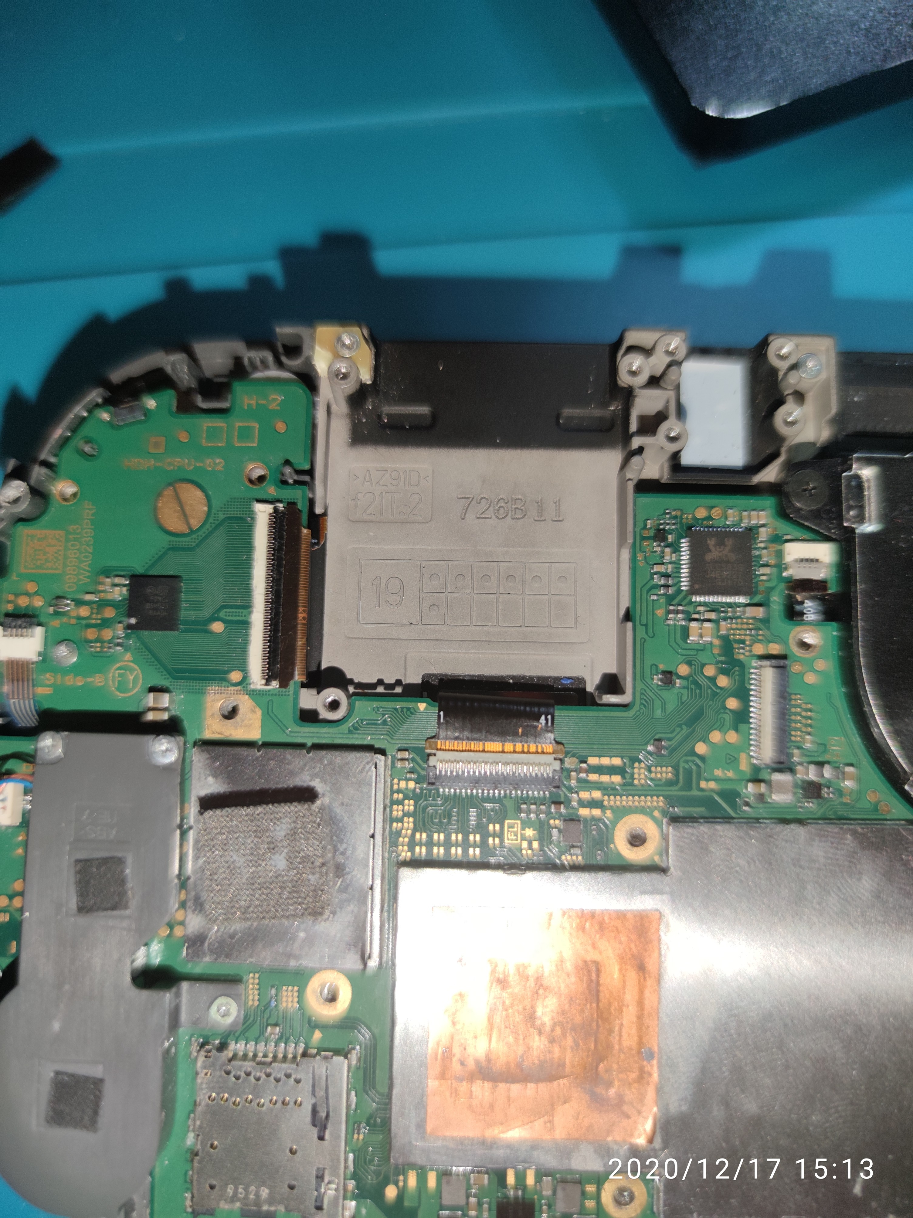
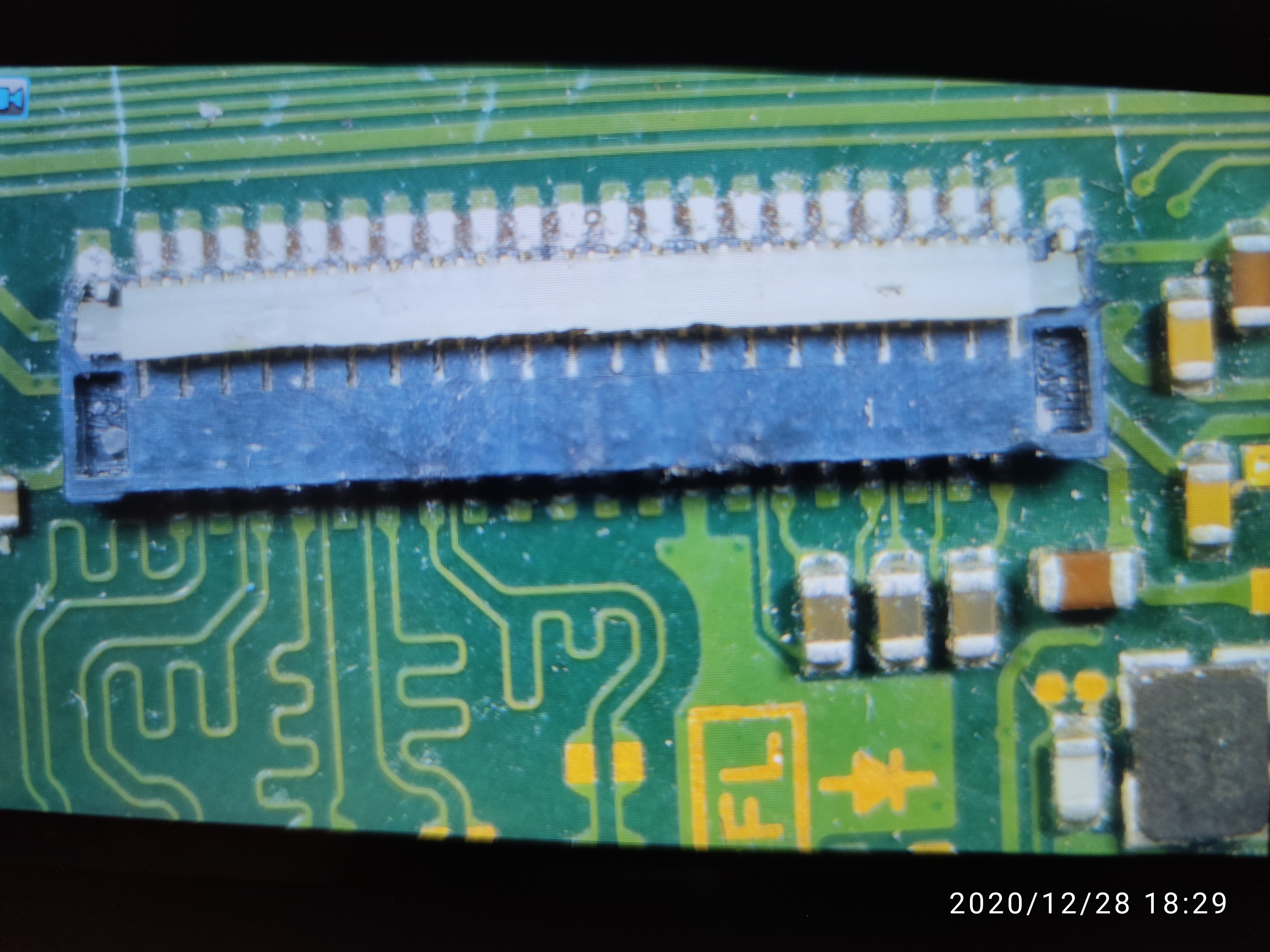
Continued from above I took out all of them and replaced each and every one individually, just a quick question though do you know which one is the digitiser and which one is the LCD on here?
Unfortunately I don’t have any donor boards available to check for LCD measurements but I can carry on measuring tommorow as I’m am very busy today and only had about an hour to check sorry.
Could be wrong but i believe the center one is LCD (with 1 to 41) i believe mymatevince youtube channel has done some beginner switch lite repars where you could confirm and follow along possibly?
The backlight connector is the smaller one i think and i think the digitizer is the largest one (looks the to be the same connector as regular switch)
Just to confirm, does it drop to 0A before going to 0.33A?
Also if you were getting 0.4A before and you are now getting approx or < 0.3XV it would imply the battery is fully charged. If it is, connect the battery to the switch and without the usb and turn it on and let the battery discharge a little over night and repeat the tests with all ribbons removed.
You could also just measure the battery voltage to give a rough indication of charge %
Also, hopefully goes without saying but dont disconnect or reconnect any of the ribbon cables while the battery or USB are plugged in
Hi thank you for the suggestions, I just wanted to tell you the switch does not turn on when I don’t plug it in but when I do it turns on but when I instantly take out the charger the switch turns off.
Hi, yeah when i say turn on i mean behind the scenes… the switch will draw anywhere from 0.2 to 0.4A from the battery in it’s current braindead state (after pressing power button and with no USB connected).
I’m asking you to do this to discharge the battery as a current reading of 0.33/0.36A with USB power connected indicates the battery is fully charged, until the battery is discharged you will not be able to see the switch switchover to fast charge (high current) and as a result you won’t be able to peform the previously mentioned simple test as the results will be invalid…
If you have any resistors handy i can tell you how to discharge the battery without using the switch board, but my assumption was you wouldn’t have any?
No unfortunately I do not have any, I got them ordered though but is there any other way I can check the voltage on the battery using my multimeter? Maybe see how much it’s full with a reading?
And also another way for the battery to be discharged?
you can measure the voltage on the battery with your meter in dc voltage mode.
Likely you won’t be able to fit your probes inside the connector terminals directly , in which case plug the battery into the board and measure from the much more easily accessible corresponding battery connector points on the board, red on corresponding + and black on corresponding -
not unless you can pull a through hole resistor/s off something else
Hi again,
Sorry for the late reply I’ve replaced the mangled motherboard connector and I’m getting a backlight with 0.41amps being drawn again, and I tested the battery which has 3.2 watts I believe? So I think the battery is still charging, I still have not checked the LCD connector for any shorts or continuity but any other suggestions will be appreciated.
Also those three caps at the bottom of the LCD connector are not responding at all I can’t get a reading off them no matter how hard I try.
Hi,
Can you let me know specifically which connectors have been changed?
Can you confirm for me, when plugging in the USB is the current going from 0.41A to 0.00A and then finally back to 0.41A ? or is it just a constant 0.41A ?
Where are you getting this reading from? 3.2V maybe ? or is it the watt reading on usb ameter ?
What sort of reading? I don’t know what those capacitors are off the top of my head tbh but presume they’re bypass caps, if you disconnect the battery and put your meter in continuity mode and one probe on ground and the other on one side of the caps your meter will likely beep one way indicating they are indeed bypass. you might then try plugging the battery back in and prompt to boot with cable then measuring the voltage on the non ground side of these caps.
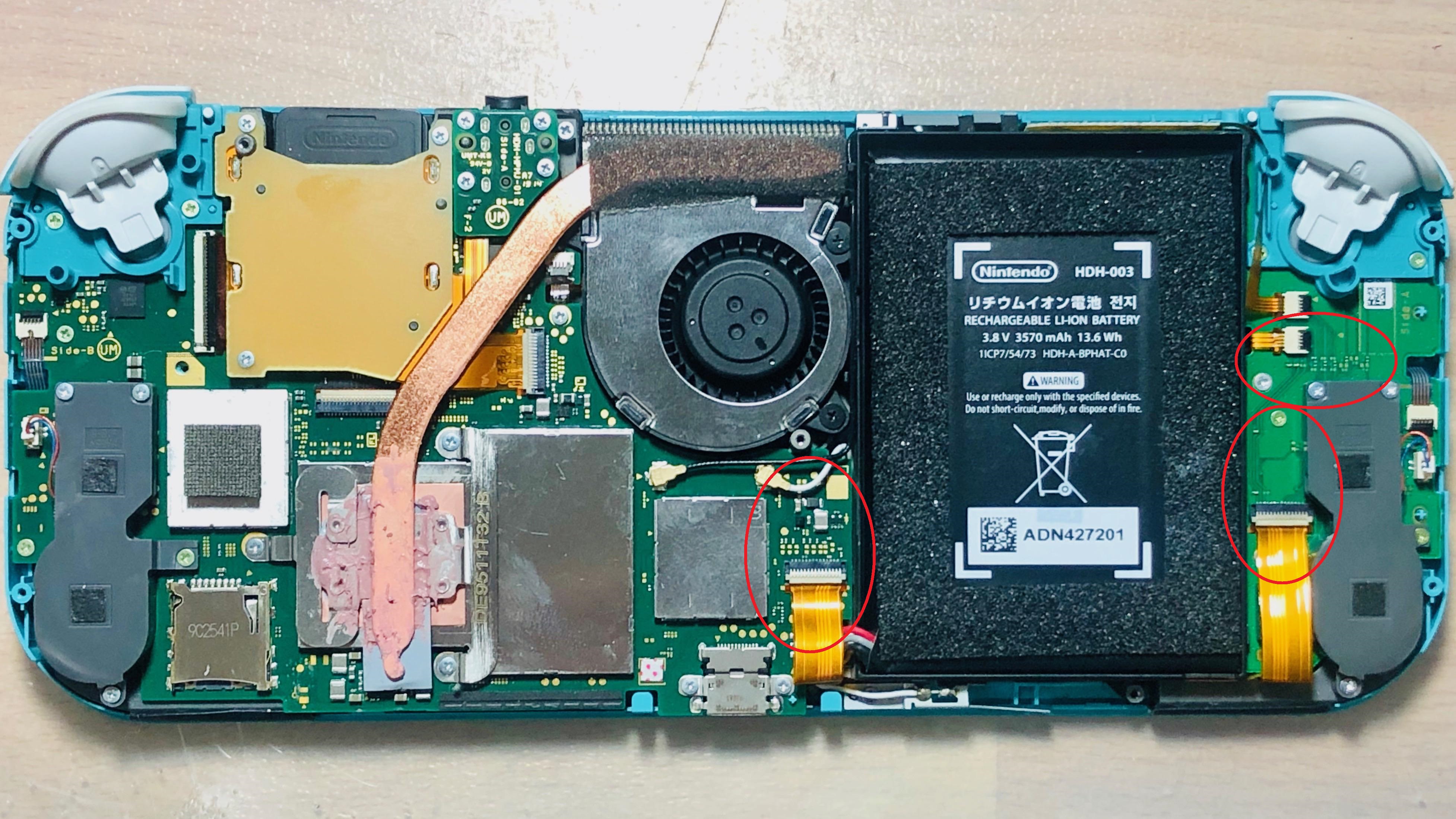
Can you take a clear photo of the backlight connector/s a bit more zoomed out so i might inspect surrounding components and also of the “passthrough” backlight (etc) connector and surrounding area… given the initial fault was caused after a analog stick replacement i have a high suspicion of these connectors in the area…
A photo of the originally scorched connector would be good too.
I’ve highlighted them for you
Hi there, I’ve actually got some amazing progress right now I put everything back together after cleaning all the ribbon cables with a glass fibre pen and I put it back to where I can turn it on again, I’ve turned it back on and saw that it jumped from 0.41amps to 1.09amps and the switch started up I heard sound and also moved it around like normal but there was still no show on the LCD, I’m going to order a new LCD now however as of now the switch gave me the sound of a error and now when I turn it back on again without charging it turns on but after the second flash of backlight it turns off again, I removed the original thermal paste a long time ago, do you think that it’s because the switch is overheating now?
Thanks