Basically what the title says - I have replaced the battery in my son’s Switch Lite, but to no avail. His switch stopped charging prior to me replacing the battery, so I now know it isn’t the battery. I really would love to be able to effectively diagnose and replace whatever part needs replacing. I have the means with which to solder and replace pieces on the PCB if that’s what it comes to. I just don’t know how to diagnose each specific part of charging a Nintendo Switch Lite. There are so many components on the MB and I have no way of knowing which ones to check. I have a multimeter, I have magnifying lenses, etc. Can anyone help me get started? I don’t want to desolder the USB-C port if I don’t have to. I’d rather start with diagnosing first and then replacing as a last resort. Any help is appreciated!
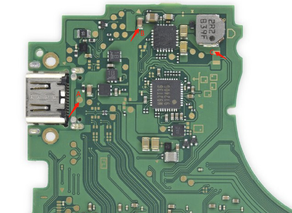
take out the board, flip to the back. plug in official charger.List the voltage you measured from A,B,C point
Thank you for the instruction! Just to clarify, when you say “List the voltage you measured from A,B,C point”, are you saying that I should use a multimeter to measure voltage at point A, and then at point B and then at point C? I’m not checking for continuity between those points or anything, am I?
That’s right, measure the voltage of each point
Ok, thank you for confirming! Will do and report back.
Ok! Results are in:
- Point A measures at 5.24 volts
- Point B measures at 0.04 volts
- Point C measures at 0 volts. I couldn’t get a measurement there.
well since B is 0v which means BQ chip not working, something goes wrong on between charge port and M92T36 charging ic
Gotcha. So was the point at B called the BQ chip? Where can I also find the M92T36 charging ic? How would I troubleshoot this further?
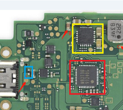
Yellow Box = BQ24193
Red Box = M92T36
BQ is avaialble via digikey, M92 is only available on the secondary market (ali, ebay, repair shops etc).
The part highlighted in blue is a small fuse, make sure this fuse is still good by putting your meter in continuity mode and ensuring you have a beep when you place the leads on either side of the fuse. If this fuse is dead then you won’t be able to charge. If you’re using an OEM charger, the fuse is good, and you’re only seeing 5v show up, then M92 has died on you and needs to be replaced. I am assuming this is the case since you are only measuring 5v at point a which is the TP for VCC in. You can also test the capacitors surrounding both M92 and BQ for shorts. You should have a beep on one side, and not the other, if a cap beeps on both sides either the cap or the chip is faulty. Usually better to pull the cap and test it first before removing the IC. IMO it’s far more common to see M92 die vs BQ.
Do you have, or have access to, a USB-C ammeter? They’re pretty cheap tools and quite handy, it will let us know the charging current you have (if any) and can be further used to diagnose issues here.
Thank you so much for this instruction! I’ve tested the fuse you outlined in blue, and we’re all good there. These components are so small LOL. So, is there a way to definitively tell whether or not it’s the M92 chip or the BQ chip? I’m thinking that I’ll check all the capacitors around each one, but then I would have to dive into microsoldering. Any tips or tricks you would recommend in replacing it? Any tools, etc.? I will definitely look into the USB-C ammeter and get one purchased ASAP as well.
That fuse is a tank, its nicknamed the invincible fuse for a reason, but its always good to rule it out.
Unfortunately there is no definitive way to know if its one or the other without just pulling and replacing. The best you can do is get as much information as possible to make an informed decision on which to focus on. I generally focus on M92 first, its the more fragile of the two and directly interfaces with USB so it often is the first to go. If you’re sure the USB port is not mangled, unplugging the battery and plugging in an ammeter is the first step. On a healthy circuit with OEM charger you would expect to see 15v in and a current draw of .09-.1a (which then drops to 0 as the regulators switch off). Signs of M92 being an issue would be seeing only 5v, or having the meter constantly flash on and off (shorted component). Then you just have to take your multimeter and start testing, test for shorts around the IC’s, grab a diagram of expected voltages on passives surrounding said IC’s (keep battery unplugged during these tests, USB-C only, and approach with kid gloves since slip ups can fry things).
Most of electronics repair is centered around using all the context clues to narrow down the area to focus on. End of the day sometimes you’re just forced to pull things and test again, but hopefully by that point you’re fairly confident of the issue.
Just keep in mind that when it comes to board level repair, you may be forced into purchasing some equipment to get the job done. If you don’t have a hot air station, you won’t be able to replace M92 or BQ and will find it difficult (if not impossible) to replace 0201 sized passives and the like. So weigh that in when it comes down to deciding to send it in for repair, or if you want to DIY, end of the day you are going to be paying out of pocket for something. Just the nature of the hobby.
Awesome. Thank you! I was a little hesitant in signing up for this forum because I was worried people would be annoyed with my noob questions. You have been so helpful and made me feel more at ease. I appreciate it!
I do have a hot air gun, but its surface area is large, much larger than that specific point on the board. Is that what you mean by a hot air station? I imagine there’s a tool which is smaller (in terms of hot air distribution).
What other equipment would you recommend I purchase if I’m going to get into this as a hobby? I really would like to get into this!
No such thing as a stupid question, we all started out knowing nothing too, everything just takes time, practice, and money.
Hot air guns aren’t really suitable for this type of work, they might work on certain jobs, but definitely not for micro soldering.
https://www.amazon.com/gp/product/B08BK3M6YW/
something like this yihua is what you’re after. Variable temp with swappable nozzles.
To get started in repair you really just need 4 tools:
Soldering station (T12 style recommended)
Hot air station
Multimeter
Magnification (either microscope or digital microscope but very high powered magnifier lenses could work as well)
of course you will need some supplemental stuff such as flux, solder braid / pump, tweezers, work mat. On the whole though you can probably execute the majority of all repairs with that workbench kit. You could probably put together capable equipment for around 400-500$ with all of it being sourceable on ebay / amz / digikey.
As you’re just starting out, id look into buying completely junk boards or practice kits to learn on. Some of the practice kits are fun to work on and give you a working toy in the end. End of the day its best to learn on something that isn’t the project you’re working on, then once you get comfortable with the work move on to the actual project. Better to mess up on junk then completely ruin what you’re trying to fix.
Sorry for the late reply here, but I mega-appreciate the recommendations. I won’t be able to afford this equipment until next month, but that’s fine with me. The kid can live without his switch until then ![]()
Once I get the equipment, I’ll update this thread with my results, etc. Would you have any other insight/advice for me?
Thanks again, this is super helpful and will help me get started!
Hi Bud, I have kind of same problem, so there is 15V on point A. Fuse is good and its 15V from boths sides. Point B is 15V as well but point C is showing only 0.27V? Should that be 15V as well? And if so what should I change? Thanks
NO, points C shares voltage when battery connected, It should be 4.35v max. Check if you battery is 0v
So when battery connected its showing 3.5V. Console will turn on but it won’t charge. Tried with new M92 and BQ and Max IC. It geting 15V and pulling 0.70-0.80 but its not going over that.
15v 0.8amp but not charging? how come
Its showing charging but percentage is not going over 1% while on charger. I boosted battery with 4.3V and lift on 10% just to make sure its not battery problem, but when console is on and on charge it will come eventually to 1% and switch off.
It seems like the tiny fuel gauge ic max17050 isn’t working propperly. If this ic fails, the actual voltage of the battery doesn’t match the percent of battery fuel gauge anymore. I would check the max17050 and surounding components.