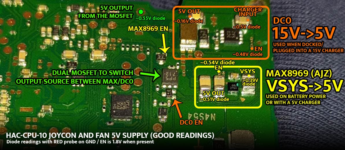
It ended up being an issue with damaged pads under the CPU. As it turns out, 15V → 5V conversion is done by the chip marked DC0 and VSYS → 5V by MAX8969. Due to a lack of proper connection with the SOC, the EN signal for DC0 IC wasn’t present which was the cause of my problems with this switch.
In the picture below I marked good readings for this area along with my findings about this circuit. Check whether you have an EN signal for DC0 (should be 1.8V when present). You can also check the EN point in diode mode and if you have a connection issue like I did it will measure around 0.7V.
One important thing is that 5V output will come up only when the switch is fully booted up and you connect up a joycon or the fan is spinning - which makes it hard to measure this area for voltages.
So in conclusion the problem is not resolved, or it is difficult to be resolved, as it has to do with CPU connections?
I did measure the EN pad as per your instructions, 0.58V in diode mode, switch booted from battery and 15v charger no EN signal. Though didn’t have 1.8v even with 5V charger, though i didn’t have any peripherals connected.
The best way to measure voltages in this area is to hook up a joycon rail with a joycon that wants to charge - this way you will be sure that either DC0 or MAX8969 should be outputting something.
I did manage to resolve the issue on my board but due to other issues related to BGA rework this board ended up as a donor for now.
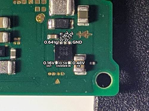
Here are the diode readings of the DC0 chip. If you have a burn mark near the chip I would remove it from the board and check the pads for damage.
Something similar happens to me but the opposite, when I connect the 15v the fan works at maximum, it does not stop and the joycon charges, when I disconnect or put a cable to 5v the fan stops working and charging the joycon, I have changed ajz, Pu and already crazy and it remains the same, it is one of the plates that does not have the protection diode, I do not know if the bq has it is there something to do with it?
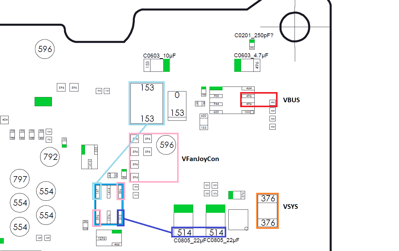
I would check the shown ciruits. The pink is the power rail for Fan and Joycons. The blue marked mosfet is the input switch between Vsys by battery (dark blue) and Vbus by USB C source (light blue).
Almost all the measurements are approximately correct, except for the light blue at the MOSFET output, which gives me 108, and when it reaches the coil and all that area, the values of 153 give me all 108.
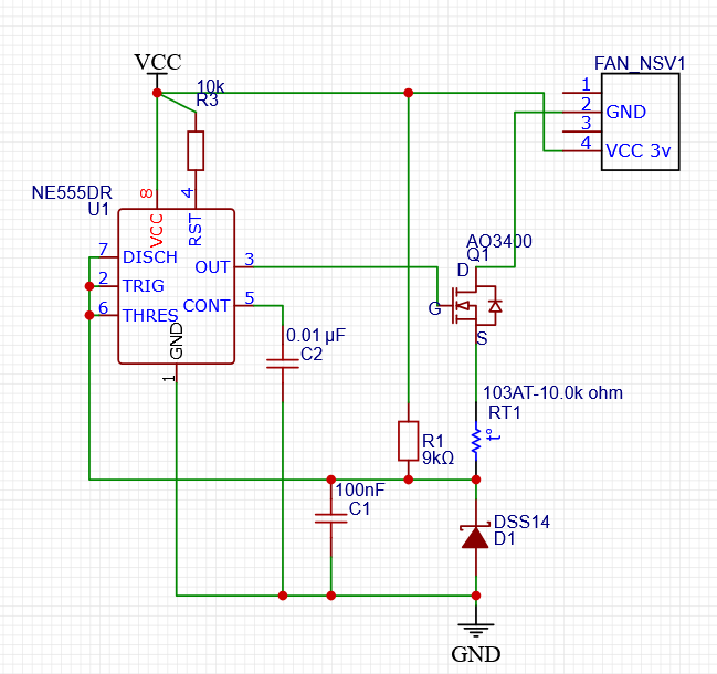
I changed the components of the lines and nothing solved the problem of charging the joycons and FAN, so I started to create a circuit to control the fan, as for the joycons I will use an external charging doc, when I test everything I will post the results.