Hi! I have a Switch v1 with a weird issue where the fan doesn’t work and joycons don’t charge when the console is docked or connected to a 15v charger (Official Nintendo charger). I also tested this with a 5v phone charger and the issue didn’t appear. There are no shorts on the fan connector itself. What should I check? Thanks.
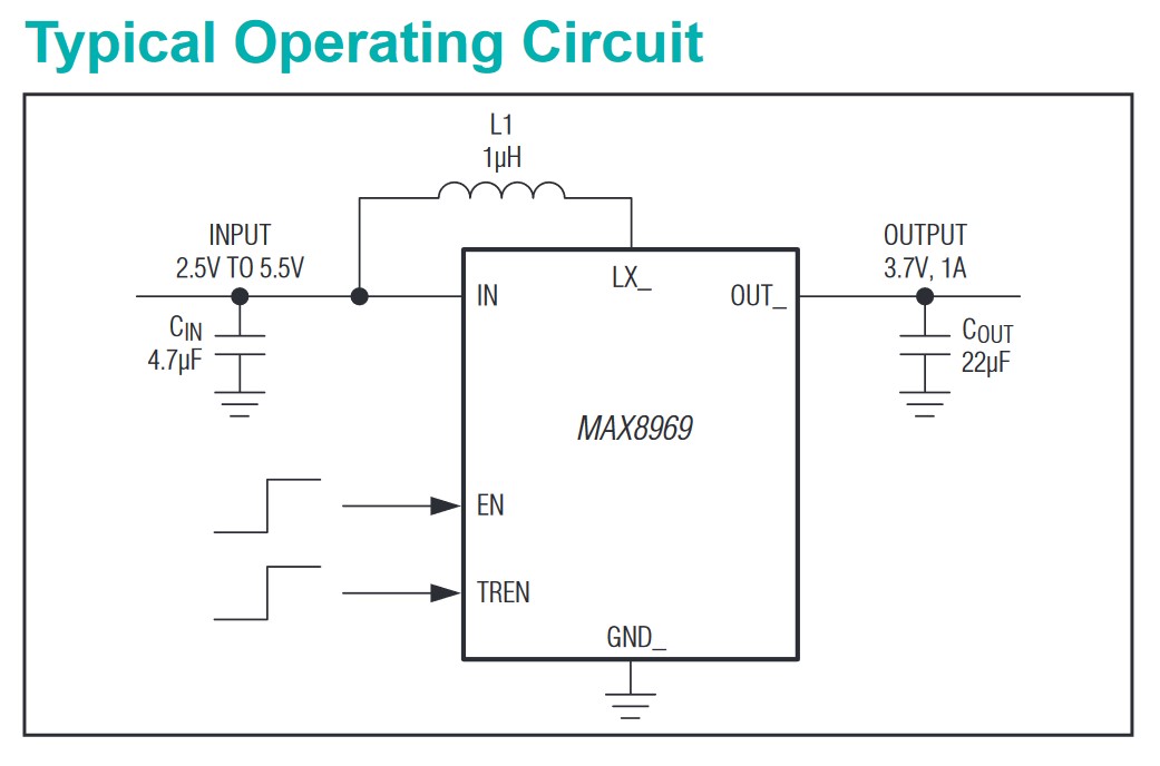
There is a MAX8969 that provides 5 volts to the fan and joycons. It’s a small 3x3 BGA and it will likely be smoking hot when plugged in. Should be labelled ALJ. I just had this exact same problem on an OLED but I also had to replace the fan, joy con voltage regulators and the small 2.8k resistor next to the 8969.
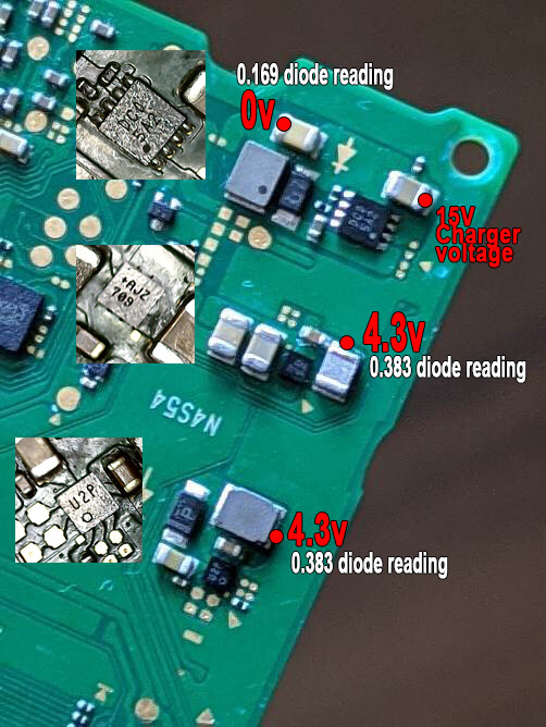
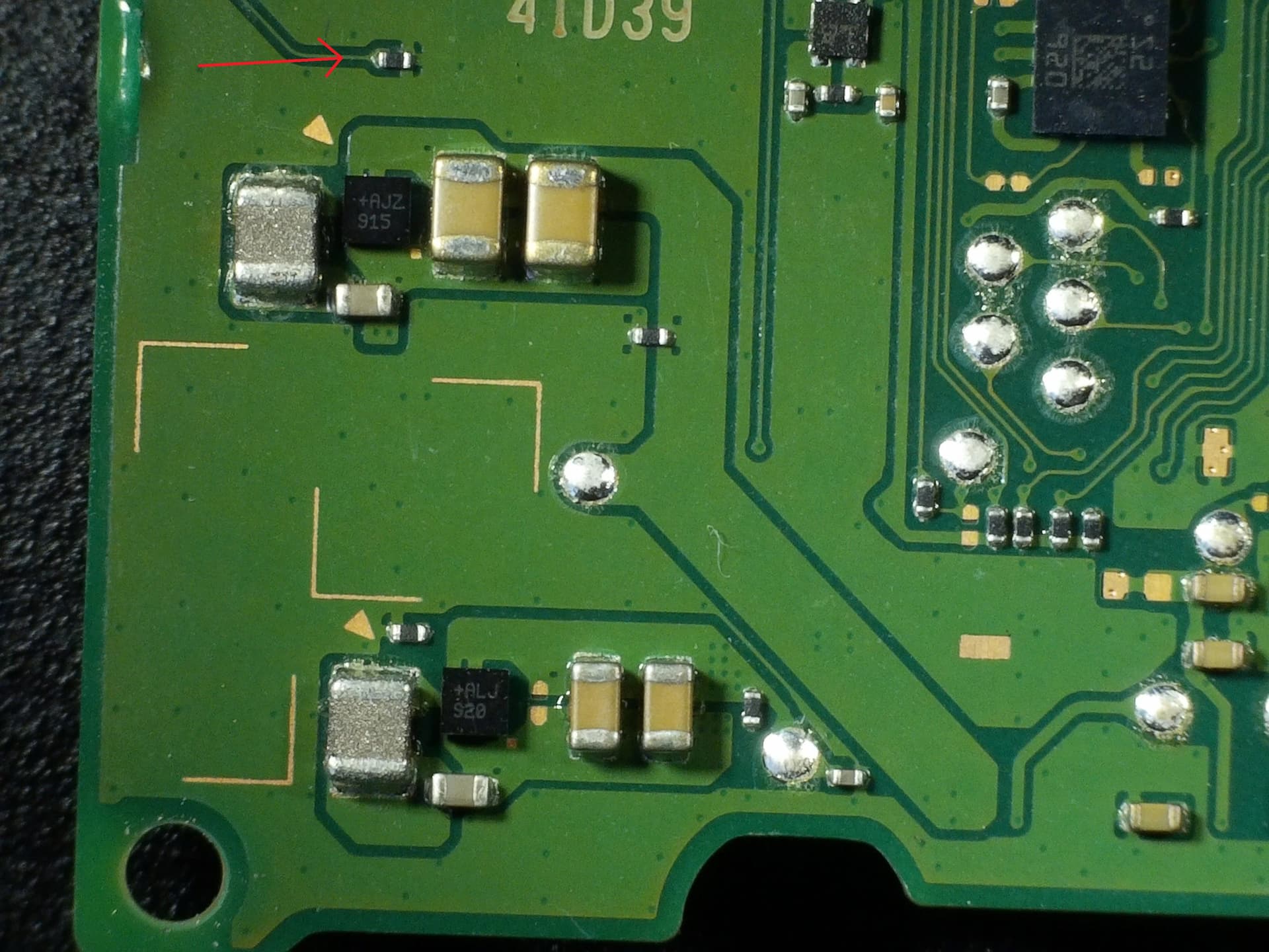
Closest marking I have to ALJ is AJZ (might be the same chip with a different date code). Could you confirm I’m looking in the right area? Nothing seems to be heating up there. I also made some measurements and diode reading on the top chip seems a bit low though it might be normal as I don’t have any board to compare it to. I made these measurements by plugging in just the board outside of the housing. I also soldered wires to these points and measured voltages when the console was running and the voltage on that top chip is still not present when console is turned on.
do you have a small diode located right behind the FPC connector for the fan on your board? This part has been known to cause no fan / no joycon problems and can be safely removed as it was deemed unnecessary on later revisions.
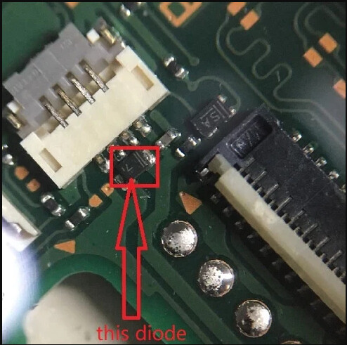
My board revision doesn’t have this diode near the fan connector.
A small update to my previous findings: these diode readings seem to be good after comparing them to ones I found on the internet. I think it must be something to do with that top chip not producing any voltage (DC0 marking).
Did you check the charge port fuse? AJZ is the 5V version of the MAX8969. ALJ is the 5.3V version. I think the DC0 mosfet is related to the display connector.
I have been poking around a V1 board I’m working on and this circuit is a bit different than the switch v2/light/oled. On the V1 the 8969 generates the 5V rail and it goes to a mosfet labelled PP5 close to the chip. From the mosfet it is distributed to voltage regulators for the joycon rails and fan I presume(I haven’t traced the whole thing). On the other switch versions there’s no mosftet. It goes directly from the 8969 to voltage regulators for each device. I still think your 8969 is toast but it could be that mosfet.
To test, power the motherboard and check the two caps next to the chip. One side is ground and the other should show 5V. That’s the output voltage. Check for the 15V input as well. It should come off the smaller cap going into the inductor. Google up the datasheet for the chip, it’ll help.
I checked the charge port fuse and it’s good.
There is only a few mV or so on that output caps near MAX8969 - which is not good. On the small cap I get 4.3V when connecting a 15V charger. Although maximum input for MAX8969 according to the datasheet is 5.5V (picture below).
I only get the desired 5V output on these two caps when the console is fully turned on and I connect up a 5V charger instead of a 15V one - which would explain the weird behavior with the fan and joycon charging. On the 5V charger input for the chip stays at 3.8v so a bit lower than on a 15V one. Should I change it? I don’t have any donors at hand so I’ll have to buy it.
I dived in further into the datasheet and I checked the EN pin which goes to a few of the unpopulated pads near the small cap. When I connect up a 5V charger there’s 1.8v on EN and so the chip outputs 5V, but with a 15V charger I don’t get any voltage on EN.
This still can be this chip that’s pulling EN to GND when it’s supplied with higher voltage but it would be good to rule out the possibility that something might not be telling it to turn on before I buy this chip and replace it.
By looking at the PCB scans from the internet I figured out that it goes to the component near the PP5 mosfet you mentioned. It’s marked with 42. But it also goes to the CPU so I hope there’s nothing wrong there.
If you have an m92 on hand try changing that first. It could be mishandling 15v charging. Considering the 8969 outputs 5v with the 5v charger it’s likely fine. You could try removing it and seeing if the enable pin gets 1.8v with the 15v charger.
I have the same problem, but I have version 2, can anyone tell me where to check the EN signal without removing IC
I replaced M92 and sadly it didn’t resolve the issue. So I pulled 8969 and even without it EN is not present when connecting a 15V charger. So I think we need to track down what actually sends that EN signal.
As for checking EN signal on a v2 board (@zjozjik), I didn’t find any PCB scans for v2 switch and from pictures I found online of this area it looks like there aren’t any pads nearby with EN signal like on my board.
I’m confused. Since my switch is moddable I booted up Linux and fan works there without any issues on a 15v charger. There’s no joycon charging, but they won’t charge with a 5v charger too so I guess it’s expected. There could be two explanations for this: Linux handles fan control differently than stock firmware or my firmware is corrupted.
I rebuild my system image from scratch and the fault didn’t go away, so Linux handles fan control differently. I can probably force the fan to work with some homebrew app and use 5V charger to charge the joycons - but it would be nice to figure this one out.
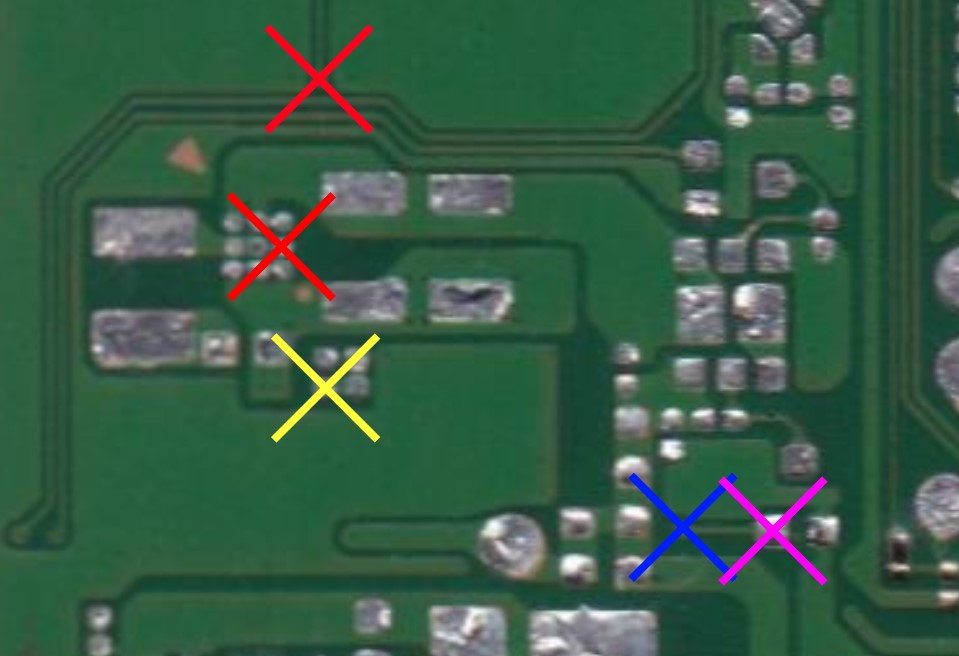
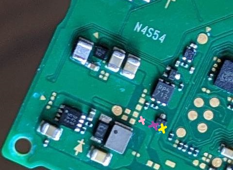
Definitely very strange. I wonder if there’s some check that stock firmware performs before enabling that rail that linux doesn’t do. I followed the EN trace to the CPU but it also goes in the other direction. Do you pick it up on the purple, yellow and blue mark in my picture? Can you tell what component links purple and yellow? I don’t have one on hand to check.
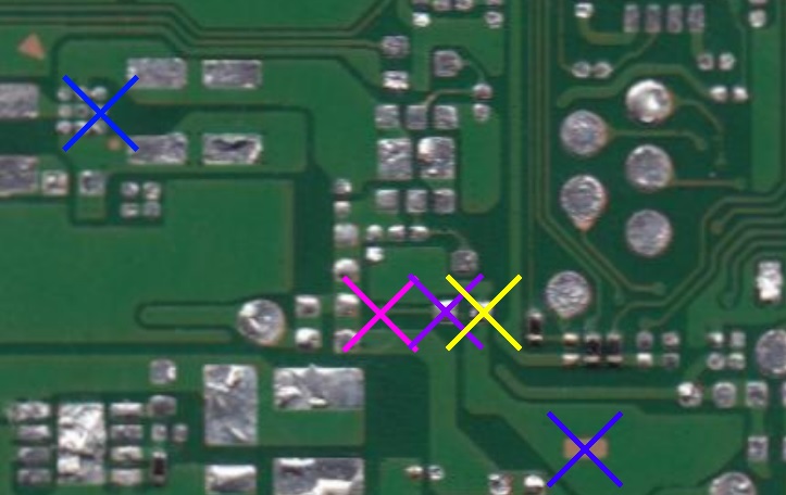
Yellow mark is connected to ground. I pick up EN on the purple marker. It’s one of the legs of the IC marked 42 which goes to the gate of PP5 dual mosfet. From what I understand it seems like it’s letting 8969 output through the mosfet when EN is present.
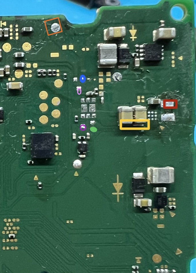
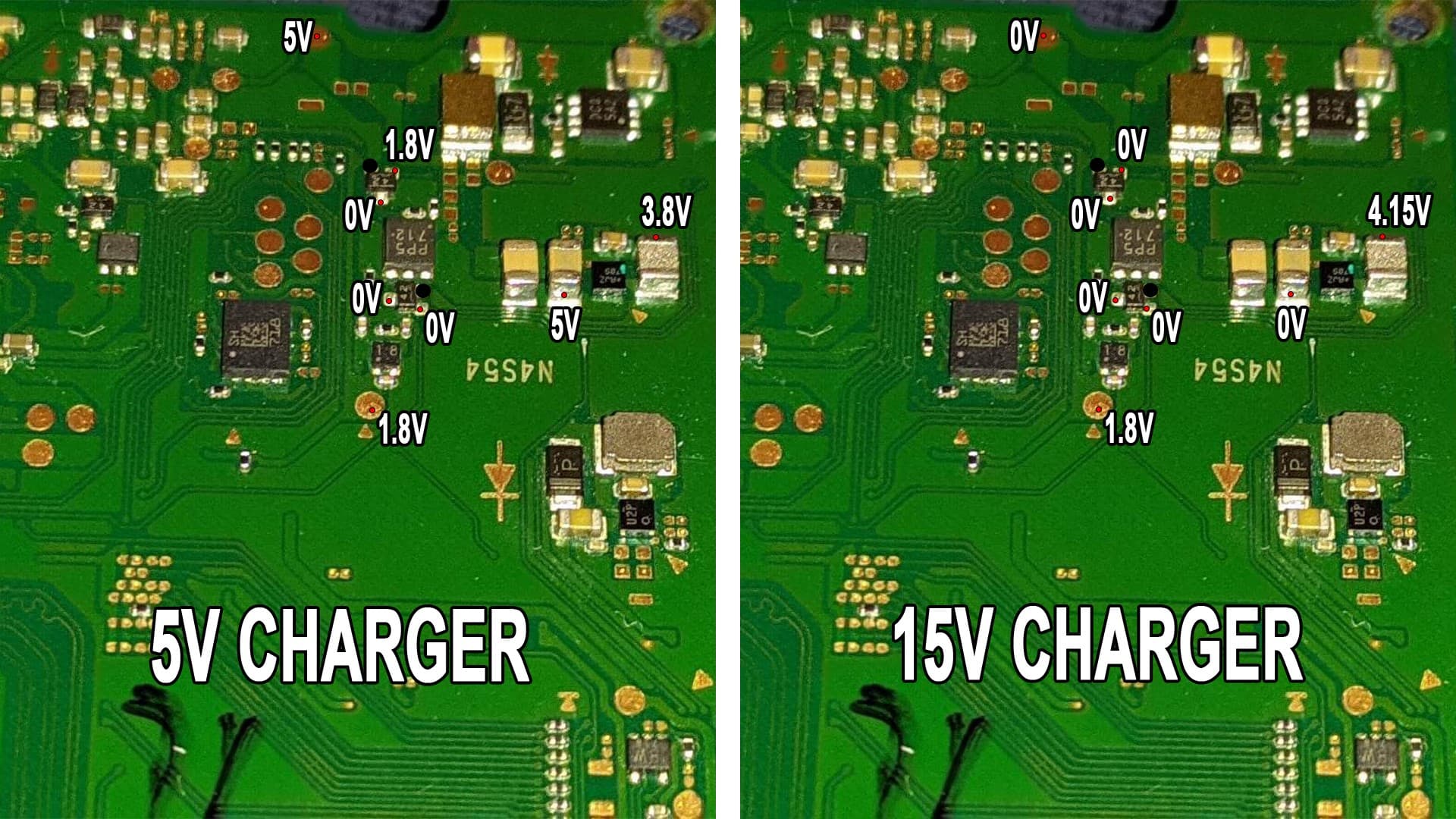
Good mainboard
Orange : 5v ( both pluged 15v and not pluged 15v charge) Your mainboard loss 5v if pluged 15V charge
RED : Vsys
Yellow : 5v( Nintendo Switch not plug 15v charge)
Blue : 1.8v → pink 0v purple 5v ( Nintendo Switch not plug 15v charge)
Green : 1.8v → purple 0v ,pink 5v , yellow 0v ( Nintendo switch pluged 15v charge)
May be little help you.
Sorry not good English.
Do you have telegram number?
Do you have any update regarding this problem?
I experience exactly the same issue.
Thank you.