I’ve been trying to fix this Switch for a long while now and I’m out of ideas at this point. When I got it, I immediately noticed the USB port was ruined, so I tried replacing it. This unfortunately didn’t go too well, since it was my first hot air station attempt - all upper row traces were torn off. I did however manage to connect everything as it should be and checked continuity with a multimeter - all seemed to be fine. The console still did not turn on. I opened up my working one and charged the battery of the dead one. It booted into error 2101. I’ve read that replacing M92T36 might help fix that, so it was the next thing I did. The error went away and the console appeared to be working, but it still wasn’t charging. What I found next was that there are these diodes on both sides of the board, that can sometimes cause a no charging issue. On the side with the CPU, with the port pointing upwards, they’re located below it, to the right, next to the shield. On the other side, port pointing up, they’re to the right of it, below the screw hole. Not all models of the Switch have them, and it was apparently fine to remove them, so I did. After this, it started charging, with both a phone charger and the official Nintendo one. The next step was the dock, and this is where I’m stuck. When I put it in, the dock light would blink very irregularly, the console’s screen would stay on and the battery would charge. I assumed it was a fault with P13USB, even though there were no shorts on it. I replaced it, but it made no difference. I then thought that maybe I damaged the chip or it was already faulty, so I replaced it again. What I didn’t notice, was that I accidentally moved a capacitor next to the chip in a way where it interrupted a connection. Port pointing up, there are two tiny, beige capacitors to the right of the filters leading to P13 - it was the left one of them, on the trace that leads to the first point of the right side of P13 (I would post a picture but there’s some issue with embedding). One point on the P13 chip also didn’t form a connection, although I cannot remember which one it was. I tested it like this - the console screen actually went off and the LED on the dock stayed lit, but the TV was not receiving a signal. I took it out and inspected what I did, finding the two things I described and fixing them. This brought me to the same point as earlier - flashing dock LED, console’s screen staying on and the battery charging. Does anyone have any idea what else I could do to fix it? I greatly appreciate all help in advance.
It seems that you have a short on your usb c lines. I would check first the visible row for correct values. Here you can use the testpads. And then the hidden row at the pi3usb ic. (diode mode, no battery, no charger, RED probe on ground, black probe at the pins)
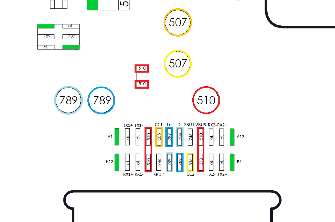
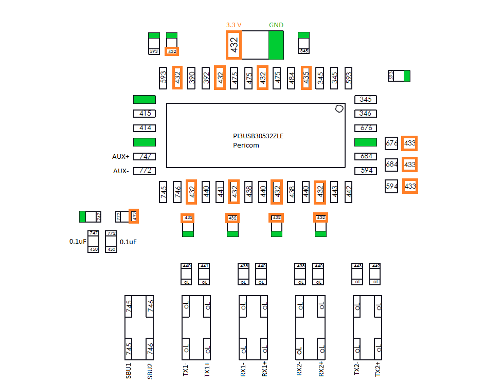
Thank you for the tip. Here’s what I’ve been able to measure (the space after https has to be removed - I’m not allowed to post links either, apparently…):
I don’t really know what any of it means though… I’ve tried getting a reading on D- but I wasn’t able to. I’ve also found that CC1 and SBU1 have continuity with each other, even with the port disconnected from them. Should that be investigated?
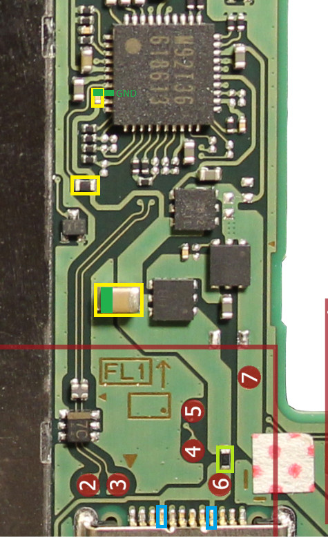
Above testpoint 2 and 3 is a esd diode (marking ‘7C’) and above a filter. Can you check if D- is there present?
CC1 and SBU1 shouldn t have contact. The CC lines are there to tell the m92t36 which way around the usb c is pugged in. And SBU lines are the Audio signal lines.
D- is unfortunately not present on either the diode or the filter. The filter has continuity. Any ideas on why CC1 and SBU1 might have contact? I’ve looked for anything obvious but I didn’t find anything.
Ok, my bad - I was checking if they have contact when the wiring I did to fix the traces was disconnected. I’ve removed the whole port now and they are not connected anymore (not really sure why, because the port doesn’t have a connection between them and I checked the wiring many times, but it must’ve been its fault). However, D- is still not present.
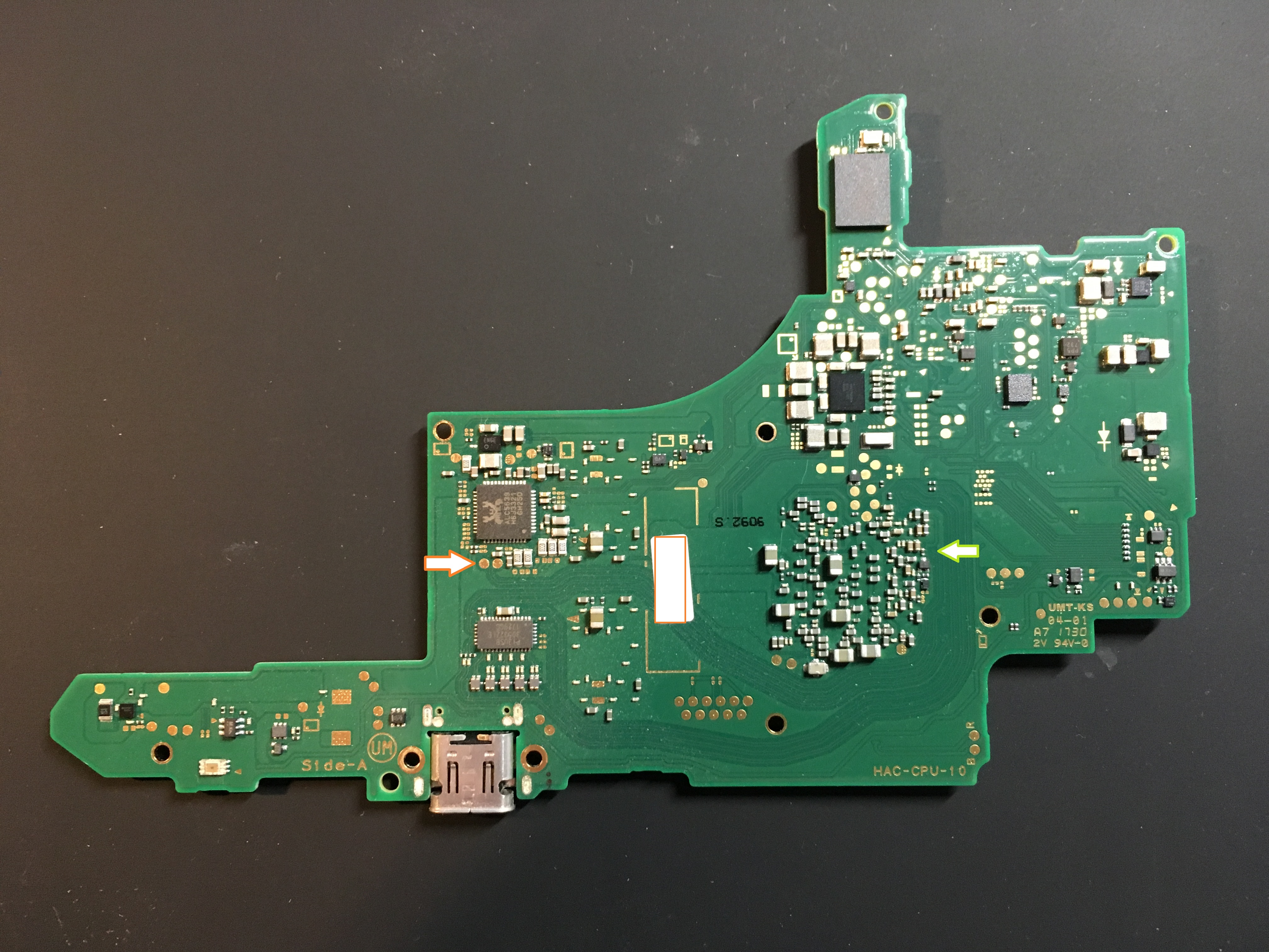
On the backside (side A) under the realtek ic are also two testpads for the usb datalines. I would check there for the right value and then follow the line to the point where it goes through a via (green arrow) to the soc and scratch a bit the soldermask at the via and test there.
Possibly off-topic, are these boardviews available anywhere? I have a Switch mainboard I’ve been planning on sanding+scanning to make a vectorized version of all the layers to help with things like BGA pins and inner-routed signals. It’d be great to have somewhere to put these towards if there’s already some work in this direction.