So, I have just finished putting back together the switch that had issues charging / connecting the left JoyCon that we got working a few weeks back.
For the most part it seems to be working well, with the exception that the screen randomly turns off. It can last from less than a second to a few minutes before turning off.
This is not the console turning off or going to sleep however, as if in a game you can continue to hear at least some of what is going on, such as the background music, and you can feel the joycons rumble when you shoot for example. It’s not all the sounds however, if on the lock screen you cannot hear the sounds while you press a button 3 times, but you do feel the vibration when it succeeds.
I have not yet had the screen come back on randomly, to get it back I have to press power to get it to sleep and then wake it up again.
As far as I can tell, both the back light and LCD turn off, but it is hard to tell.
I feel like I have seen a thread like this before, and I will have a bit more of a dig around, but does anyone one have any ideas?
Do you still get you +/- 5V rails at the 8316 when the screen goes off? if you don’t, do you get your 1V8 enables here?
Have you checked to make sure it’s not a dodgy power button flex by disconnecting the one plugged in?
maybe the backlight driver IC at fault or one of the surrounding components?
could also be the backlight ribbon at fault, think I’ve mentioned it before but I’ve had a lot of “new” LCD panels from China which are actually just refurbished and it seems as though they have just had new robbon cables [poorly] bonded back onto panel, these ribbons, especially the BL ribbonare of poor quality, the last panel I ordered had a break square across it (where the thicker portion is at the end)
final alternative might be a stretched out LCD connector, some of the LCD ribbons are thicker than others and it causes the pins/plastic to “stretch” or bend then the thinner rev LCD ribbon stops making proper contact with the pins so if you have another rev LCD/assembly handy, it might be worth testing that.
Ok, so when the screen turns off, the 1.8v enable, +5 and -5 at the screen are both there. The 33v at the backlight has gone however.
Some extra info however. After leaving it charging over night I found it on an error 2001-0114 error.
I installed the pending update to see if that made any difference. It lasted a bit longer (maybe random chance) but still occurred, however when putting it to sleep and waking it again it now orange screens.
I would presumably something odd on the wifi, though it connects fine and has managed to install updates and the Joycons work fine in Bluetooth mode.
I am going to try disbaling wifi in setting to see if that changes anything.
Yeah, that error and the orange screen would be consistent with a bad wifi IC, so I’d prbably replace
Maybe try airplane mode instead which truly disables WIFI/BT - though this doesn’t always alleviate orange screen issues depending on the fault with the IC
With airplane mode on, it was doing well, no orange screen after sleep… but then the wife dropped her phone in the bath, so have been dismantling that instead
Assuming wifi chip issues, but that wifi is working, would you think replacement or reflow?
It doesn’t always seem to affect WIFI/BT functionality, likely some other issue on the die
You can attempt a reflow first for sure, though from experience it’s most likely the orange screen will return and/or get worse
The only times where I’ve had permanent success with reflowing the IC is when it’s stuck at the second boot logo and hasn’t been causing an orange screen which seems to just indicate it was joint issues in those cases
Well the phone is apart now and has had a good IPA clean… will put back together once new adhesive arrives… I just hope the screen survived removal they are not cheap!
Ok, thanks for the info, I will go see if I can find some wifi IC’s for sale
So, i ordered new chips. The first i messed up by twitching during soldering. The second i got on, but wasnt entirely happy with how it went, and it booted but no wifi/bt.
At this point i removed the one from my donor, re balled and fitting seemed to go well but still no wifi/bt.
What do you recon? Reflow it again first i guess… if not remove and reball again?
This is the problem with these IC’s, particularly the ones from China, you start doubting whether they have been pulled from Switch’s and if not if they’ve been programmed for Switch… that the the reball jobs on these chips range from bad to simply tinned with an iron So I suppose this could be what’s going on in your case… hard to say
I wouldn’t bother tbh
I’d pull the chip from another donor just to rule it out, when tinning the IC, lower the temp of your iron to around 280C (or as low as you can go but still able to melt solder) and prep the IC and make sure it’s all even, following when using solder paste and stencil check the chip on edge under the microscope and ensure all balls are an even height. If still no joy then perhaps it’s the lines at the SoC end which are the problem
I would give you some points to measure but unfortunately you’d have to make an elaborate EMMC reverse adapter to get access to them on power on which is a bit of a pain, this would let you easily check for enables etc
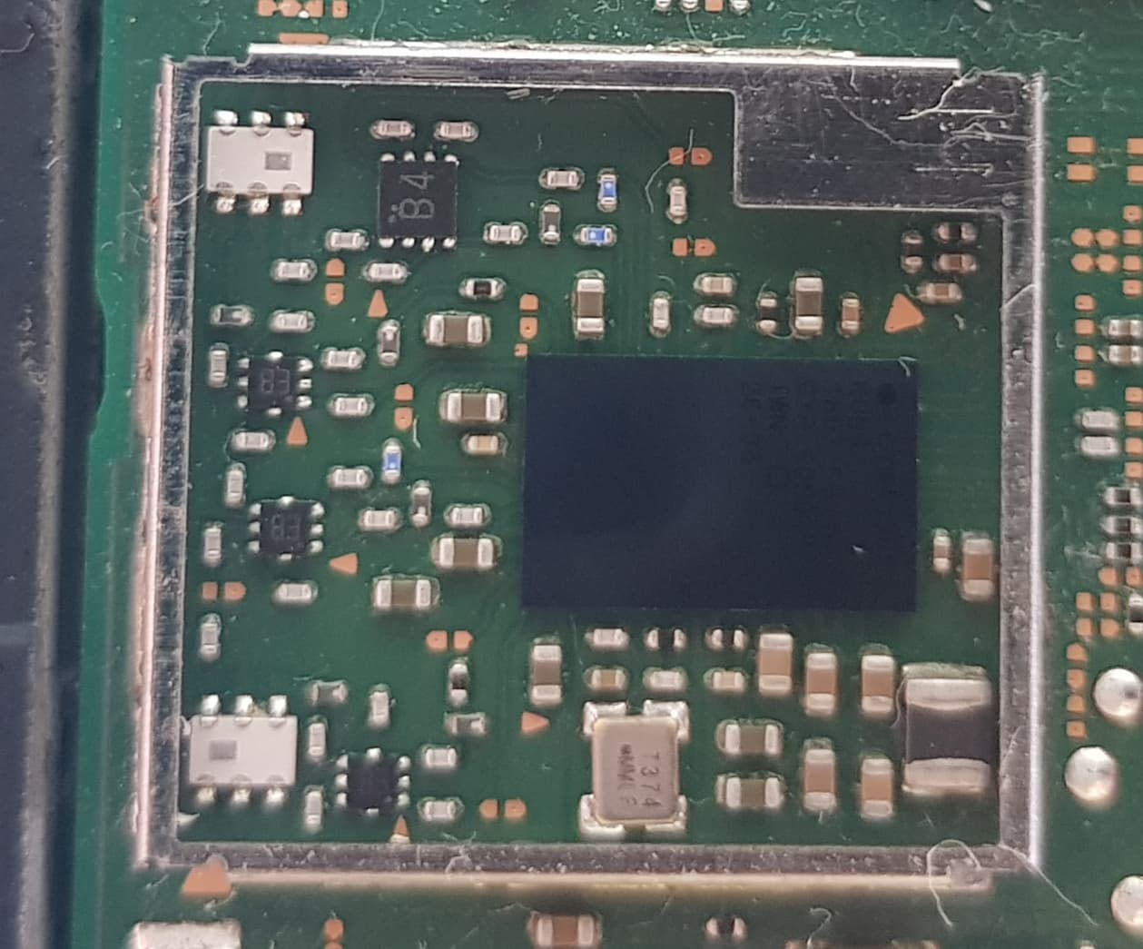
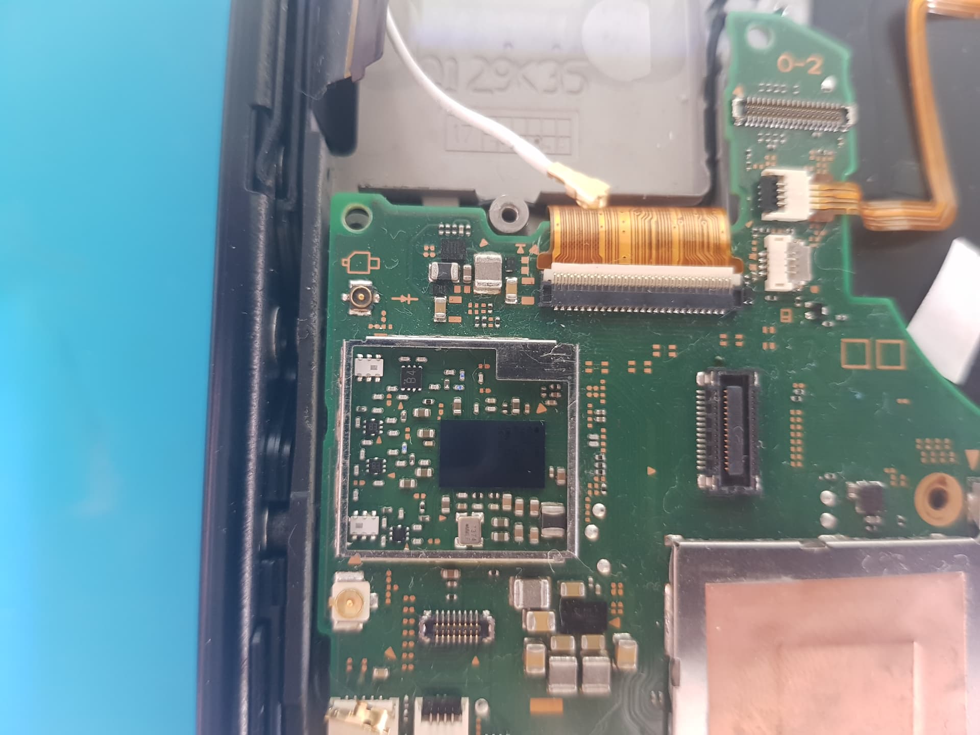
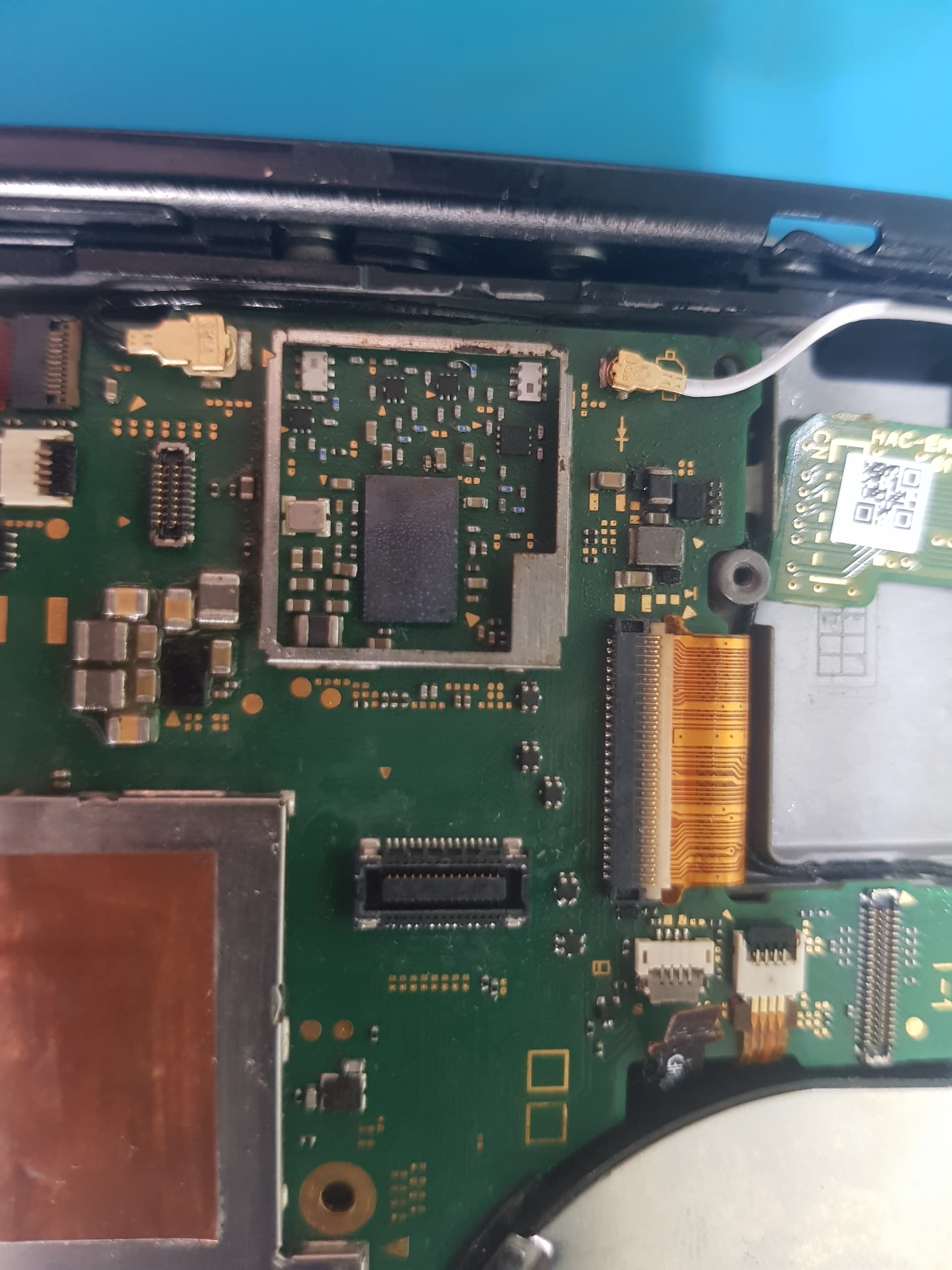
Before any of that though can you take a photo of the IC itself and around the outside of the shield frame?
Could do with seeing those TP and components to the right
I’d also take the opportunity to check continuity from the coax antenna connectors back to those 6-pin ICs, I have no clue what these IC’s are but if they’re bad you won’t get connectivity… though the chances of them both being bad are incredibly unlikely so probably not your issue
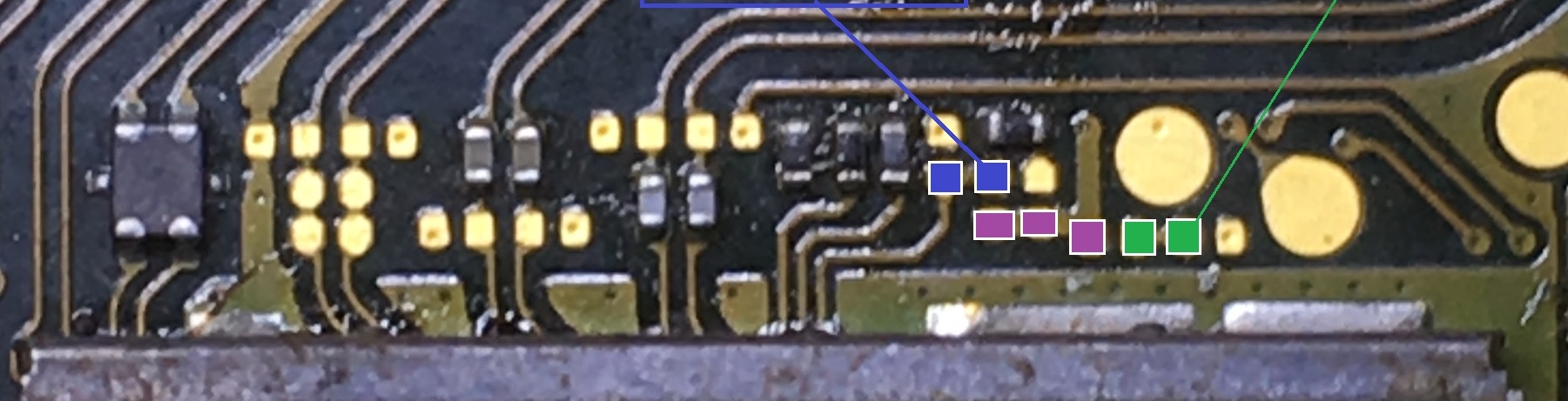
Failing that, you’ll have to tack some wires on at the following points and let me know the voltage on them with the EMMC connected and with the console prompted to boot
tbh I can’t remember what voltage exactly but purple is a bluetooth rail which I think is 1V8, blue and green are Wifi and Bluetooth regulation enables essentially so I’d guess 1V8 constitutes a logical high here too, if they’re missing or below the threshold voltage then it means the SoC isn’t telling it to turn on which would point more towards it being an SoC related issue
Cool, i will try and get that tested tomorrow. Given that wifi was working with the original ic (though with orange screen on wake) i wouldnt think it was soc? but worth a test!
Yeah this would be pointing more towards a bad install, bad chip, or a chip with the incorrect FW so provided non of the balls have merged below the IC itself you should be seeing those voltages present
Could also be you just got incredibly unlucky and pulled a bad chip off your donor too
I get 1.8v on the purple line while sat in RCM (its patched so cant boot anything). Will need jumpers to test the other two, which I haven’t got round to yet!