I already tested all these lines, except the one from the USB-C. All filters are good, continuity from top to bottom but not left or right, which as i understood is meant to be like that. From caps to P13USB is also good, i redid my joints several time, the point is that the behavior is the same as with the previous P13USB (i replaced it even though i haven’t found any shorts around). Will do a check from USB-C test board to filters to check. Thanks for helping me out.
The P13USB is notoriously difficult to refit correctly in my opinion. I think it’s a mix of package size and very small pad area means you need to get your solder distribution very even. Even something that visually looks right can be bad.
My biggest tip here is to remove all solder from the ground pad in the centre as this regularly can attract too much solder forcing the IC to float.
Before doing that, make sure you are getting the right orientation logic from the M92. You’ll find some square test pads to the left of the P13USB. I can provide the truth table if you need it. I’ve had an issue once where the P13 was fine, but M92 had partial damage and wasn’t communicating orientation properly. Both ICs need to be right for the dock to work.
Sheriff
Hi SheriffBuck, thanks, i reflow the P13USB 2 times and exchanged it once, behavior was identical after replacement. I also went to each single pad again and make sure the IC was making proper contact without any disruption. About that, i am almost certain it is ok, you even see the solder going up to the little side pad, which i assume is the proper way to do it. I didn’t get what do you mean about the table of truth for the orientation communication ? I understood that M92 was the power ic management of the board, but has he also a role in the HDMI topic ? I will try to find some documentation what are meant the ICs of the Nintendo Switch exactly, if you have some literature, that would be awesome. And yes i am ok to get your table, i guess it is readings in diode mode to each test pad right ?
I think the M92, along deciding what voltage to charge at, has a role in switching between the different sides of the USB connector. So it is possible that it is refusing to switch sides. I think in theory you could test this by removing the case from a dock and connecting it backwards, but if Sherriff has details on how to measure it that is probably easiest!
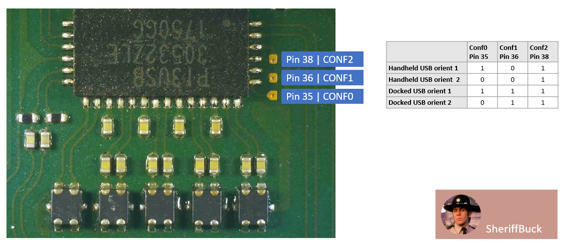
Sure thing. Here is the truth table and the test pads you need to check. Contrary to popular belief, the P13 is just an orientation switching chip that allows the Switch to accomodate the signalling changes required with the reversable USB-C design. It’s nothing more. Display Port signalling is generated by the Nvidia SOC and the P13USB simply handles signal distribution. It just a big set of double-pole switches.
For this to work, it needs to understand the current orientation of the USB-C connector. That information is provided by x3 discrete 3.3v lines driven from the M92 marked on the diagram below.
1 Like
I’ll add that to test you simply need to measure the pads with a charger connected to the board + battery. Reverse the charger connector to check the orientation pin. The M92 is a special for Nintendo and does some handshaking with the sister chip in the dock before enabling DP to pass through to the USB-C in “dock” mode. You will probably need to solder a flylead to the test pads to test that the dock is being correctly identified.
If you are doing repairs regularily, the ideal tool here is a USB-C extension cable that allows you to plug a raw board and battery into the dock (extension lead into the dock connector and then fly lead out into the bare board). That setup allows you to check if you’ve got partial functionality as sometimes it will work “one-way” but not the other. If you get one of these, make sure you get one that’s fully wired for video.
Sheriff.
Ok so, just to make sure i got your point :
- PIN 35, 36 and 38 should have 3.3V depending on the table in the picture, so for example on line 1, 3.3V on pin 35 and 38 and 0V on Pin 36, right ?
- Buy some female USB-C cable, plug it in the dock and use the male side in the Switch while measuring the Pins should indicate if M92T36 sends the correct orientation config to P13USB, right ?
Thank you so much for the awesome inputs, this is really more then valuable information.
Yes. That’s correct. The extension cable allows you to have the board accessible to take measurements. Alternatively, you can just solder fly leads onto the test pads and run them out of the dock to your multimeter.
Hello, I’ve been in a similar situation as original poster I think.
I’m thinking when you replaced p13 you delaminated the PCB,
which caused the 5v tracks not to make a good connection.
I found that if I applied pressure around the bq coil and the fuse then my switch would charge fine on 5v, (even without a p13usb in place)
I had to reinsert the cable a few times to get it to behave.
my switch onlys docked and charged on 15v but always ran into issues on 5v
my original issue was a short in p13 (replaced that)
once I got a new one on, it said unable to charge. but only on 5v
I think I did something to bq( can’t remember what) but the joycon connector looks burnt.
I removed the 6pin IC near the port. (the one which isn’t on every board)
i replaced m92 and the fuel gauge.
nothing worked apart from pressure above the usb c on battery side.
hope that helps
Hi Rip-it-up, thanks for the feedback, as i wrote in one of my previous post, number 3, i remade all joints around P13USB and then the charging operates correctly in 5 and 15V, fast charge both. There are no such issues anymore on that side. The only remaining problem is the HDMI output, which doesn’t work. Of course just to make sure guys, tested 2 working dock, on which my personal Switch, the one from my wife and the one from my son operates without an issue. I need to test Sheriff solution, waiting for the female cable, should be here tomorrow and we will see if M92 is the problem or not.
By the way, the Switch that i showed the ripped pad above is working perfectly after the repair  Really happy. At first, it wasn’t powering on at all, while i remember i turned off the Switch. Then i noticed that the person did gave it with Micro SD in, and what a coincidence, i watched one of the last video from TheCod3r where he bought a Switch for 105Pounds and it was stock on RCM mode. I told to myself that could be my problem as well, bingo, booting on Hekate and launching the CFW revived it. So much to learn around this console and repair in general, this is really an amazing topic really.
hello, yes I did reread your posts after I sent that message, so I realised that it probably wasn’t your problem, but I left it up, because I thought it might be useful to some.
There nothing worse than asking for help, and getting no information.
hopefully you can fix it.
yeah the cod3r is great I’m normally in the streams and I always watch the videos.
I have a few switches with a bad emmc actually, some or version 2 so I’m thinking of buying that hwfly just to revive them, but I’m not really a software person, so I’ll practice on v1s first
All right understood, i also read your topic before going for mine, because the initial problem looks really the same, but then i realized it didn’t looked like the same root cause.
Let’s see, waiting my female USB-C cable and will give it a try
I am finally coming back on this topic to let you know that the Switch is finally fixed. Thanks to all for your good help and advices. However shame on me really because after checking with a flying cable from dock, I noticed that in the other direction image was present on the screen. So I thought it is the M92 but before checking the 3.3v orientation signals, I wanted to check one more time the type-c and guess what, continuity on A11 wasn’t good and since I am supposed to read 0L in diode mode, no contact is also 0L…  I did the type-c one more time and now it is fully functional. I also found some leaded solder,Kester an Aisin, just for my knowledge, what the best fit in between 63/37 and 60/40 leaded solder for Switch repair? Thanks again
Either solder will work absolutely fine. I use 60/40 as it is easier to get hold of, I think 63/37 has a slightly lower melting point. (I think also the freezing point is different, but not sure).
Ok thanks, will play with both and see how it goes.