hope you are all doing good ?
I am coming back at you, sorry, trying to build knowledge, looking to a lot of videos and reading a lot of threads on the forum, but still i must admit that i suck in finding the issue by myself
I have got a Switch that has a broken USB-C port. Replaced it, so far so good, the console got charged and was working obviously fine. The only issue was no output to the TV from working dock for sure. I first attempted in replacing the USB-C again, in case of i screwed the soldering, but it didn’t change anything.
So i started to look for short and didn’t found anything in any of the main spot around M92, BQ and P13USB. I checked the filters, continuity is good and no short between left and right side of them.
As i was running without option, i tried to replace the P13USB. Now i end up in a situation where the console does still start, but won’t charge in 5V. It starts to take 0.47A and then gets down 0.09A and remain there. Console indicate that it is charging in the icon. I am not sure if i screwed something or if i got a wrong P13USB chip …
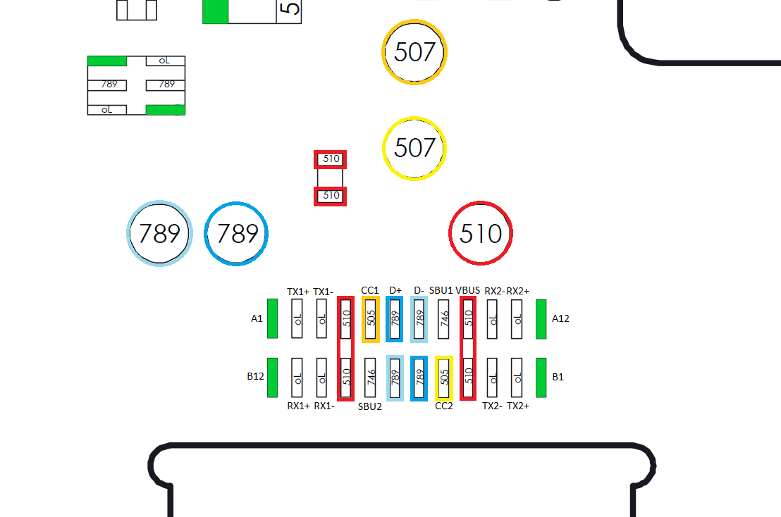
What i wanted to know is if from the diagrams i see on the forums, the value are taken in ohm meter with red probe on the ground such as this one right ? From what i understand on such diagram, the small rectangle around a chip are the legs on which i am supposed to read those resistance value, and on components i have either a ohm value, or short to ground (green), right ?
If it was charging ok before replacing PI3, I would start there, I hate trying to replace it as it is much harder to get a good connection for some reason… maybe the side pads are higher up, not sure. If you have sharp enough probes you can test for continuity from the side pads to where they connect.
Ok, thanks for the feedback. I remade all joints around the IC, now connection is good, charging operates correctly in 5 and 15V, but still nothing on the screen. If i go in settings, i can chose any resolution i want from the list or auto, the setting is applied, but i don’t get anything on the screen. Not sure where else to check.
Have you tested for continuity from the USB to the relevant points on the board using a breakout board of some kind? If not, I would say that is the next thing to try.
I took that one : https : / / www . amazon . fr/dp/B08DJ2XBXR?psc=1&smid=A1U9HA371QAC83&ref_=chk_typ_imgToDp
Will search the forum what pins should be used for hdmi output
Looks to me that you are on good way to success. Soldering these ports for somebody who doesn’t do it for life is kinda lottery. I tried replace mine first port about 5 times and there always was one leg not attached. Make sure, you prepare port itself - clean legs, check under microscope they are in line, add some solder so they will get connection as soon as they touch heated solder points. While soldering keep port close to hot air to warm it but not burn. Get one of USB-C testing boards to check every single line after all - northridgefix .com/wp-content/uploads/2021/05/3_test_boards_combo_usbc_micro_usb_lightning_northridgefix-1.jpg
Hi Davido, thanks for cheering i am doing my best at least. At the moment, the only thing i am a bit struggling with the port exchange is how to not melt the plastic part. For the legs what i do is that i lift a bit up the inner one, tin them with soldering first, and pre-heat the port before dropping the connector to it. But even with being careful, i always melt a bit the plastic. I am not sure if it is the temperature (390°C) or the air flow (on a scale from 1 to 8 on my soldering station, i am at 3.5). for the rest i also need a better tweezers set, mine grabs pretty much nothing (i ordered the mechanic one, like northridgefix by the way) and since i am in Europe, i only have unleaded solder which looks to be the hardest part compared to tutorial i see with leaded solder. I received my test board today, i will give it a try when the kids are asleep. Thanks.
It would definitely be worth getting some leaded solder, even if you have to order it from china or somewhere else. When doing ports, I just tin the pads (and sometimes the port pins, if I am having issues), put it in place, and then heat the area above the port, near where the fuse is, and just occasionally going over the port itself. Once I see the solder on the visible pins melt I put nudge the port around a little and put pressure down on it with my large ceramic tweezers before remove the heat and not taking pressure away until I see the solder solidify again.
Just ordered some Kester leaded solder in 0.6mm 63/37 with 245 flux in it, reference Kester 245 24-6337-8860, but this was pure luck to find in Europe, and i haven’t found anything besides shipping from the US some good solder such also as Indium. If you have alternative from Aliexpress, i am taking it because taxes to import stuff from the US are just ridiculous. Or if someone knows if buying from Amazon . com is including tol taxes or not ?
On the other side, i found on Aliexpress what looks like a “good” brand according to a lot of feedback, does anyone have eared from “Asahi” ?
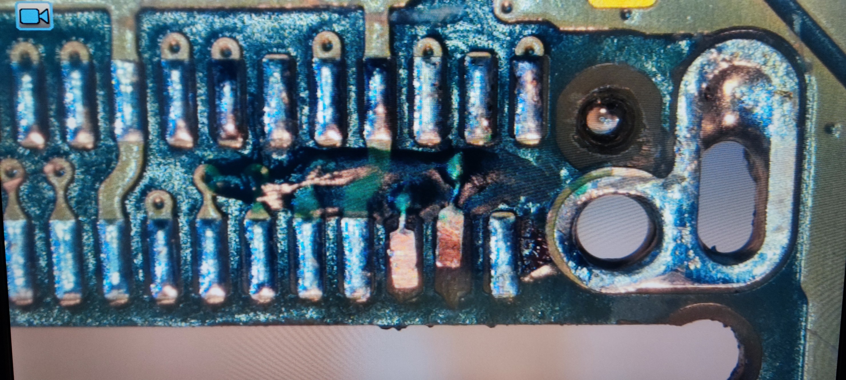
I just made my first pad repair from another Switch with also the no HDMI issue, but also charging with port in only one direction, this is the current result, i know i don’t have the right pad, but i am waiting for them since 2 weeks now and decided to move on anyway
Just received my test board, and i checked out the Switch that has no HDMI but USB-C done twice to make sure, this is the value i reported :
Pins
Expected
Measured
AB12
GND
GND
AB11
0L
0L
AB10
0L
0L
AB09
0,519
0,514
AB08
0,494
0,499
AB07
0,781
0,789
AB05
0,739
0,747
AB06
0,78
0,79
AB03
0L
0L
AB04
0,519
0,52
AB01
GND
GND
AB02
GND/NA
GND
This looks ok to me from what i have seen around in the forum and expected column is what i saw in one of the video from northridgefix youtube channel.
The assumption from northridge fix that both rows are indentical is not correct.
The readings may be the same but half of them are not the same line. Additional the pin counting is opposing. A12 and B1 are in the same corner and so A1 and B12. And not A1 and B1.
It’s important because I can not say from your measurements which ‘OL’ is missing. The both ‘OL’ blocks are eight additional data lines which provides the dp-data for the later hdmi output. A2 or B2 (can not figure out which you measured) should be ‘OL’. If not, you found your no-tv-out problem.
Hi Calvin, following your advice, i double checked my measure, and guess what, i missed one 0L you are right. New table with correct values this time :
The values are looking fine.
I would check for continuity from the test board to the pins on the mainboard.
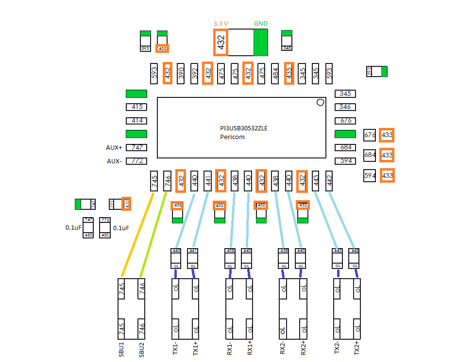
SBU1 and SBU2 could be tested from test board to the their pins at pi3usb. The other eight lines only to the lower side from each cap above the filters. And then the upperside of each cap should show a aprox similar readings.
My guess, you should find a faulty filter or a missing contact at the pi3usb.

 I will live with that i think