Hi all.
So what was just a simple SDcard port replacement turned into an absolute nightmare.
This is my first time soldering on a motherboard and I started out with some cheap equipment from Amazon. First off not causing any problems but not able to get any solder to adhere, the solder iron I got was useless and the heat gun I got didn’t get anywhere near hot enough.
The switch still powered on and worked at this point it just didn’t have the SD card connector on the board.
I then got better equipment, 450 degree solder iron and heat gun. now the solder adhered… And I was such a nooby that I thought I was doing a bad job when I just wasn’t seeing the solder had already melted and ready to join the connector. I used too much flux and too much heat.
Twice I had held the heat gun over the board for at least 30 seconds without moving the gun because I thought it needed that much to get the solder melted and connections made.
The other mistake I made is leaving the switch in the actual shell… Melting some of the plastic at the sides.
I’m not sure where it came from, mobo or plastic housing but when I did this I did heat it up till smoke came from under the board twice.
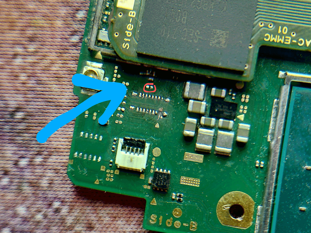
I also lost a resistor from just above the SD card connector in the previous attempt but it didn’t stop the switch from turning on.
I’ll attach some imagesbelow.
As you can see I also lost the switch connector port. And I’ve circled the resistor lost above the SD card port.
I removed the SDcard port I soldered on as I had lost a pad and thought it might be causing the issue.
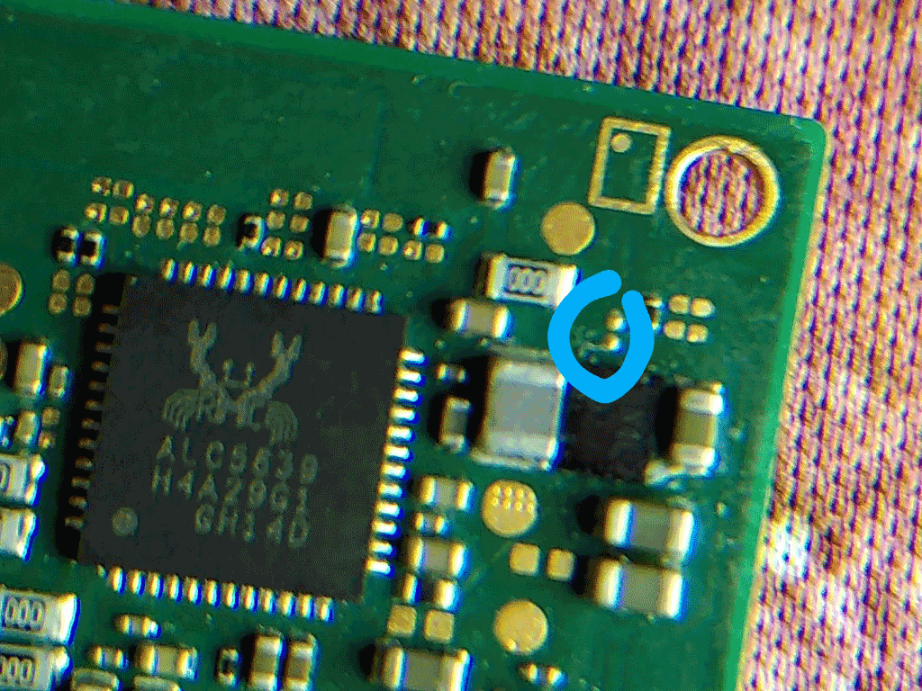
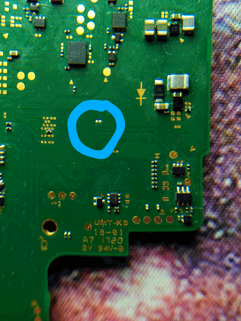
I have also circled other parts on the back of the board which have solder on them suggesting they are missing a component but not sure.
I’ve been watching a ton of YouTube vids and read a bunch of threads since. I have ordered heat shields and I have some copper pads coming to make repairs for the SD card port, I also have a better magnifying glass setup with board holder coming.
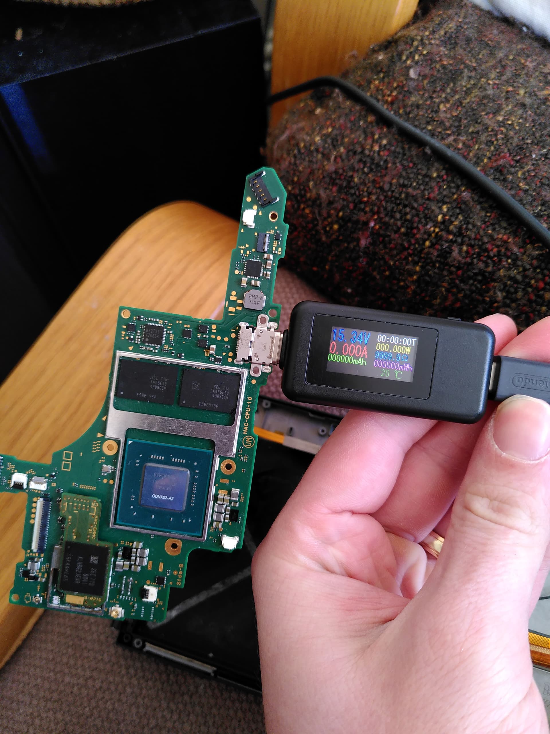
I have tried testing with multimeter in line with all the vids I’ve seen online but honestly I have no idea what I’m doing. I thought I had shorts somewhere around the m92 or bq but when I measure voltage with it on charge I get expected results.
However the switch goes straight to 15v when plugged in.
I’ve checked resistance and continuity but I can’t really tell if I’ve got shorts or not. I’m mostly seeing things as fine.
I won’t get a thermal camera but I’ve tried the IPAlcohol on components when turning it on and I thought the hottest parts were BQ and control chip on the back. Although the ram, CPU and the other bit that connects over the WiFi chip all get really hot too.
When I connect it to dock the green light flickers but goes away.
I feel like I’ve accidentally done a reflow and damaged components or shorted somewhere but troubleshooting and diagnosis is challenging. Any help and steps from where to put the black where to put the red level of experience would be incredibly helpful
Thank you.