Trying to fix the display missing on my nieces Switch and I can’t figure out why. I replaced the LCD connector and the Display Driver IC 8316 next to it. I turned the board around and when I heated it to replace the LCD connector a component must have fallen off. Anyone know what that component is? The backlight does turn on. The guys at GBATemp don’t have a diagram for components.

I think I figured it out. Found a post here where someone says it’s J and 2.5 or 2.6UF. I put in a 2.2UF since that’s what I have laying around.
Found a section here about testing power and I don’t have -5V or +5V. My board doesn’t seem to match up anyone else’s Switch diagrams, but I think I can figure out which is -5V and which is +5V. I do get 1.8V when I hit the power button. I had to scrap that trace to expose the wire so I could measure. What causes the loss of the -5V and +5V?
Another update, I reflowed the display IC and now I get -5.5V and +5.5V. Are those values off?
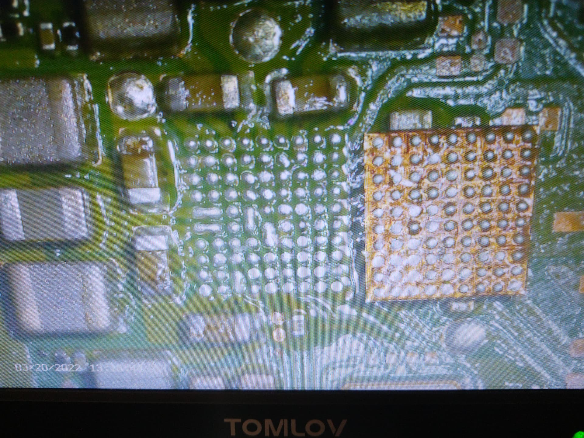
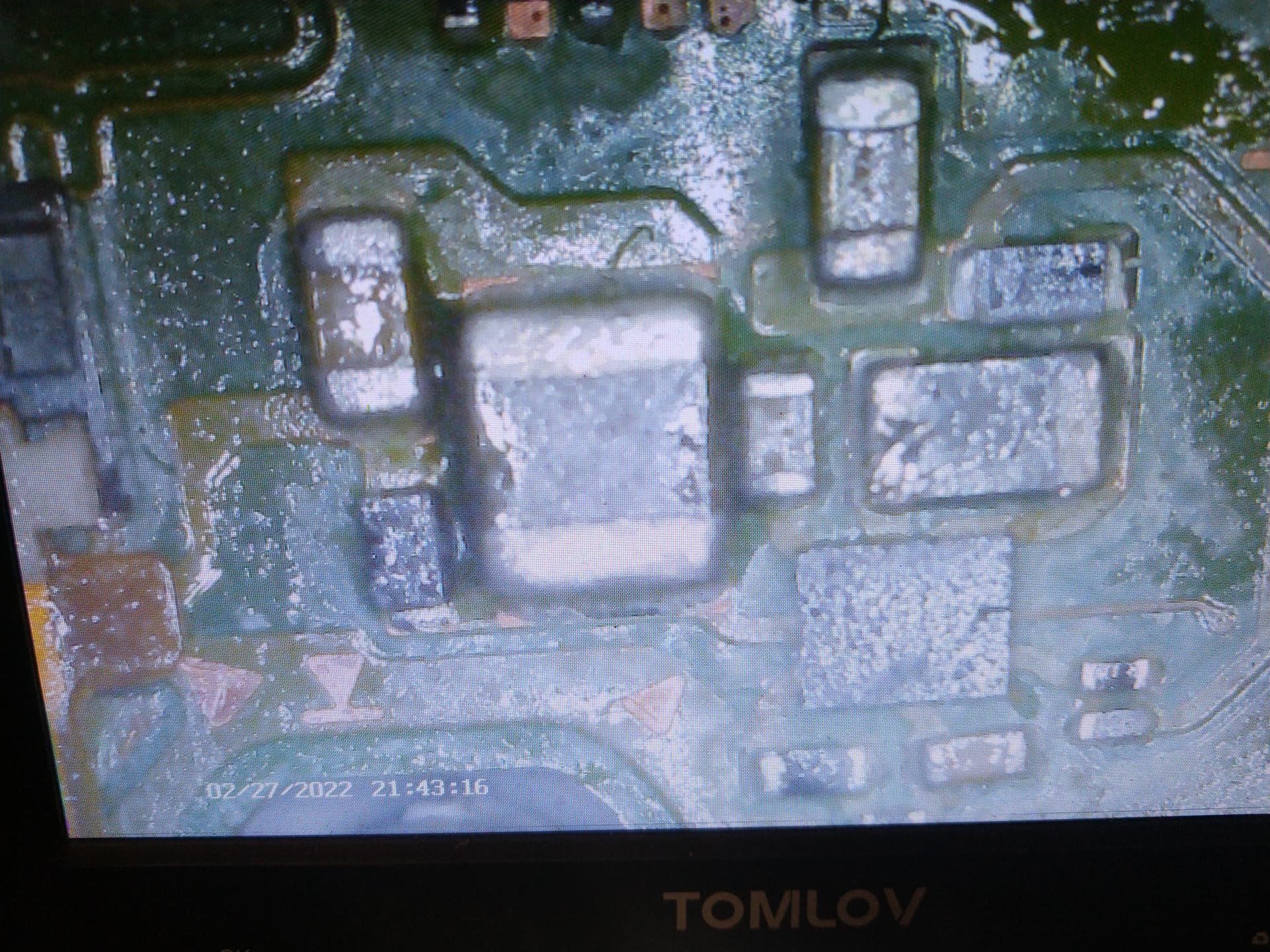
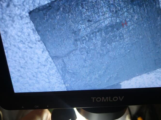
Another update and I got the display working. Turns out my lcd connector wasn’t entirely soldered. Before I figured that out, I was messing around and looking for signs of corrosion and found a bit around the MAX77620H chip in the back. Tried to reflow and accidentally pushed down on the chip, squeezing out the solder. I then proceeded to try and reball it, and then realizing I can’t reball for the life of me. I did replace it with a MAX77620A, and not a MAX77620H because instead of looking at the chip I took off, I instead looked online and see that it’s usually a MAX77620A and ordered it. I put the chip in and I see the Nintendo Logo and then nothing. Won’t turn back on unless I hold the the power button for 15 seconds. How different is the MAX77620A vs MAX77620H? Also, yes I’m an idiot.
Pushing down bga chips is never a good idea. ![]()
What is the issue at reballing the max chip?
I can’t reball it. Everytime I put the balls on and hit it with my heatgun, they either fly away or merge with nearby balls. I have a stencil to keep them in place, but the moment I hit it with heat it warps and some balls merge. I’m not exactly what one would call a professional.
I would put a thin layer of flux on the chip. Place the stencil on it and put the balls in place. Carefully remove the stencil and than use very low airflow with the hot air from high over the chip and getting step by step down closer to the chip or use a hot plate to solder the balls to the pad.
Is there an attachment to the soldering iron that gives you a flat surface so you can put the chip on it and the heat will melt it?
I have a little hot plate. It is more like this: MECHANIC IX5 ULTRA Vorwärmstation Layered Vorwärmerplattform Thermostat für Android/IPhone X-15Pro Max Motherboard-Reparatur - AliExpress 1420
1 Like
How you found it for $8? I just ordered it for $25.
![]() That would be a nice price. No, I think the $8 are for the inlets you can buy for different cell phones.
That would be a nice price. No, I think the $8 are for the inlets you can buy for different cell phones.
I got a MAX77620H and put it in the Switch and it doesn’t turn on. Nothing happens when I press the power button. Did I get the wrong chip? Websites say the MAX77620H is for Switch Lite, and this is a regular Switch. The original chip isn’t easy to read.
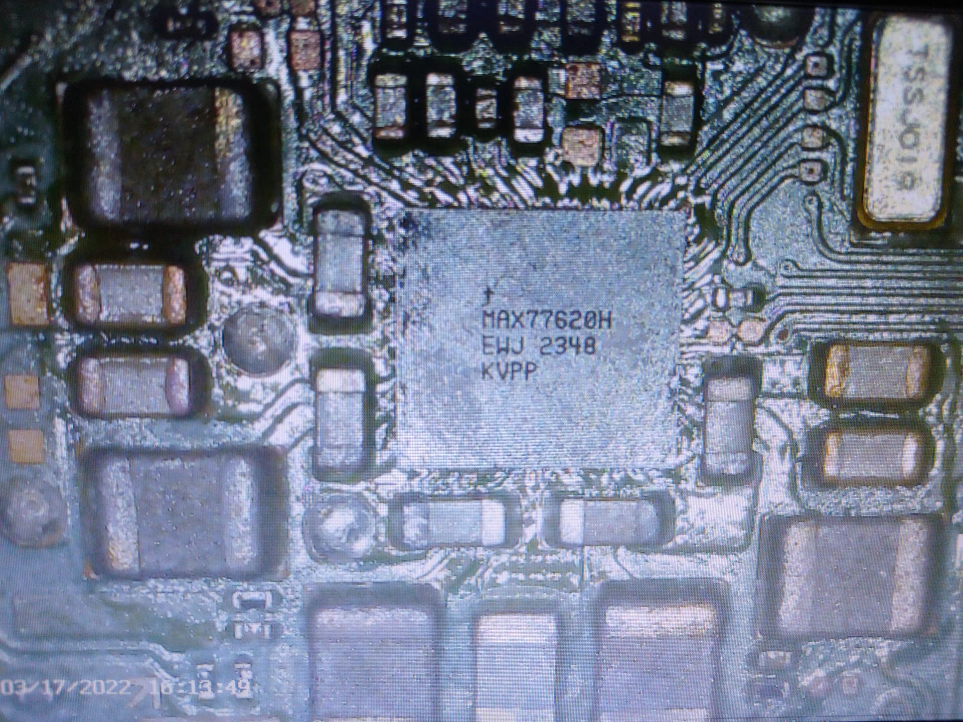
I tought the chip you ordered was the correct MAX77629A?
Decided to remove the MAX chip and I see a number of solder joints connecting to each other. I think I solder wicked too much and removed some solder mask. My diagram shows those are connecting to the same circuit, so that’s probably fine. That also probably hurt the connection to the MAX chip. Which means I gotta reball this stupid chip. Good news is the hot plate came I so I try to see if that method works.