Hi All,
Long story short: is there any docs on the values of most to all caps and resistors of the switch lite or how to test the SoC is dead
So short story long, I went to install a PicoFly. I only had a soldering iron. I installed the PicoFly using the ribbon cables (Deal4Go on amazon). I got the first ribbon that goes under the heatsink next to the SoC. The next one gave me problems.
I installed the 3.3v connection to the resistor, and mounted and grounded it. I soldered point B with ease as well. I struggled a lot with D and A. These are the ones connected to the 2 small circular pad and the solder on those small pads did not want to flow and stick with the ribbon cables pad. Both were tinned, and I used flux. I did finally succeed after using enameled wire from point D to the PicoFly because i think i broke the ribbon cables connection there. Everything else tested well with continuity but some places looked a little black i assume from soldering (all cleaned off).
The switch booted and showed I needed the SD. This was good! I flashed the SD and went to put it in and; im not sure how; the white clip that held down the daughter board ribbon cable was missing. I finally found it on the floor, tried to install but to no avail. I was able to start the switch to an extent. The PicoFly came on with a blue flash then a hwite flash then nothing. The LCD did not turn on. Prior to this, I got a blue white then yellow flash. Now theres not yellow flash.
I ordered a donor daughter board to take the clip from and resolder.I heated the clip to remove from the top and I couldnt get the click to come off. I ended up breaking the bad one on the motherboard into plastic pieces, but removed the daughter board connector with top down head. In hindsight i should have heated from the bottom and I learned that this day. This is still new to me.
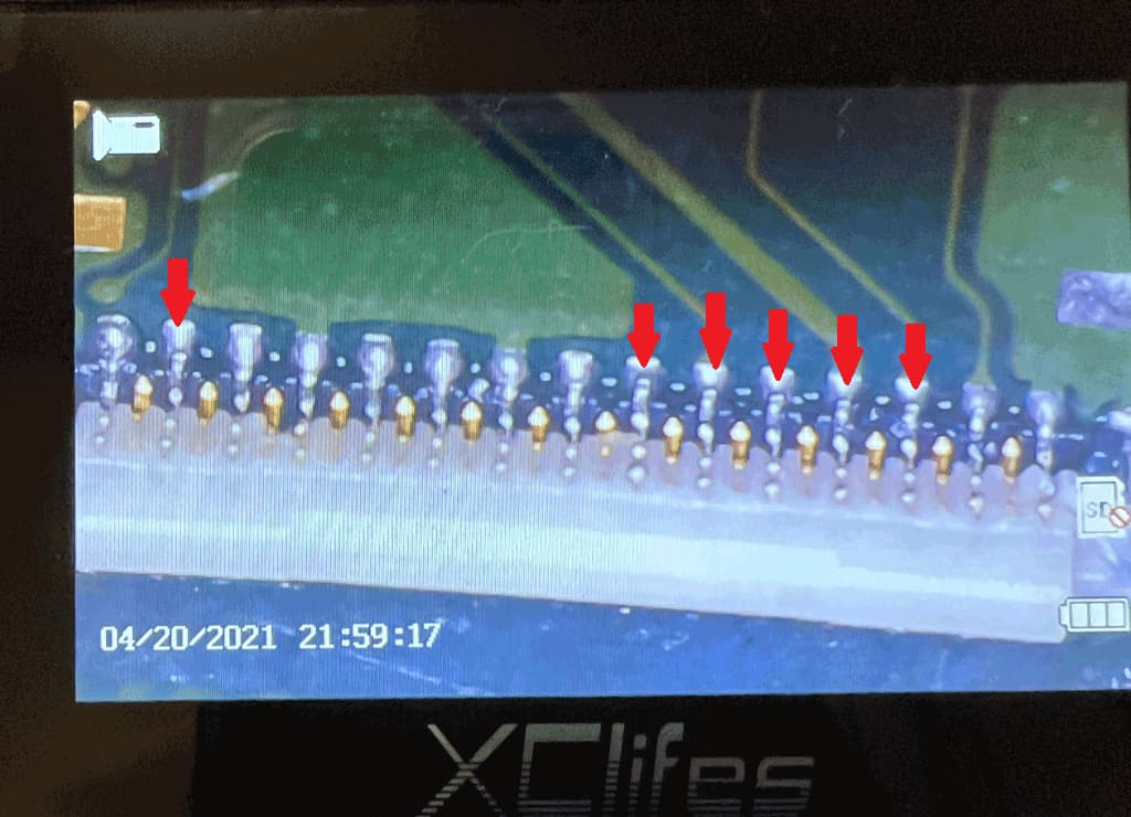
I also bought a new daughter board ribbon cabler as the other had a bent pin on it. Installing the donor connector on the motherboard happen i think successfully. I examined the pads and tinned them before heating from the bottom at 750F for about 2 min. It flowed and under the micrscope the pins look connected well.
When putting the new ribbon cable in, something started the smoke and burn from the connector as it didnt go in right. I took it out and the ribbon cable was burnt. I put the old cable back in and tested continuity. It was good. It still smells of smoke. I tested again and PicoFly gave Blue then white flash.
I removed the PicoFly completely but now theres no indication of power.
Does anyone have any advice of how i proceed to troubleshoot? are there any docs on values of spots or schematics?