While replacing the thumbsticks after my dog got ahold of them, I accidentally ripped the cable between the mobo and the right trigger assembly. Does anyone know where I can get a new one?
There’s not a lot of spares yet for PS5.
Maybe look on ebay for something similar size and pins? or even off a ps4/xbox controller?
Can you take a photo of the ribbon and tare?
Just so i can determine if the ribbon is using copper or carbon traces. If it uses copper, then the trace can be repaired directly if it uses carbon then you’d have to run a jumper wire from the origin all the way back to the relevant pin/pad of the connector.
If your handy with a soldering iron it should be a relatively easy fix… just lock your dog out 
The forum won’t let me embed a media file (I guess I’m too new?). If you look at TronicsFix’s YouTube video titled I bought the first broken ps5 controller at about the 1:19 mark it shows them.
It’s one of the ~1/2” wide cable ribbons going from the board to the left in the video while upside down but right trigger assembly.
When looking at Ben Hecks teardown on YT @ 8:24 when he flips the opposite ribbon over then it confirms that both (left and right) use copper conductors within the ribbon which simplifies the repair.
If you can upload a photo (imageshack(dot)com) showing the tare on the more copper colored side of your ribbon cable then i can advize repair steps
(imagizer.imageshack(dot)com/img923/9568/eq16Nb.jpg)
(imagizer.imageshack(dot)com/img922/4875/WFjS7v.jpg)
(imagizer.imageshack(dot)com/img922/7066/IcU3pZ.jpg)
The tear is pretty clean but I’ve never tried to fix a ribbon cable. Any help is very much appreciated!
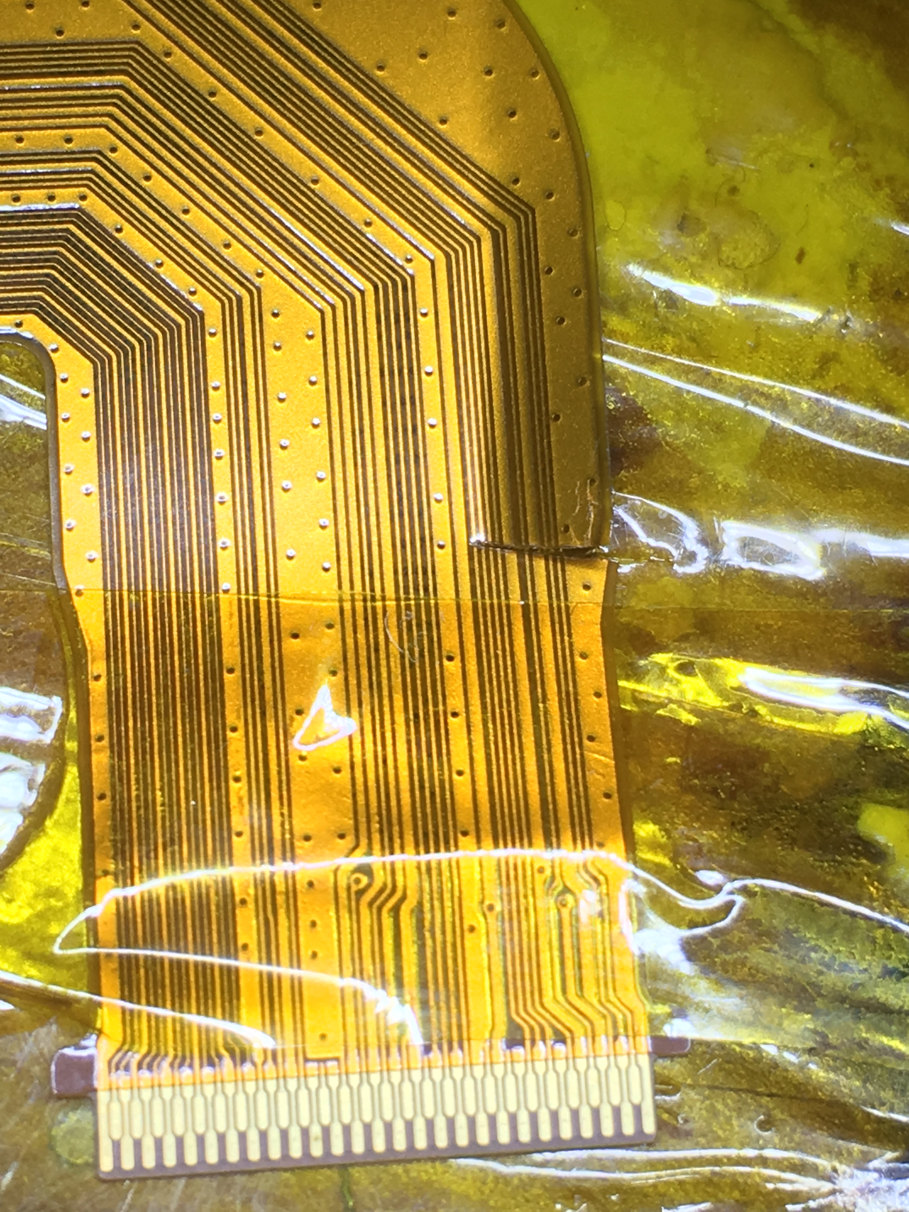
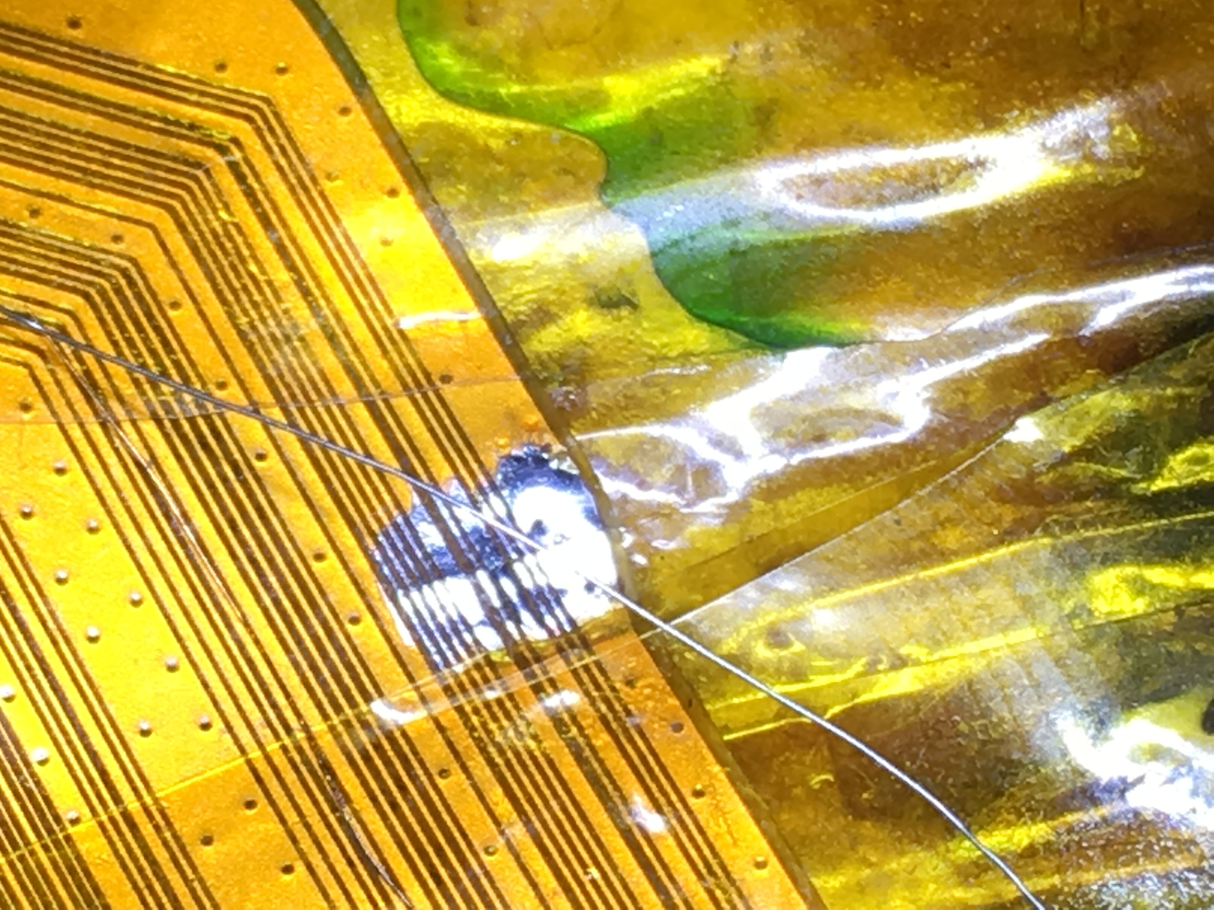
For demonstration purposes I’ve performed a similar task on the ribbon cable for a cracked nintendo switch LCD but it’s the same principle. Unfortunately, i don’t have a camera for my optical microscope, so you’ll have to settle for these poor quality phone shots, as i say though, this is for demonstration purposes only and was the culmination of about two minutes of work after purposely severing the cable, I would in no way consider the joints here as acceptable…for example i didn’t even bother changing my tip (using D24 chisel tip) whereas you’d want to use a finer point tip.
In this case, i just repaired the three larger traces on the ribbon for ease and demonstration but you’d do it to all 6 of your severed conductors on your ribbon.
Intentional sever/tare
Scratching back the Kapton esque polymor coating revealing the copper traces using X-acto/scalpel
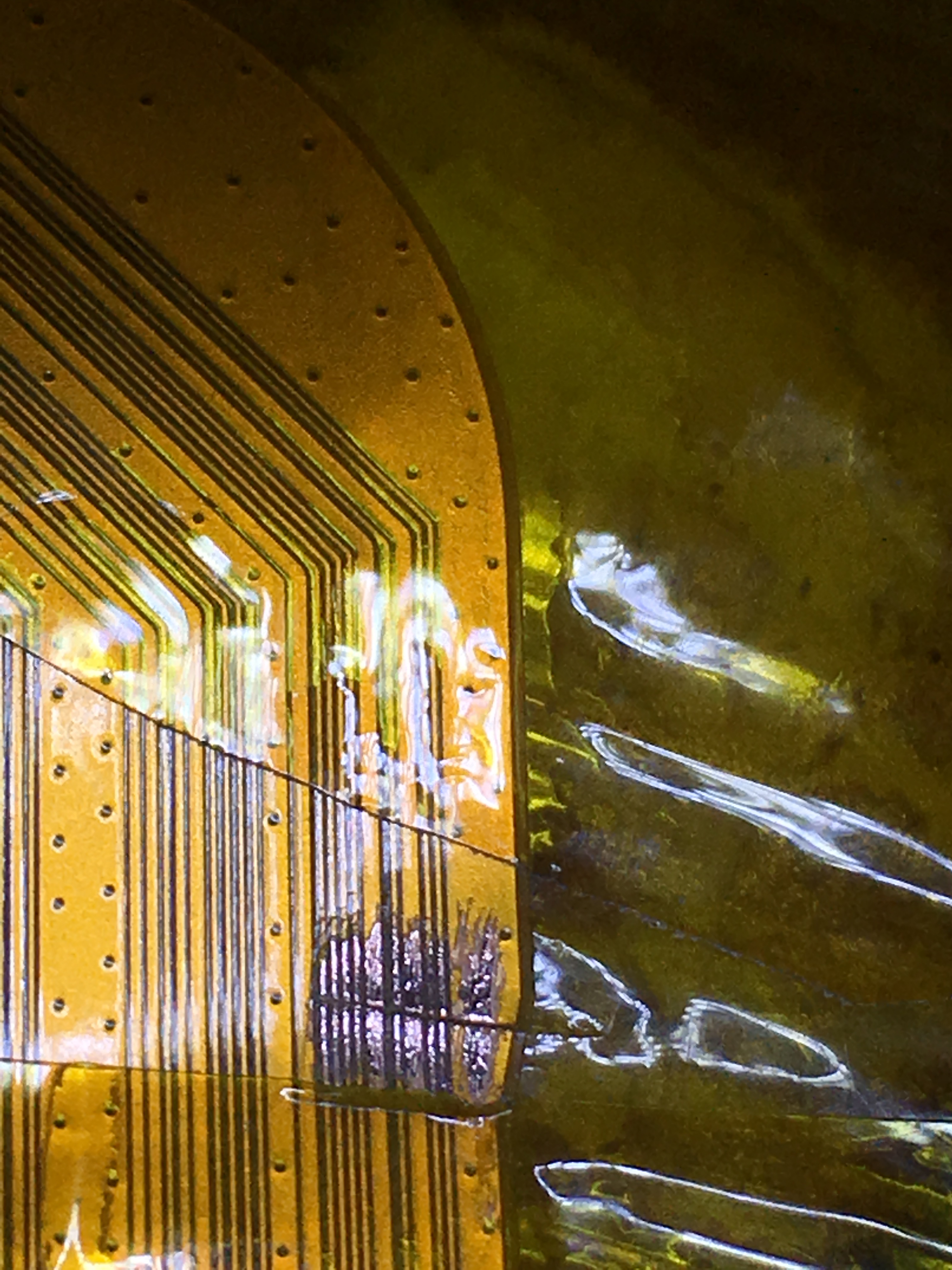
Flux, lots of flux
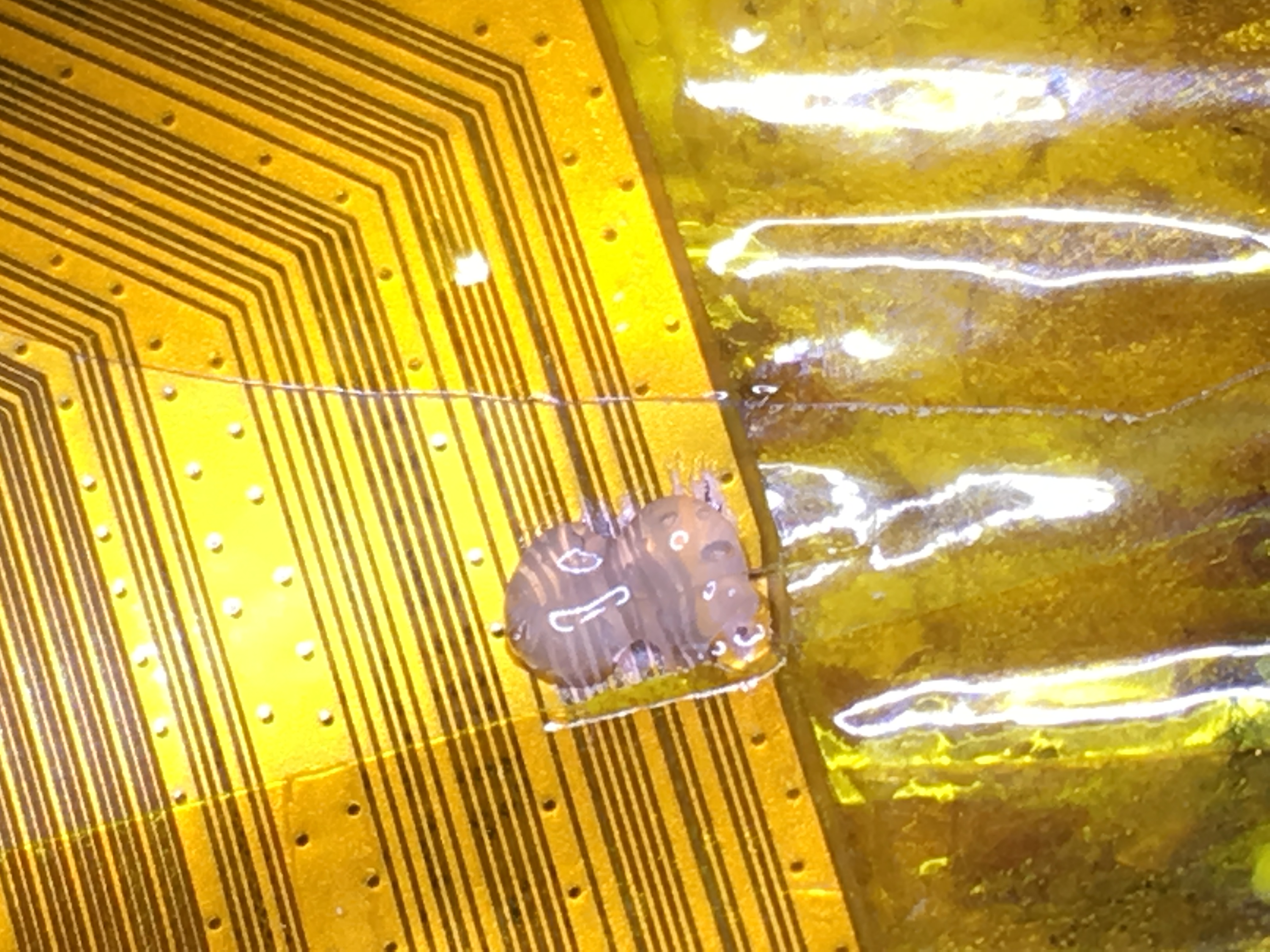
Tin with leaded solder, re-flux as required.
Select an appropriate sized conductor to bridge the break, use a strand from multi core cable, ensuring diameter of strand doesn’t exceed trace width.
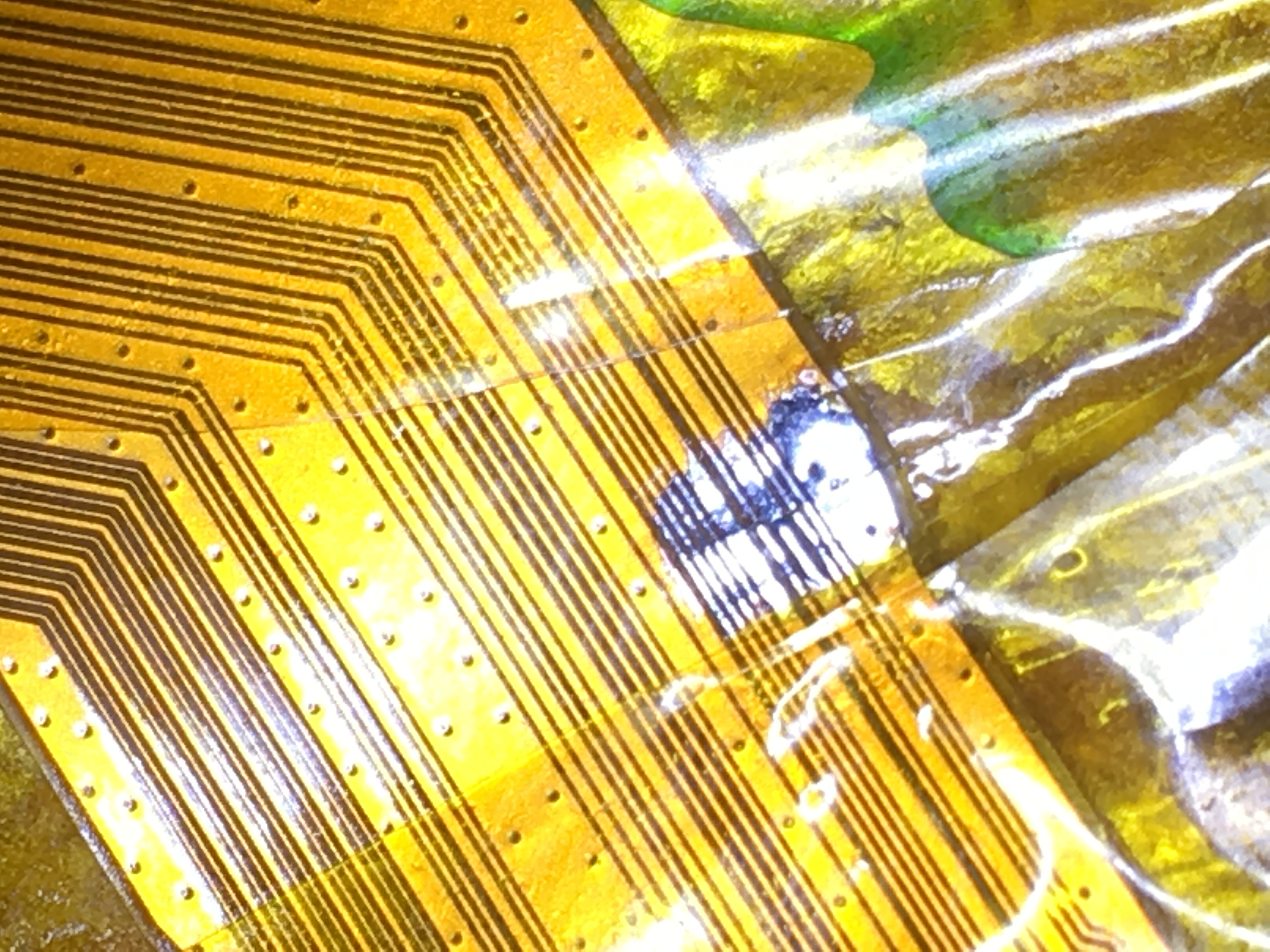
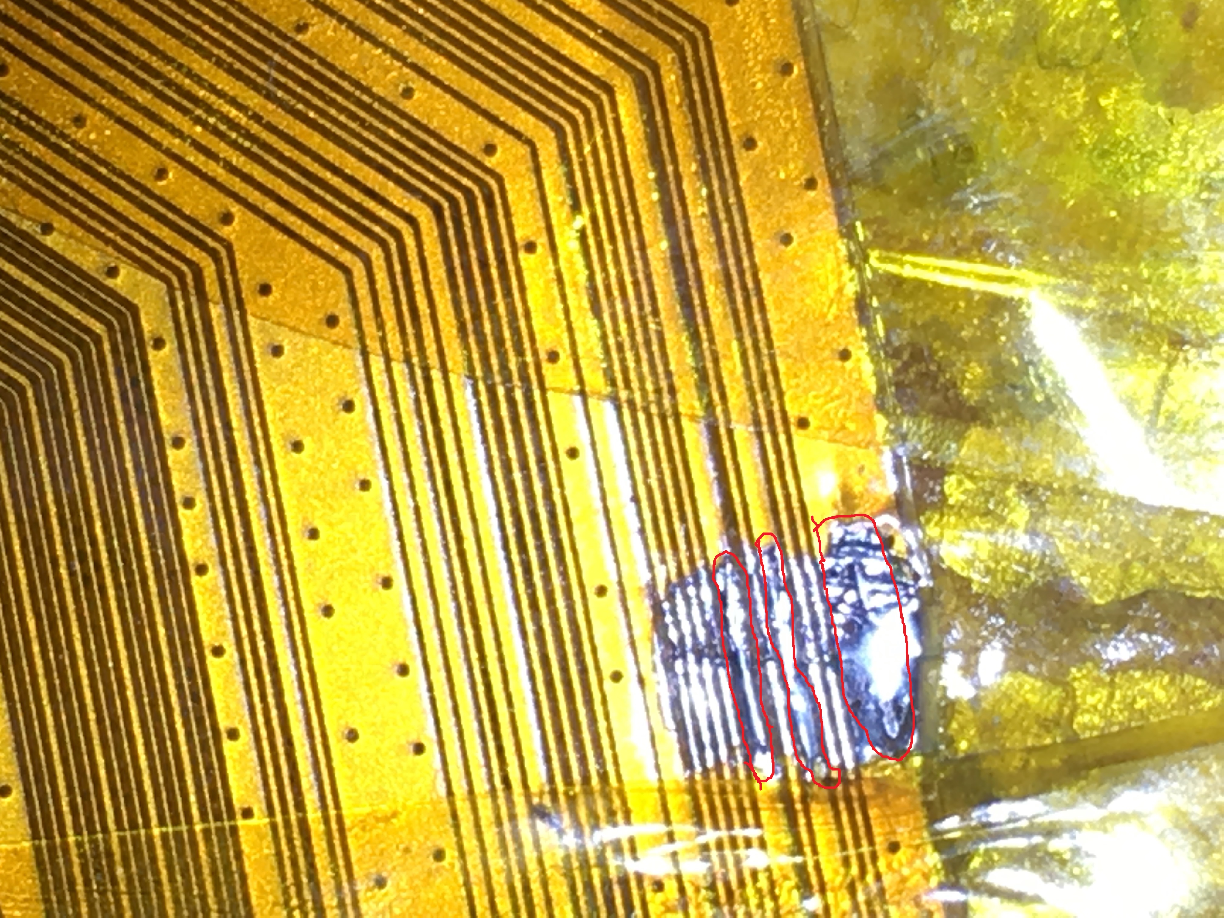
Then solder the wire accross onto the tinned ribbon traces being careful not to bridge to the trace next to it. In your case, I’d recommend repairing the finest traces first, then applying UV mask, then coming back after and finally doing the larger traces, this will reduce the risk of knocking your previous repair off or bridging. I’ve highlighted the conductors I’ve repaired/bridged here as it’s not clear from the photo because of quality.
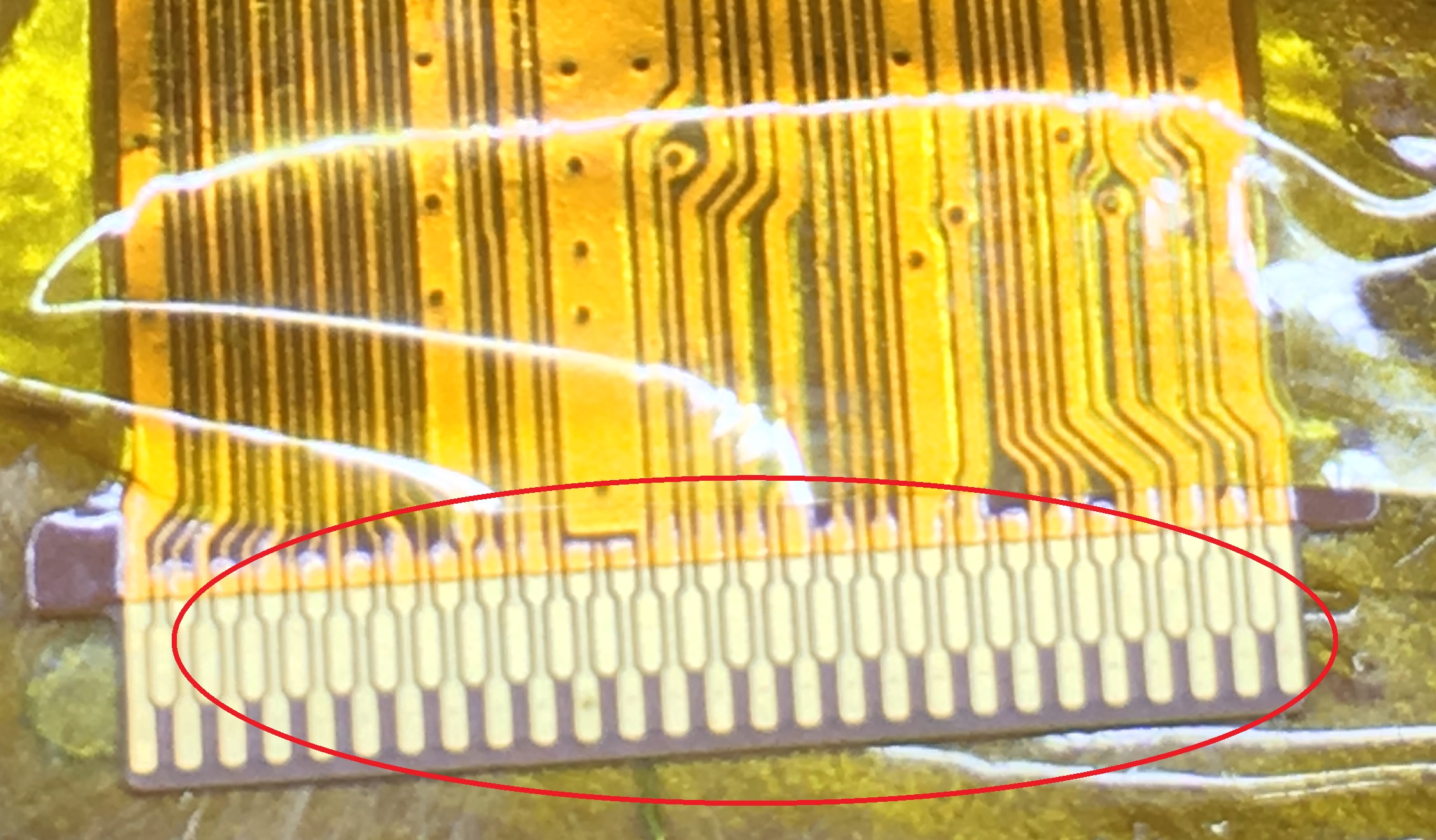
Next you want to test that the traces aren’t bridged from one to the other and that theyr’e making it from one side of the ribbon all the way to the other, do this by measuring the corresponding trace pad at the end of the ribbon in contunuity mode on a multimeter
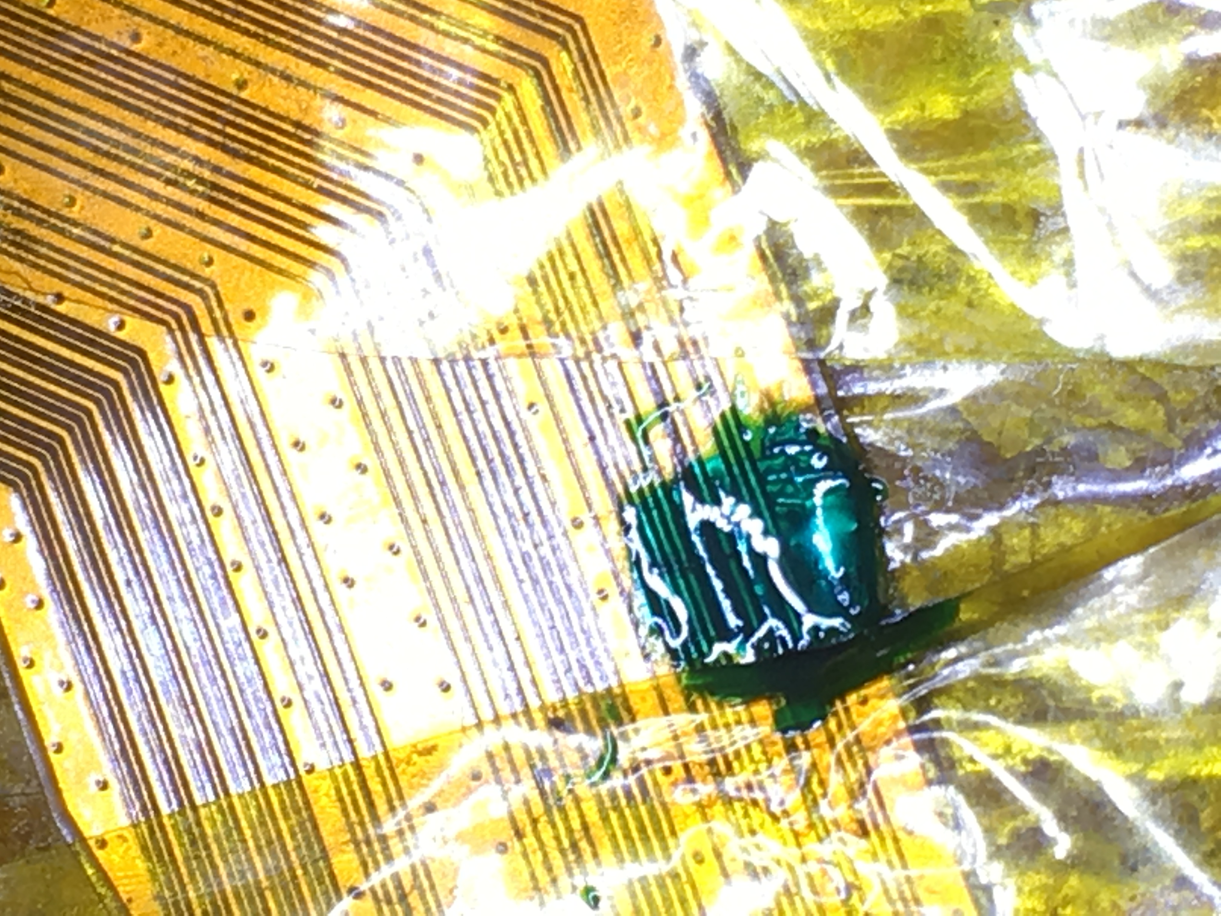
If all is good then finally you can coat with UV curable conformal coating and cure.
Hope that helps, It’s recommended that you practice first on a scrap ribbon from something else if you haven’t done this before and get some practice in
3 Likes
Thanks for all of the details and photos! That most certainly will help me out. I’ll give it a shot on another ribbon or two for sure and if when I get it to all go well, I’ll get it fixed up!