And now I can’t even enter RCM mode any longer…
I don’t have a usable donor board sadly. The only donor board I have is snapped in 2. I already salvaged the eMMC of that broken board to rebuild a NAND for another switch. I’m pretty sure the APU on that one is okay. I could try to transfer it to the BSOD board. Of course, I wouldn’t have a matching eMMC and APU, so i won’t be able to access the eShop (providing it’s revived). But it’s better than nothing, I suppose.
Trouble is I’m thinking it’s the board which is the primary issue, I get the feeling you’ll transfer the SoC over and find you have the same/similar issues.
That makes sense… Also, I was taking a look at the pictures I took when I first got my hands on that board. It had obviously been reworked, as one of the speaker connector is ripped, and there was signs of flux on the metal shielding between the SoC and the RAM, indicating a possible priori attempt at reflowing/reballing the SoC.
I should try to get a donor board and do as you’ve suggested, just to get to the bottom of this.
I see. Yeah this seems pretty common on boards which BSOD, first thing people do is try reflow the SoC… often times making the problem worse, sometimes SoC/Ram not even initially responsible for the BSOD etc… bit of a shame, maybe too, they did it in chassis and if the chasis had a bend that would cause some of the issues I mentioned earlier.
Given you can’t get into RCM state currently it does confirm my board theory as I imagine you have open lines at the SoC to board, which basically tells me the board has joint/trace damage or warp preventing your solder balls from making contact.
Hey there,
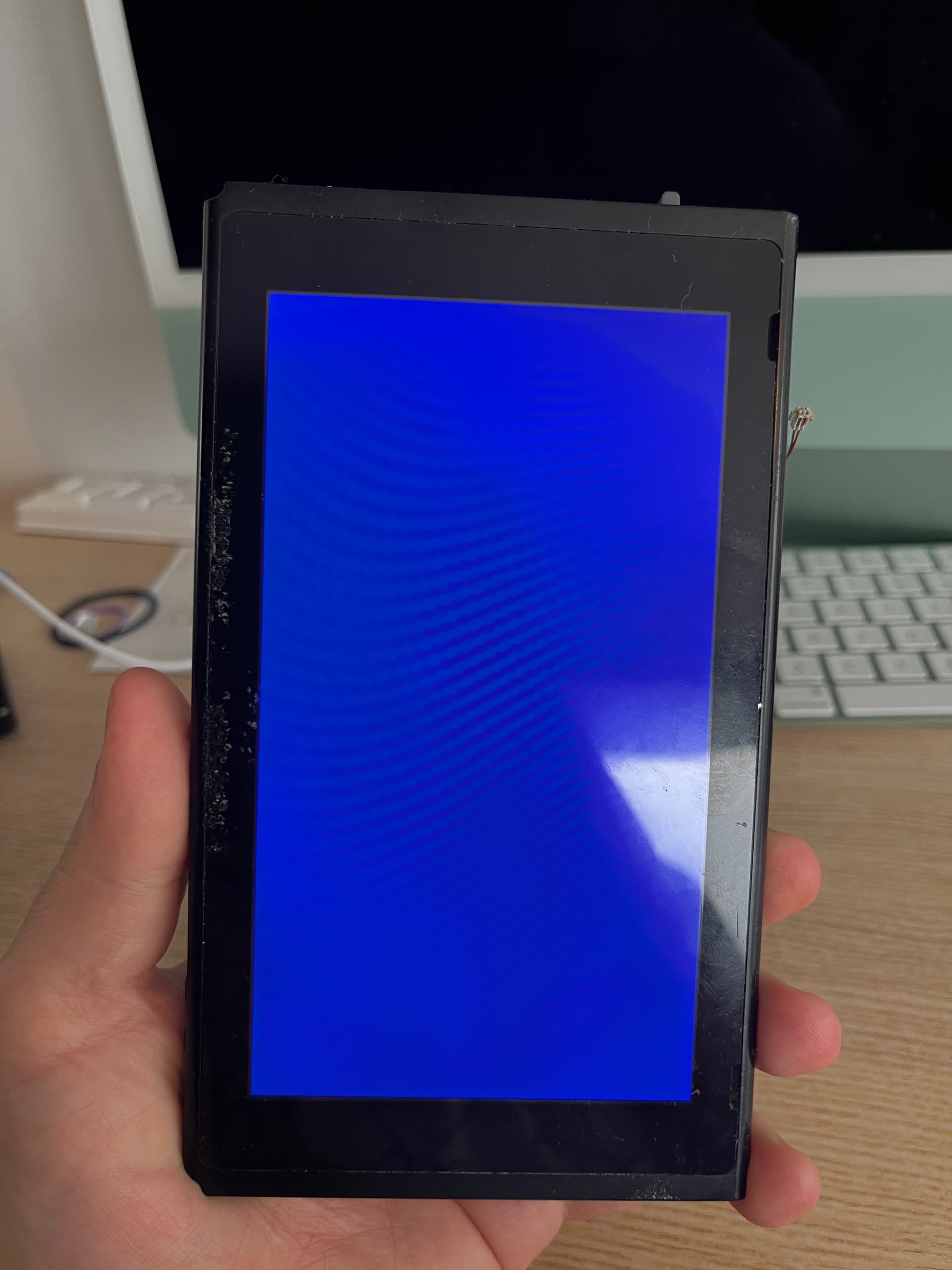
So I got my hands on another blue screen motherboard. It’s a v1 as well, and it looks like I have the same behaviour: I can get some payloads to work (biskeydump but not Hekate).
Pressing on the RAM chips or the APU doesn’t do anything. What are the odds that I get two boards with what seems to be the same unusual issue?
Before reballing the APU, I’d love to rule out potential other causes. I’m still working out a “process” to do so. Any advice?
Unfortunately this is actually quite a common issue, and I’ve conducted this repair many times over the years, it’s just because it’s a handheld and as such is far more prone to stress , either be it general or more severe case warp (i.e the old banana) that and the age of these nowadays, this wouldn’t be a common occurence of the fixed/static big boy consoles.
Checking resistance to ground on your primary rails which I think we’ve talked about before. This is my first step on any board outside of a prelim visual inspection.
Also worth noting, could just be a Ram issue or Fuel gauge issue in the case of BSOD, but you’d ordinarily be able to boot into Hekate (assuming it’s actually unpatched) in the case of a fuel gauge issue and more often than not you’d be able boot into Hekate or at the least Biskeydump in the event of Ram issues (though there are exceptions to this rule)
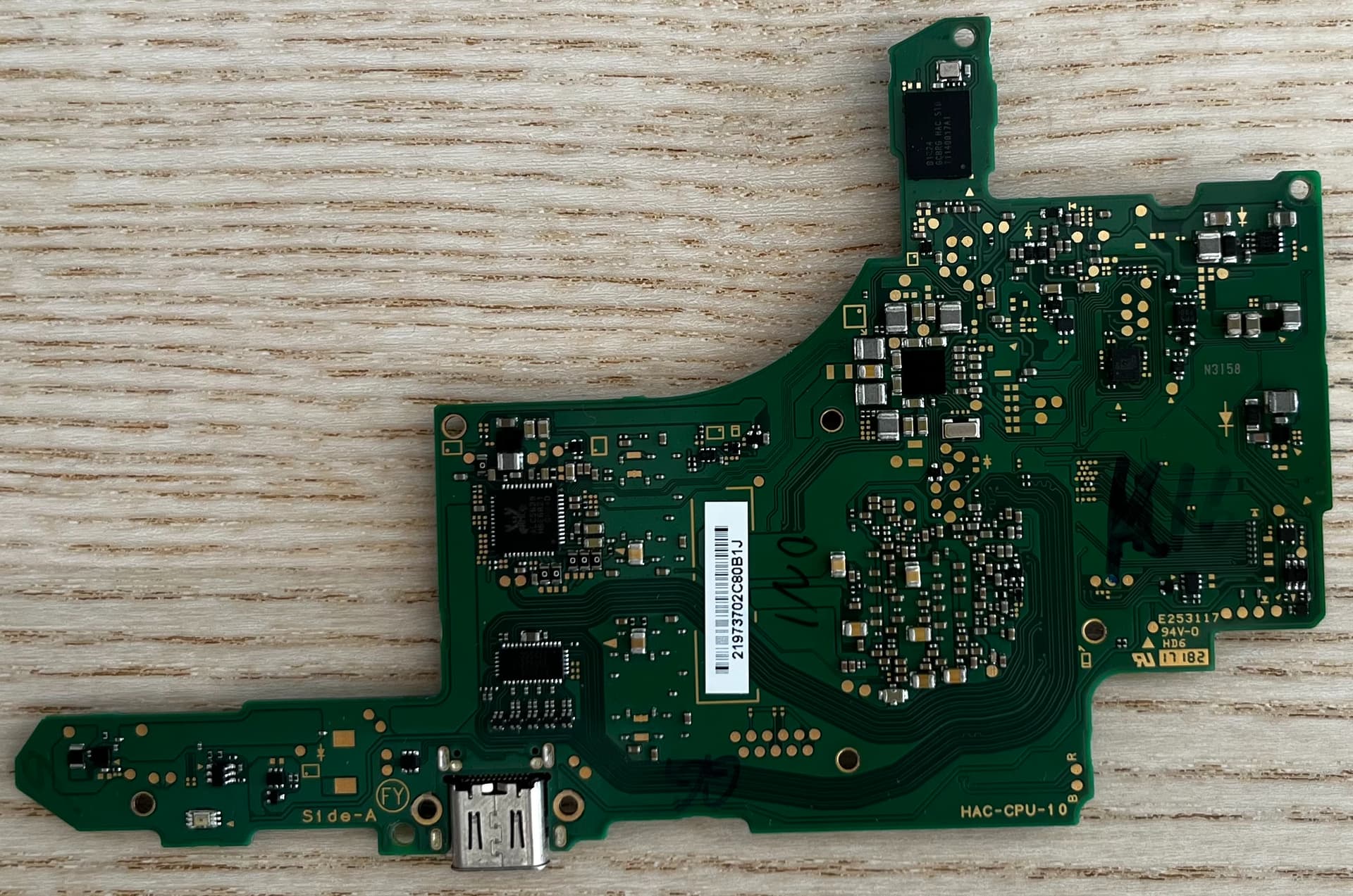
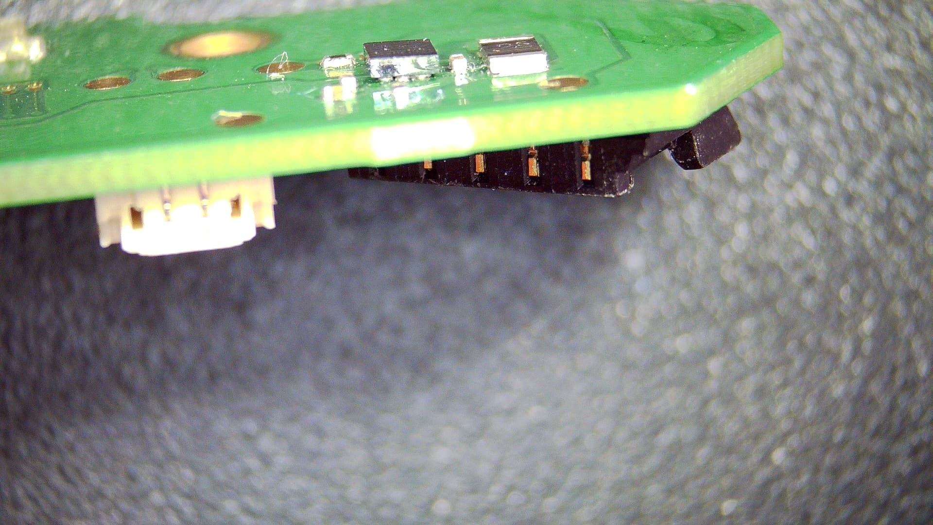
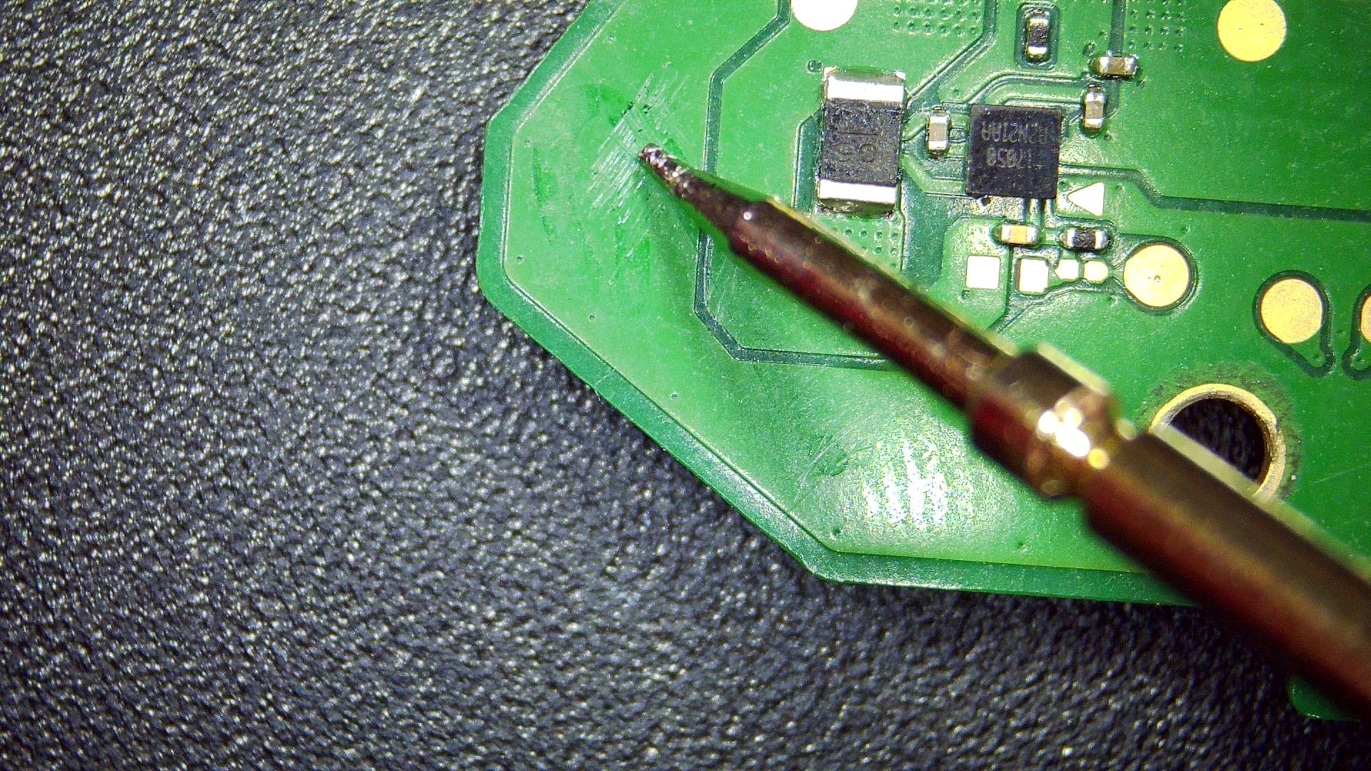
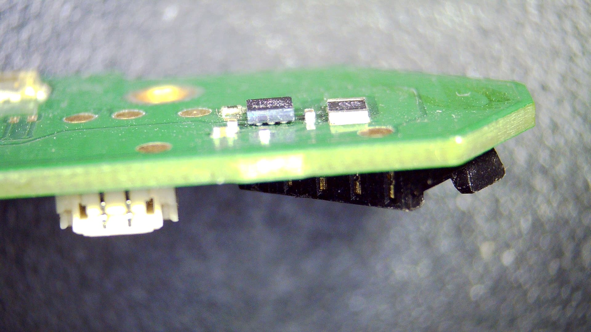
Also, when you did your visual inspection of this board was there any signs of prior rework anywhere? if you suspect yes then might be worth positing some pics front and back of the board, high res please, something might jump out at me just incase we’re going down the garden path with a potential SoC / joint related issue.
It had been open. The APU shield had been removed and there’s was blue sharpie on the edge. The SD Card connector was thrashed, so I replaced it. The board isn’t bent and everything else looks factory to me.
I’d check your primary rails resistance to ground as mentioned just to rule anything out or point to a potential culprit.
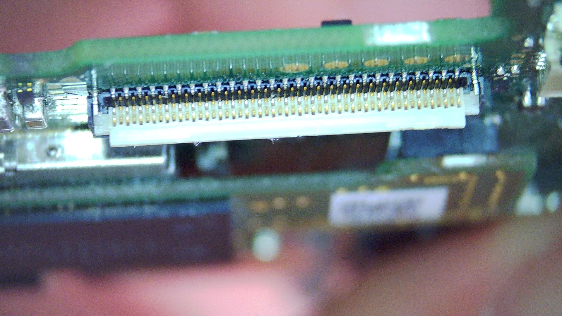
I’d also take a very close look inside the LCD connector for any bent pins too, though checking your rails as mentioned above will also rule this out too.
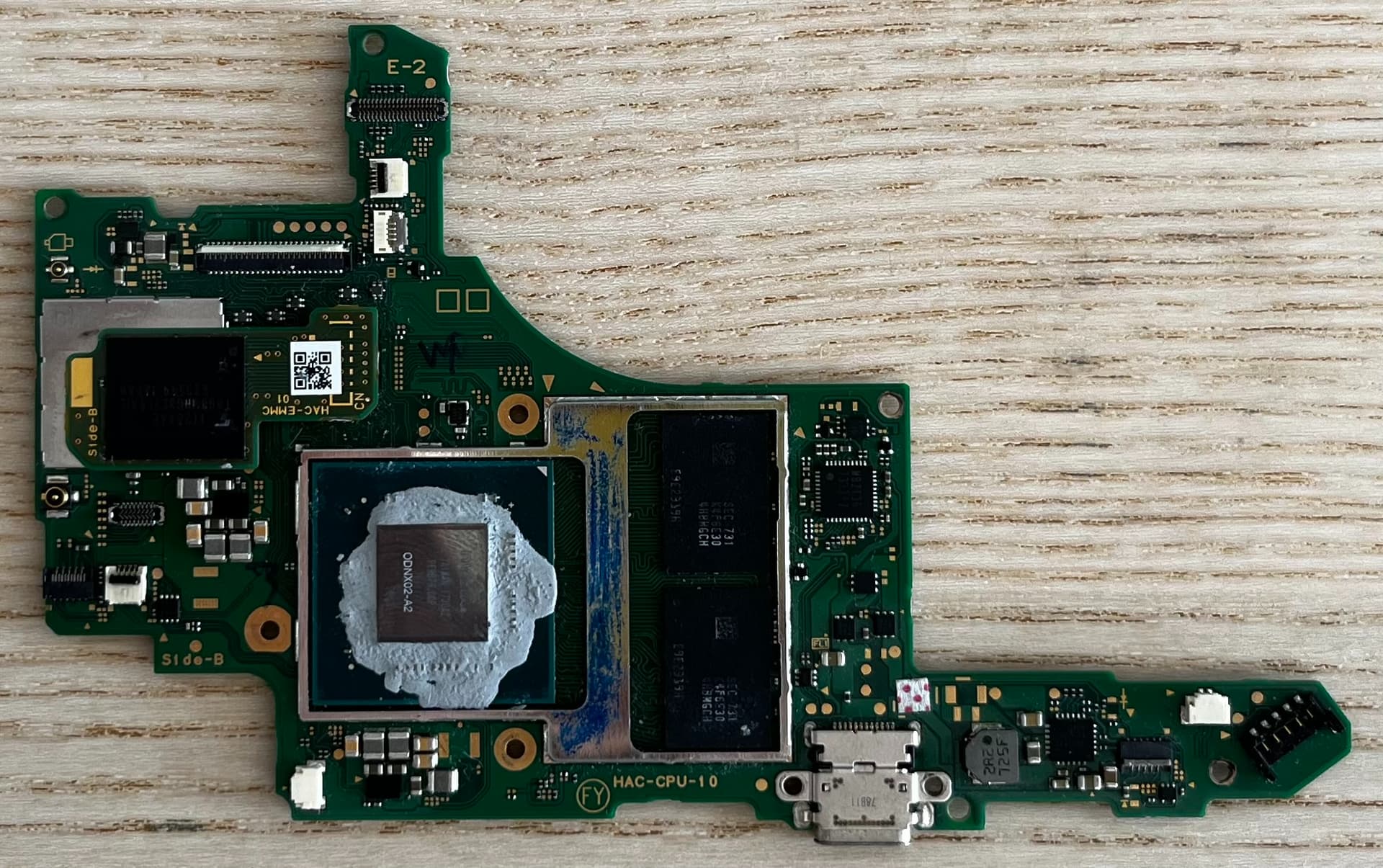
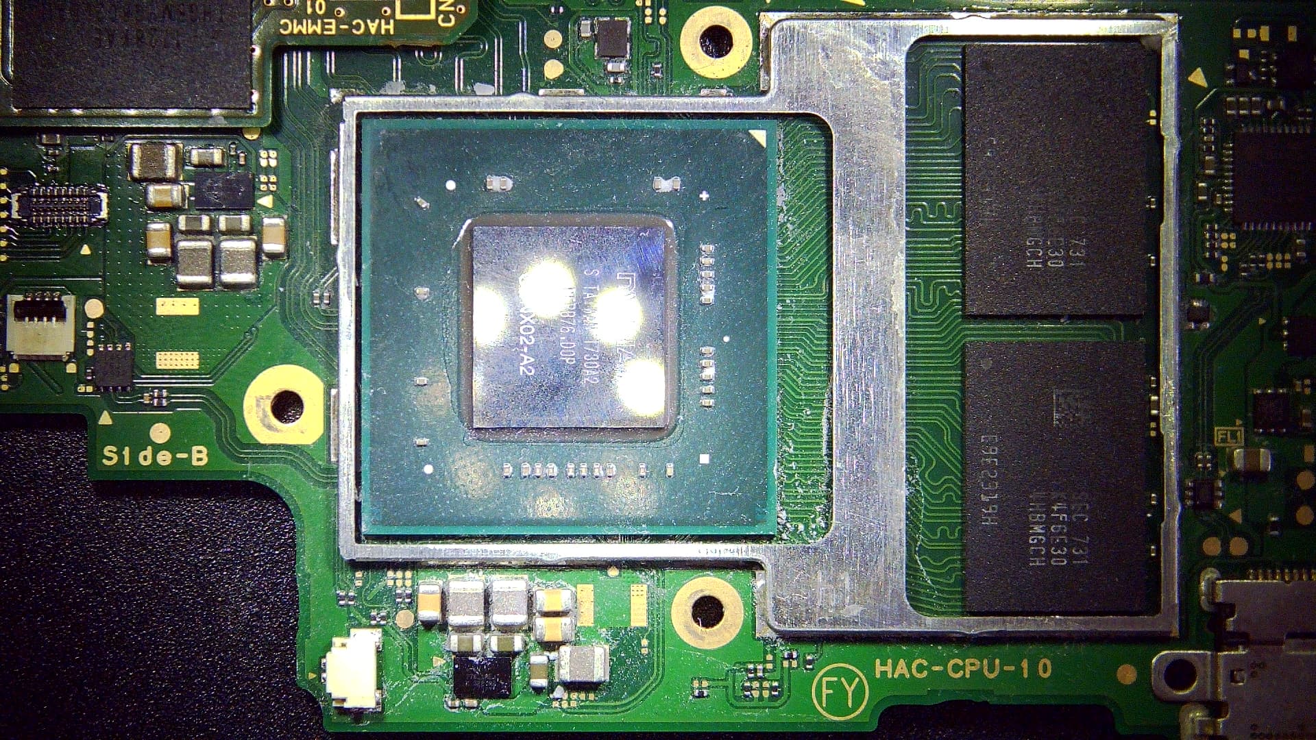
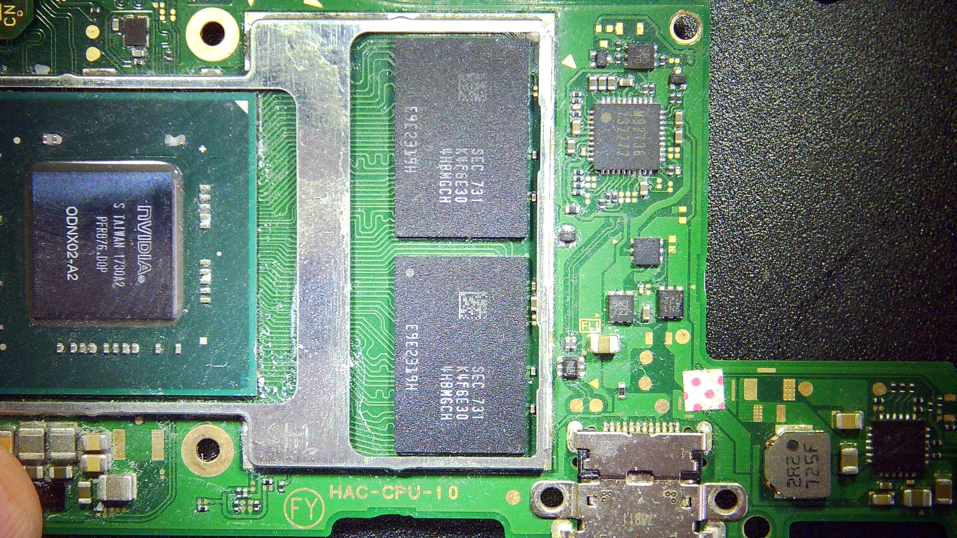
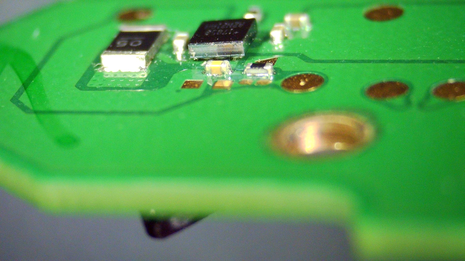
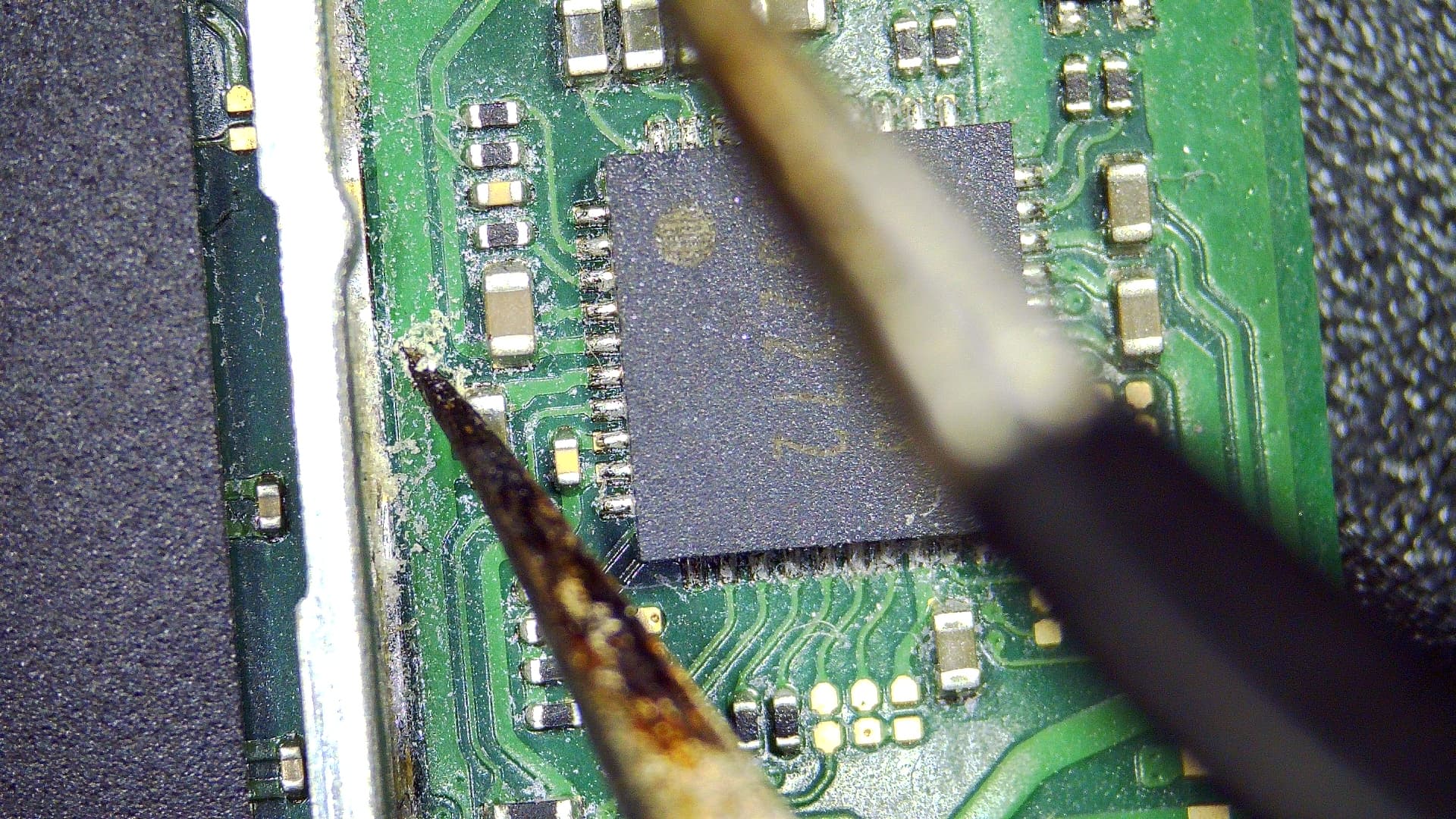
Based on the visuals it seems as though someone has attempted a reflow of the Ram, possibly the SoC too. Bit hard to tell from the image but it’s possible I can even see heat damage on the Ram IC’s. Can you provide better images of the Ram and SoC in better lighting so I can have a better look? and if you can clean up the paste too so I can get a decent look at the resin also does the SoC shield frame have a bend in it? as it kind of looks like it from the image but could just be a trick of the light.
Everything else looks fine, I see no indications that anything else has been reworked.
Techs usually do this to denote the BSOD, whether it is infact the SoC/SoC joints to board remains to be seen
Seems the previous tech had some idea of the potential causes.
Assuming your fuel gauge install is all good and nothing is shorted out (which is the only fuel gauge thing which could cause a no RCM situation, (open lines / bad chip would still allow it) Then best I can say is based on the prior symptoms and the indicators of reflow of ram/SoC is like your other board bad joints and it behaving intermittently as a result.
Got a few choices, you could hit the Ram IC’s with 80C hot air for a bit and see if the symptoms change (do you regain RCM state etc) just to narrow things down, then same deal with SoC. the warmth will cause expansion/contraction which could temp resolve the problem allowing you to narrow down the culprit.
second option is Ram reflow, though I think I’ve said before, I’m not a huge fan of randomly reflowing things (especially when fingers are pointing to the prior tech doing just this, and who knows what’s going on below) I’ll typically check the Ram rails and see if they are reading high, they typcially will in an open joint scenario (though you need good familiarity with your meter and the Ram manufacturer and also the board rev)
Third option, (even if the second option was successful I’d still do this step) I’d reball the Ram, might not be Ram at fault but might be worth doing and ruling out .
Then of course, SoC reball once again. and failing that, we’d conclude it’s either the board is toast or the SoC itself, maybe because of mangled SD pins (though this would typically be reflected on your primary raill resistance to ground measurments, 3V3PDR / 1V8PDR etc)
I might be onto something. The resistor above the fuel gauge is reading something different from all the boards I’ve seen (which is like… 7 haha).
In circuit measurements for a resistor doesn’t mean much if I remember Ohm’s law correctly.
But what if the tech who worked on that board changed the fuel gauge (poorly), sent that resistor flying, replaced it with another one with an incorrect value? Would this trigger the Alert pad on the chip? I don’t know what this Alert signal does, but it doesn’t sound like something good.
And that would explain why the board is behaving differently now that I’ve changed the chip. It is now actually triggering the alert thingy.
I’m going to test that tomorrow by pulling the resistor out and measuring it and potentially replace it. If this doesn’t work, I’ll try heating up as you’ve suggested. If it still doesn’t work, I’ll pull the chip out, just in case.
Generally speaking, you can measure resistors just fine in circuit in almost all cases, with the big caveat being other resistors being connected to one another such as in parallel configuration, for example 100k in parallel with another 100k and you will measure 50k across either in circuit, but in these less common cases it’s usually pretty obvious as the parallel resistor is usually very close by / side by side. Of course there are other exceptions to the measuring resistor in circuit rule too such as an IC which has a connection etc but in almost all these situations the effect is negligable.
Which resistor are we talking about here? there is the big 5 miliohm (if I remember corrctly) resistor which is serving as a current sense, which you should be able to measure fine in circuit and will read as a dead short + whatever your leads. As far as I remember this the only IC which uses the current sense is the fuel guage and given that the console should still be capable of an RCM state even without this IC we can assume even if that current sense was bad or open that you should still get RCM (afaik) .
Or are you talking about the smaller pullup resistor nearby with the connection to the alert pad of the fuel gauge? I haven’t looked at the fuel gauge datasheet for a long long time, but from my image of the board the resistor is apparently 100k and is pulling the alert line high to 1V8PDR, I’d guess (without looking at the datasheet) in the event of an issue the fuel gauge would pull the line low, or maybe the line has a connection to the SoC also as a single wire interface and SoC can act accordingly (sorry don’t remember off the top of my head) if it’s the latter case and this seemingly 100k resistor is wrong / measures wrong then I suppose it’s possible the console might not boot without it. If it’s the smaller resistor your talking about then just measure across it and see if it measures somewhere in the neaighborhood of 100k, if it does then it’s fine
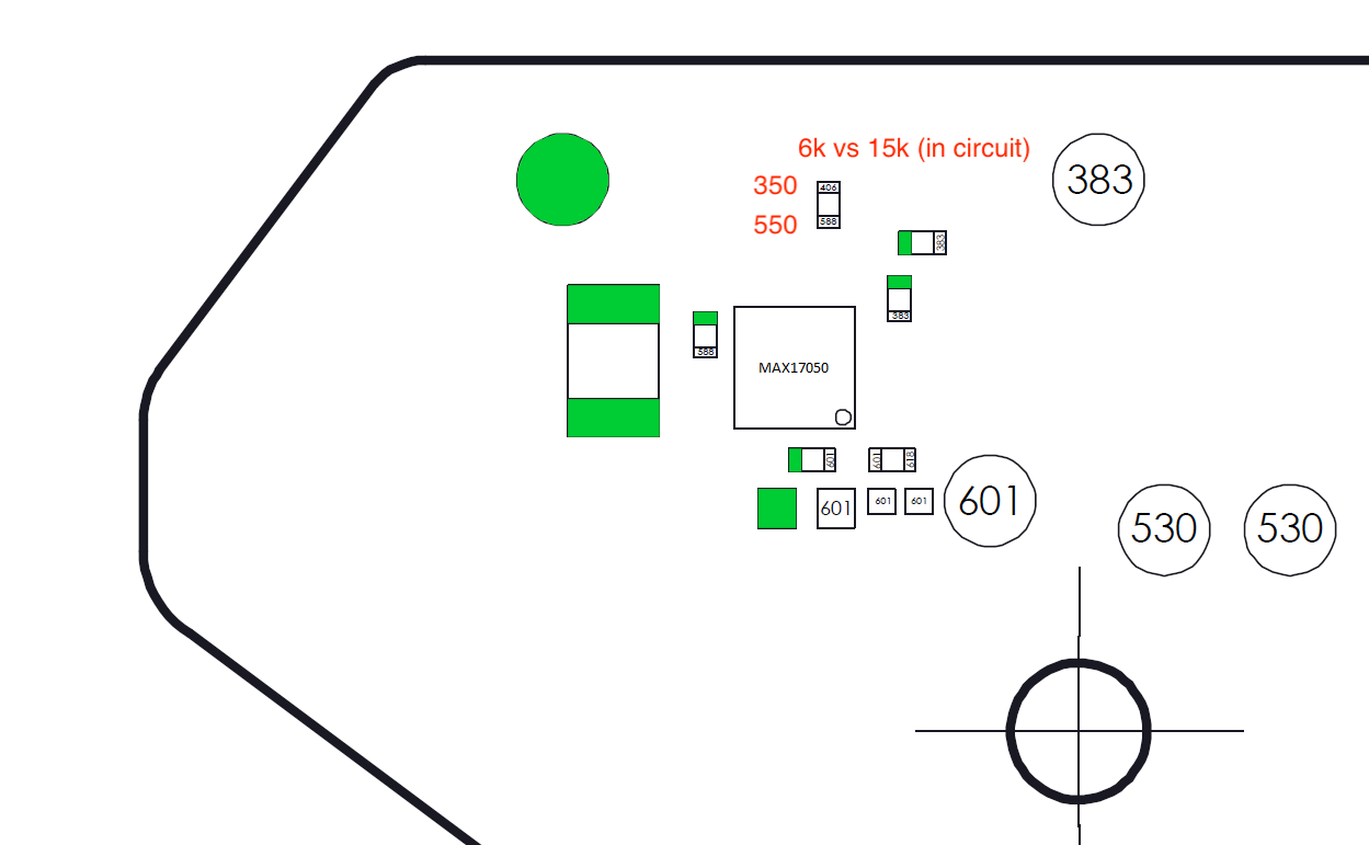
I’m talking about the resistor north of the fuel gauge, where i’ve added the readings in red.
It’s supposed to be a 100kOhm resistor. Because it’s in parallel with something else (not visible), it’s 15kOhm on my other boards and everywhere else on this forum. But here, it’s measuring 6kOhm.
Then can only be this resistor or one the other resistor/s in parallel on the other side which is at fault in that case. Whether this is the cause of the fault though still remains to be seen but one less problem when resolved
You can just swing them off one pad and compare them to another board in the same manner
I just checked: the resistor is indeed 100k, so it’s good. It is very hard to tell what’s in parallel with it. Following the tracks on the board scans leads to a lot of places all over the board, because that’s where the “alert” signal goes. So it could be anything in parallel. It’ll be different if it were a pull down resistor.
I went through the IC’s datasheet. They do mention a pullup resistor for the alert function, albeit being 200k and optional. It’s connected to a 5V regulator in the diagram. On the switch, I think it’s the one east of the IC and south of what seems to be a thermal resistance (which contributes to the alert function by the way).
I don’t know, it might be a rabbit hole.
I tried heating up the RAM ICs, then the SoC. No change in behaviour. Next up: removing the fuel gauge (just in case). Then RAM reball. I’ve never done that one, but it can’t be harder than reballing the SoC, can it?
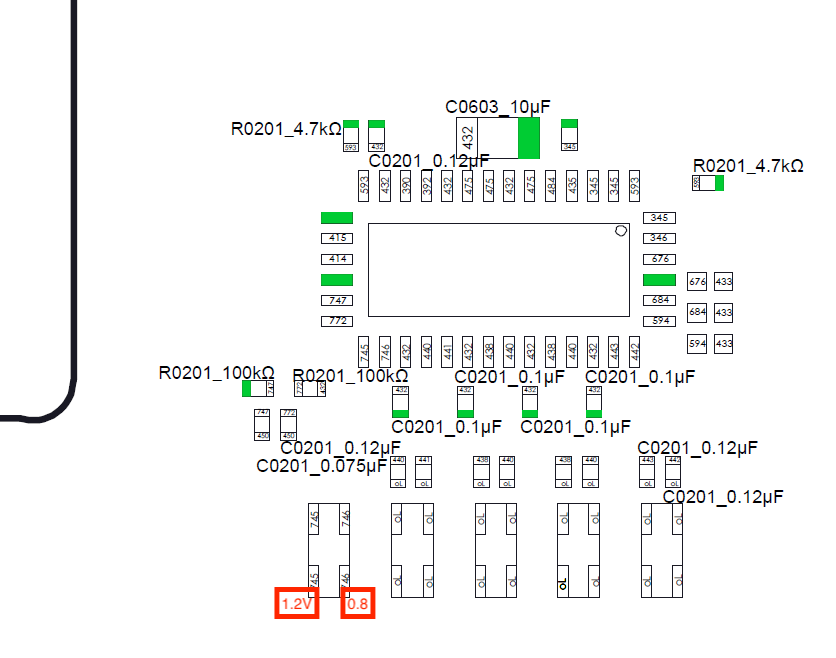
Unrelated I think: I believe P13 is bad, the readings in diode mode on some pins are too high (1.2V instead of 0.7V)
Board scans are ok, but often it’s quciker to do this yourself with an in person board, for future reference , grab some chunky multi strand fine wire, strip it back, and connect this to one end of your meter, solder a wire to the alert side of the risistor and connect that to the other end of your meter, put your meter in continuity and use the stripped back wire as a paintbrush (preferably on a board where the SoC is removed) and see where else the line comes up / what other component is connected.
In this particular case though, I can tell by the recently released Switch lite boardview, that this alert line in question only has a connection to the SoC and the fuel gauge, so in this case the only thing which could alter the reading your getting is the fuel gauge or the SoC (side note: evidently this is one of those rare cases where an IC is seriously affeccting the in circuit resistance reading which is somewhat uncommon ie. “low impedence”)
So, you’d probably wanna check resistance to ground on the alert line and compare that reading to a known good (multiple if you can) and see what you get, if the reading is significantly different on your patient even with the fuel gauge removed then that points back to the SoC being the culprit.
I just really wanna make sure though prior, you said your checked your primary rails earlier, how did 1V8PDR compare to your other boards?
Which lines?
It’s easy but this is another situation where i prefer using preformed balls over paste as with all the ram stencils I have the balls come out quite undersized when using solder paste which is not ideal.
Lastly, if everything point to the SoC, not sure it’s worth reballing the RAM (apart from practice). I could probably try to solder the SoC from the first BSOD switch.
Ah, damage to these lines is typically caused by bad USB scenario, this could be a variety of things, such as dodgy charger / cable / dock etc or mangled USB pins etc, sometimes it can kill the SoC. Sometimes it can cause trace/pad damage further up towards the P13 IC too.
might still be worth verifying the filter and PI3 but all fingers are now pointing squarely at the SoC being at fault at this point
Yeah probably not worth it, unless the tech screwed up the Ram reflow.
Yeah could do that worst case, just ensure none of the issues I mentioned above prior