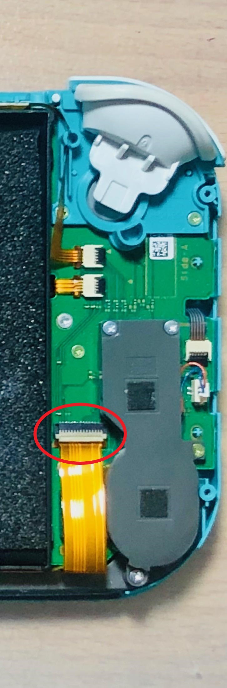
I have bought a water damaged nintendo switch lite, I have gotten it to boot up to the nintendo logo and then it goes black. I reflowed most of the IC afterward and noticed there was a pin on the fcp connector that was damaged from the water. I removed the fcp connector and place a jumper wire there. Bought a few replacment fcp connector but failed to install. I tried to apply hot air (400+ degree ) on the underside and it caused the fcp to warp upward. I then apply heat (400 degree) on a chisel tip, it kind of work but also kind of melted the fcp connector. I kind of screwed up the surroundings around the pad after applying solder many times  Any advice would be appreciated.
Hey
Not sure why it would have done this unless air and temp were too high.
Practice on a similar mass board to get a feel first and to prevent further damage. Once your confident, tin pads with leaded solder, flux, place connector and heat underside with minimum airflow
Also, you may have to add more mask to a few areas prior, else surface tension won’t be on your side
I bought low melt solder. I’ll try with that. What do you mean add more mask and surface tension ?
How do you usually “fluff” or tin the pads ? Does the solder iron tip touch the pads or just hover above it? What degree do you use after wicking away the solder ?
Thanks
Don’t use low melt solder here, it doesn’t have the current carrying capabilities of regular solder and is not neccessary for this job. Low melt should be reserved for aiding in solder removal only (particularly the cheap stuff)
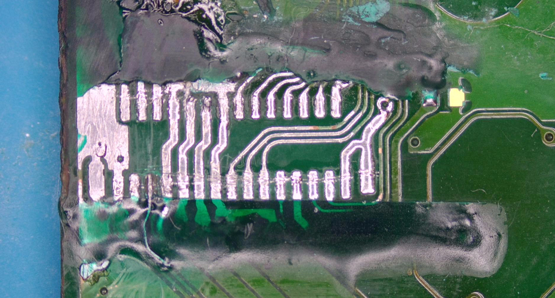
as the original solder mask is no longer present in the center and elsewhere, the solder will take the path of least resistance as will the pins on the connector during reflow, the solder will suck from the “original” pads and move inwards lifting the connector… if that makes sense, so, you want to use the solder mask in such a way that your recreating the original pattern and not giving the solder and in turn the replacement connector a way of escaping ![]()
I will use a JL02 or J02 style tip, using the heel of these tips, theyr’e very good at releasing the solder due to their rounded nature. I flux up the pads, and put a blob of quality leaded 63/37 solder (chip quick in my case) and linger on the pads for a while so the board can absorb the heat, i’ll then almost hover the tip over the pads, very nearly almost touching the pads with the tip but not quite.
The temp i typically use is 400/420C on my iron, though my tips are all temperature calibrated, prior to calibration there was almost 120C temp swing between tips at certain ranges, so watch out for that.
If your having difficulty getting the pads fluffle, you can set your hot air to about 200C and hover it in that area while using your iron.
You can also tin the pins on the connector prior which will help the connector in self alignment, heaviliy flux the connector pins, put a blob of solder on your irons tip, then hover the ball over the pins, not touching the pins or plastic directly with your iron, don’t linger here, in and out ![]()
2 Likes
I see, I was tempted to use low melt because I thought it would not burn up the plastic parts of the FPC connector. Good thing I have only bought one. The composition is Sn42 Bi58 Cu8 from
How thin can I do a solder mask to not bump up the FPC connector?
Wick as much solder off as possible. heat up the board a bit prior, will help the mask flow a bit.
If you find it’s too bumpy after curing, you can sand it back with >1000G sandpapet
1 Like