I have 2 PS4 originals and across both of then, suddenly the exact same issue at the same time. The console glows white instead of standard blue and the controller glows white (again, instead of dark blue) and the controllers won’t hold a connection with the console and will glitch and/or randomly turn off, even when usb plugged in.
I’ve tried everything. From switching hdmi cables, power cables or usb cables, even TVs and wall plugs, to resetting everything imaginable from individual controllers to resetting the system itself every way possible. I’ve watched every Youtube video and read every forum and nobody has this same issue.
It was all perfectly working fine until randomly one day. Please please please someone help me. If I take it in, it will gobble up any dollar I have or hope to have when I sell one or both of them.
Causes White Light:
HDMI port broken
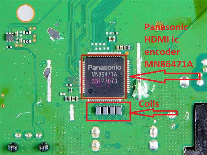
Panasonic HDMI ic encoder MN86471A burn
HDMI Control Chips Coil broken
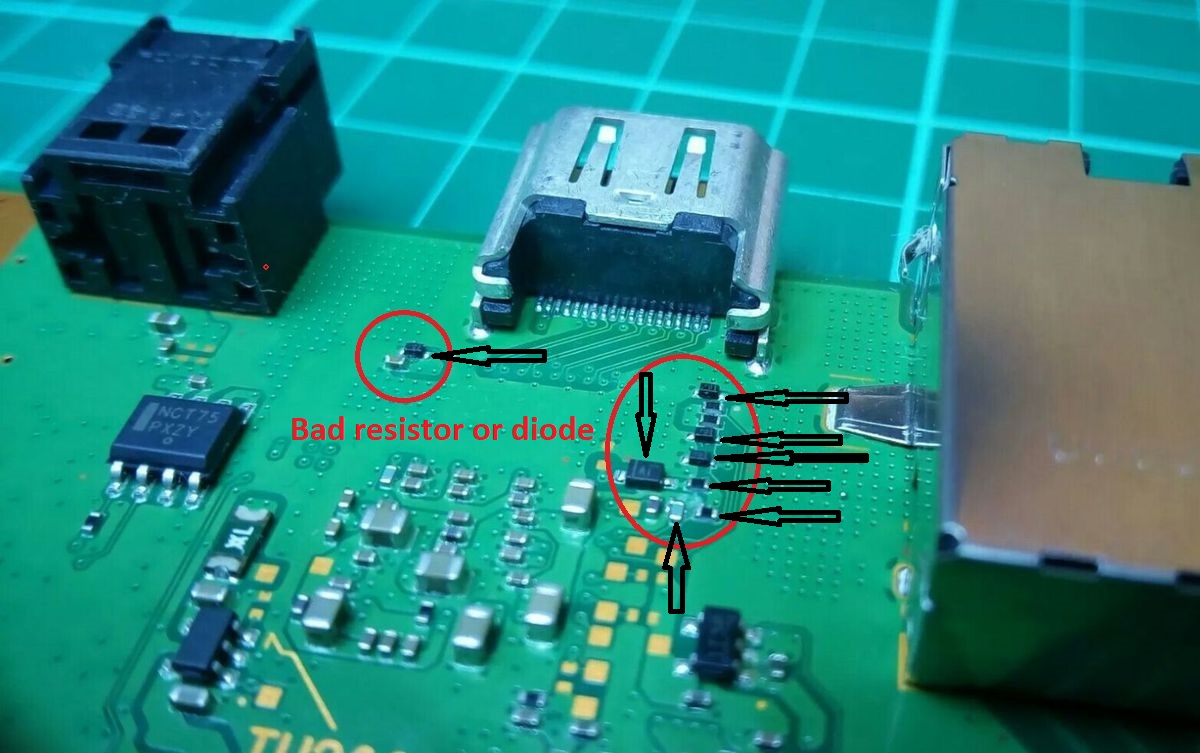
Bad resistor or diode
Usually the HDMI port has broken pins and then it will have to be changed. If the HDMI port is ok then the Panasonic HDMI ic encoder MN86471A is probably burnt and needs to be changed.
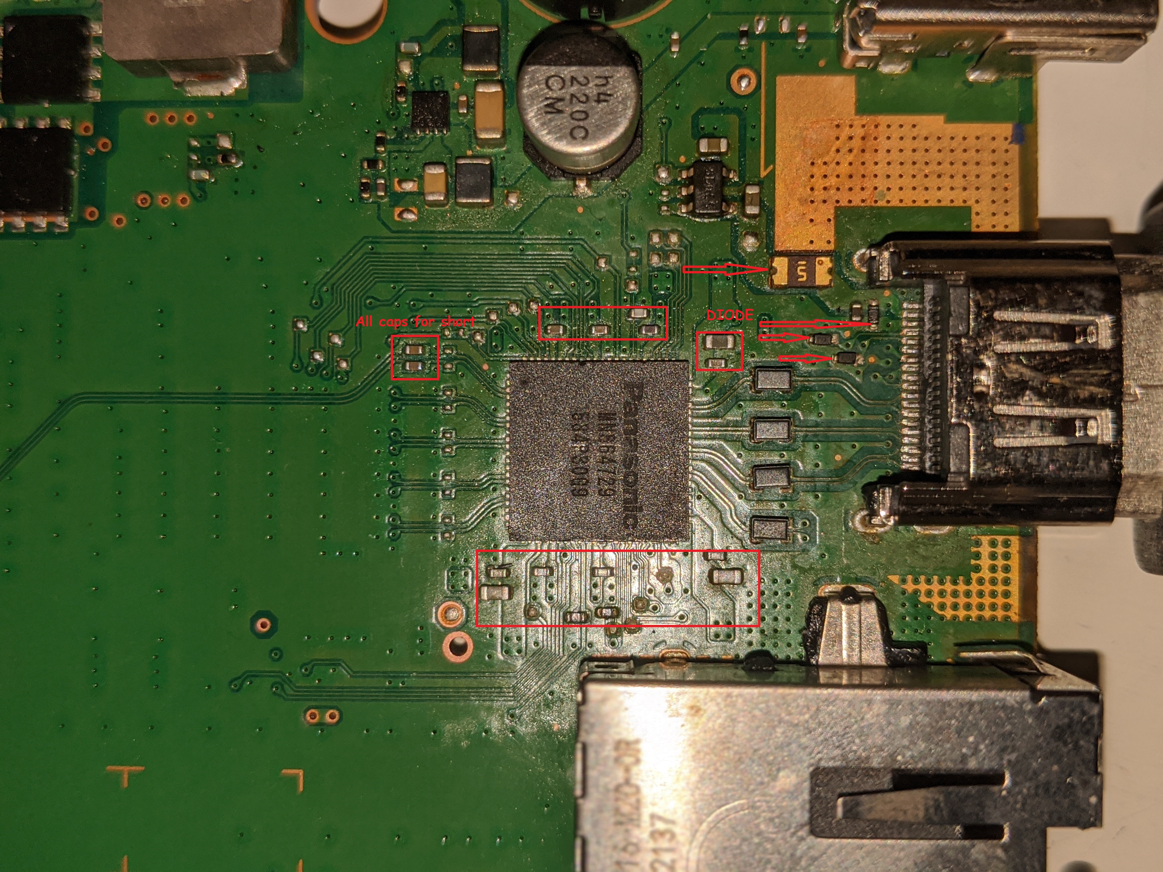
With a multimeter you have to measure the diodes and resistors near the HDMI port and see if they are short.
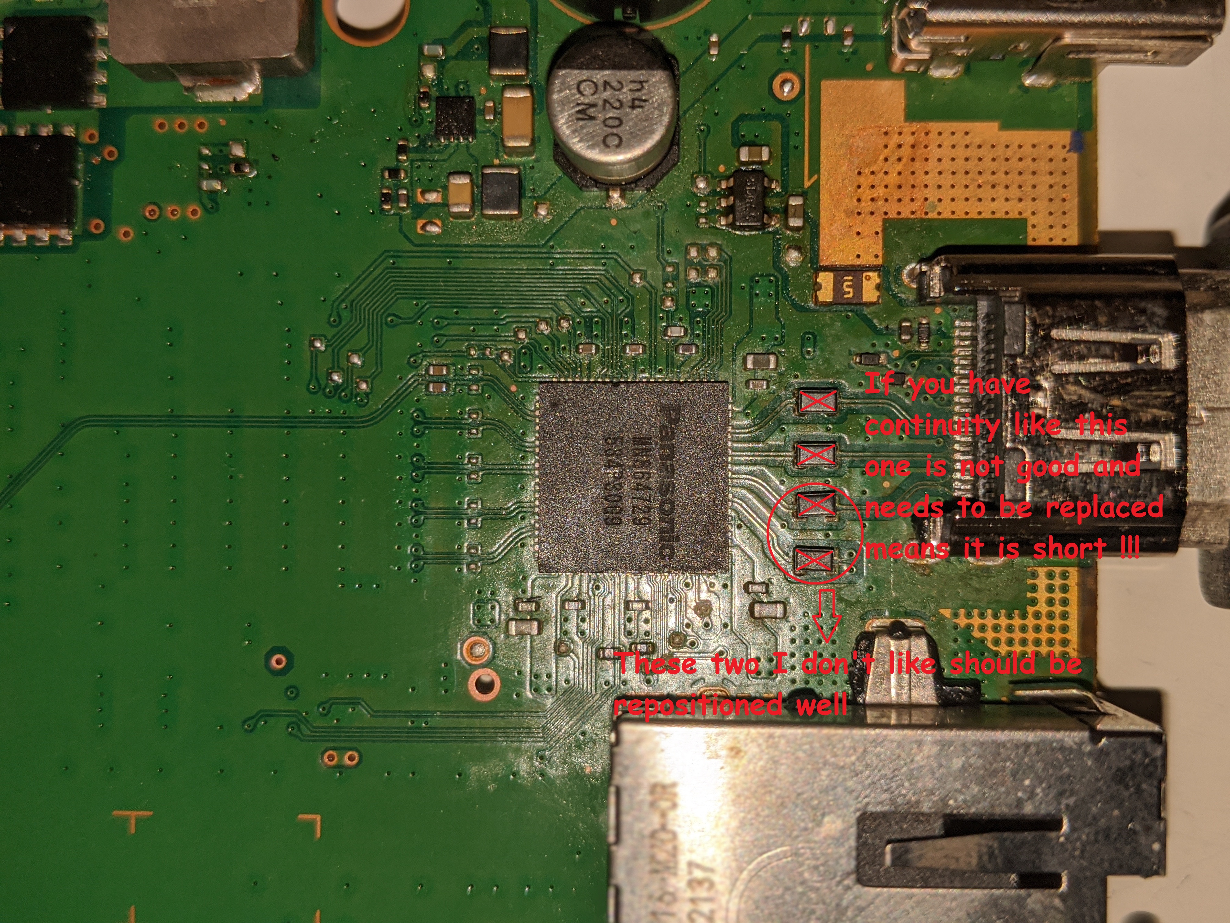
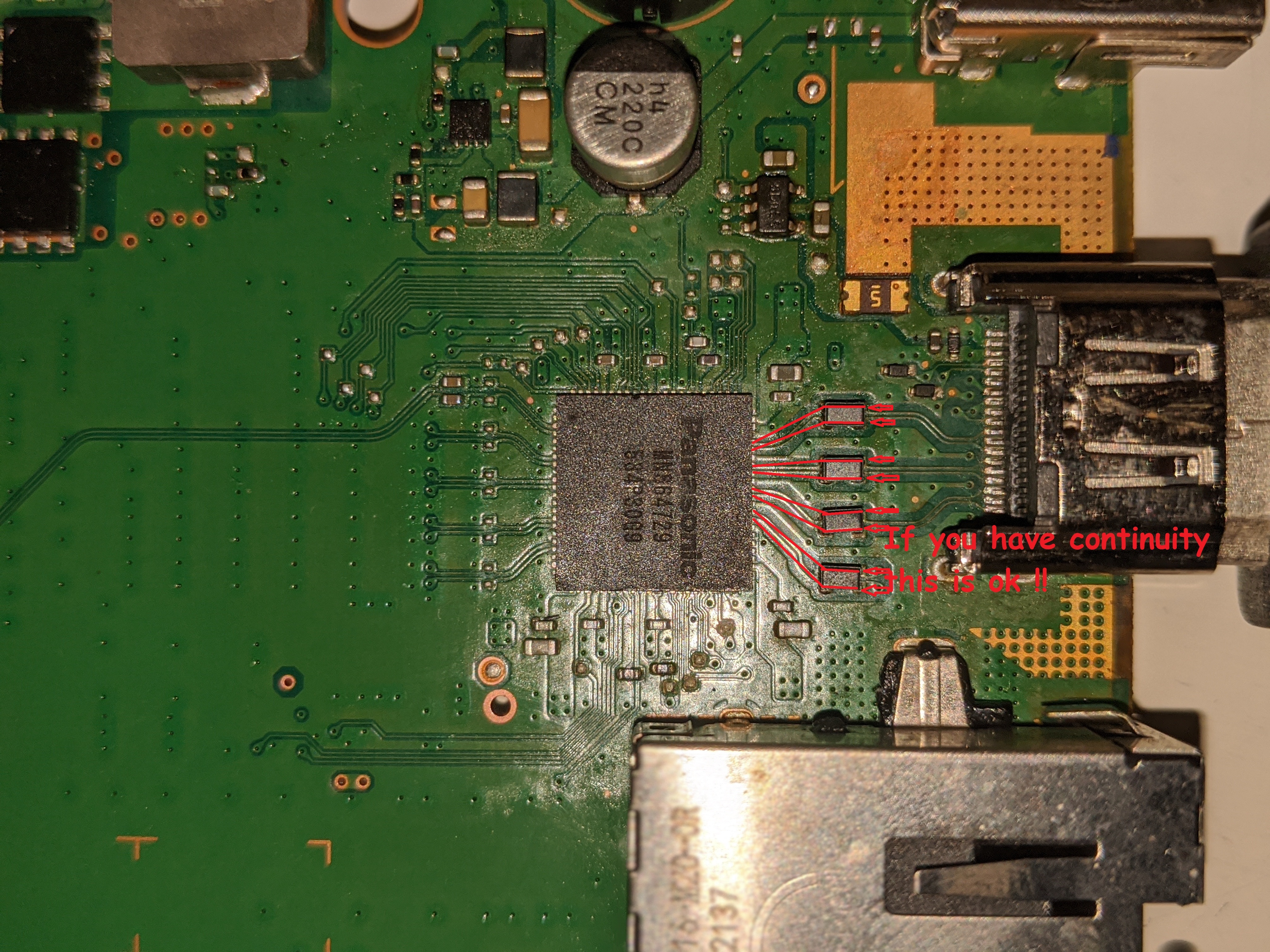
From the other side of the board you should measure the filters near the encoder if they are short and if they have continuity.
In many cases, the destruction of the ic encoder give short to diodes and resistors near the HDMI port.
Hi @FXDX,
I’m having a few rather frustrating issues with a PS4, but the model which uses the Panasonic MN864729 HDMI chip.
The person I bought it from said it was a faulty HDMI port. Once opened up, I realised the the HDMI port was sound, both inside and on the moterboard. I changed it anyway, just to rule things out. I took an HDMI chip from a broken board (BLOD) I had around, and replaced that, too. I’ve checked diodes and filters, and they all seem to be absolutely fine. I accidentally knocked a filter off, so I transplanted it from the donor board.
I’ve tested the board after replacing each component. Goes for the white light and absolutely nothing displays the monitor.
Would it be possible to ask you for the same type of image that you’ve uploaded above, but which is for the boards which use the Panasonic MN864729. I’m way too new to this and have absolutely no clue which resitors I should be checking in order to rule everything out.
Thanks!
Hi Bro. Put a picture with your PS4 board where you worked.
I’m afraid I cannot upload any images or add any urls to the post. Would there be any other way I can share them?
Thanks!
I think I might have found a possible cause. Lacking the ability to upload images, I’ll just try to describe as best as I can.
On the back side of the board, underneath the HDMI port, there are a few components. I can see a slightly larger diode aligned in parallel (geometrically) with a small capacitor (I presume it’s a cap based on its brownish color). That diode seems to be linked to a resistor. I’ve tried testing the resistor and it seems to be open.
I have a donor board, but weirdly enough, that one has no reading on that specific resistor either. Is that, by any chance, expected?
What model of PS4 do you have? That will tell the HDMI orientation. Sounds like you may have a 1215A or something close to that… This can be found on the bottom casing of the shell of the ps4. It would be next to a long white bar in greyish text.
Hi @Eldaros,
I believe it’s a 1216A. The board itself seems to be a SAC-001 board, if that helps.
Cheers!
Alright cool. Sadly my friend I am at the same sort of block with almost the exact same issue. What I can suggest is doing an HDMI pin out with a multimeter to see if all the connections check out. That can help the situation a tad bit. Andrew Paul has a great video for this:
//https://www.youtube.com/watch?v=fIgtTwM02GY&t=1123s//
(just get rid of the two double // at the beginning and end then copy and paste.  )
)
The pin out starts at 19:10. Hope this helps.
Mate, thank you very much, both for the pinout and for the “//” trick! I’ll definitely have a look at checking that all my pins are properly connected and seeing if everything is ok on that side.
To answer @FXDX’s request, here’s link to a set of images I of the board. It also contains an image of the area I was asking about in my previous post (i.e. the possibly shot resistor).
//https://drive.google.com/folderview?id=1FkvOxWPX08HZuDSvtrEgYJigoBp8Shro//
Thanks a lot guys!
Close attention to the continuity of the filters. Also check the diagonal not to be short. And the encircled diodes plus big resistance and caps.
I do not have a board like your version to measure that diode on the back of the board is ok.

Thank you so much for the guidelines!
I’ve checked all the 4 filters for shorts / continuity; they all seem ok. I will have a look at repositioning those. To my heavily untrained eye, they seem to be in decent contact, but you can never be too sure. I’ll double check the caps and resistors as well, too.
Regarding the HDMI chip: judging by the images I’ve shared, does that seem ok? As can easily be seen, I haven’t got too much experience with SMDs of any kind, let alone on a motherboard which is so good at dissipating heat.
Regarding the resistor on the back side, if someone could provide some input, that would be absolutely awesome. Unfortunately, I don’t have any working boards of this type, just earlier generations. The only other SAC-001 board I have is one I’ve heavily practiced on, so I don’t think it’s reliable either.
Also, another thing I can think of - I’ve desoldered the HDMI chip from one board and then resoldered it onto this board using roughly 380 °C and quite low air flow. I think it took me about 3-5 minutes to desolder it and about the same to put it back. Once on the board, I used a bit of isopropyl alcohol to remove excess flux (and I assume that helped with pulling out some heat from it, too). Should I be concerned that, in the process, I’ve also damaged this chip?
Again, thanks a lot guys, both for helping me out and for taking the time to go through these rather long posts of mine  . Cheers!
The HDMI encoder seems to be well placed. Now the fact that it was from the donor board may be a problem or not depending on whether it was functional.
380 degrees is a little bit for this chip especially if you took it from a donor board where you use a lead-free tin. I use 450 degrees with 20% air flow with a Quick 861DW station and not very close to the chip.
That’s relatively good news. The board I took it from was fine as far as HDMI is concerned. It had issues with the APU / RAM, I suspect. It used to randomly freeze and reboot even in safe mode whilst doing practically nothing. I did get it to boot once or twice normally and had full hd output. After that, could only get into safe mode even in the best of scenarios…
I’ve checked all diodes, resistors, caps and traces. Also reseated the filters and checked them again.
The only obvious issue still is the resistor on pin 13 I wrote about earlier. I’ve swapped it with one from a different board (SAB-001). I guess I might have used too much heat on it. When on the circuit, it seems that it’s still an open circuit. Before mounting it, it was reading somewhere close to 2k ohms.
If I were to use a bridge instead of resistor, should work enough to test the output?
Thanks!