Rather annoyingly i did this repair not that long ago but failed to document where everything went (at least on this joycon side)
The reasons for failure here ties back to a reply i made on another post, where somebody incorrectly installed a replacment USB causing this tail end to bow out - but also overwork of the BQ chip both in turn causing via damage (due to swelling)
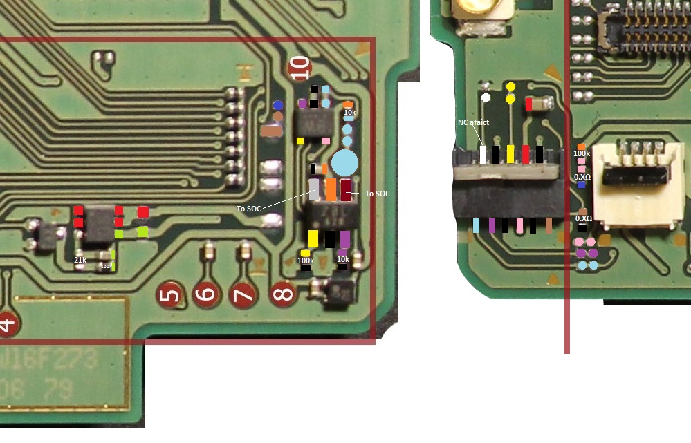
Symptoms were, failure to show the snap (animation) and i think failure to charge, but the controls seemed to function fine on the joycon, as a result of no continuity at certain spots, i had to snake three enameled wires in total (from memory) from the other side of the board up and around to the IC in the picture to resolve the issue as there was no other point to link to, and i believe also a resistor near the fuel guage.
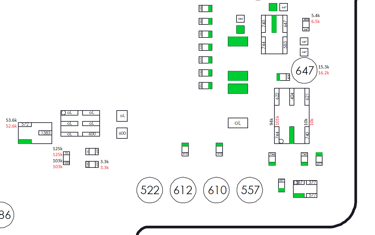
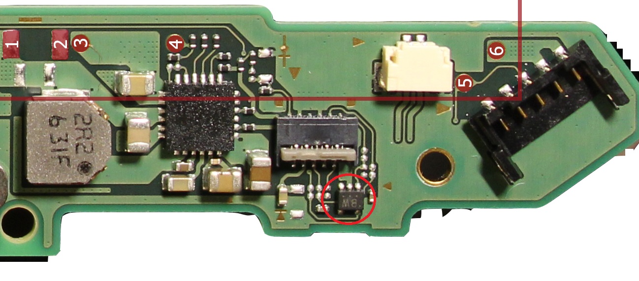
Assuming the joycon that is giving you the issues is the same side as in the attached pic? can you give resistance readings on the IC in both directions and tommorow i’ll provide a continuity map if needed.
If it’s the opposite side that’s giving issues, i will have remember how i solved that… was a long time ago i had the same issue on the otherside.
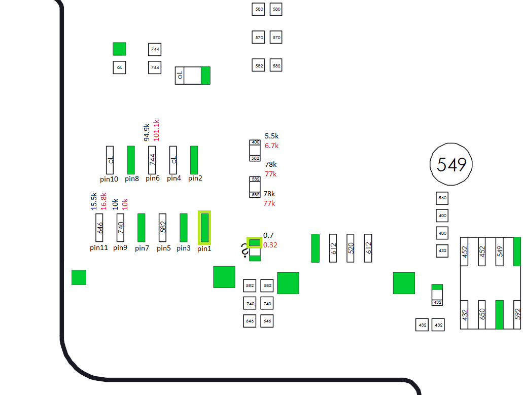
Worth noting, orange = 1V8 rail, a failure/bridge on any of the highlighted could potentially result in the bad resistance readings you measured before. Also might be worth removing the joycon connector to rule out corrosion/liquid jammed inside.
While it’s not as likely to suffer via damage this side, it’s feasable considering it’s close proximity to the SD connector.
Can you overlay the pad numbers on the connector in your diagram please?
Sorry, i haven’t yet documented the connector - as a result i have no clue where each pin/pad correlates or which order the numbers go in, i presume it’s a molex part… some manufacturers count sequentially some don’t
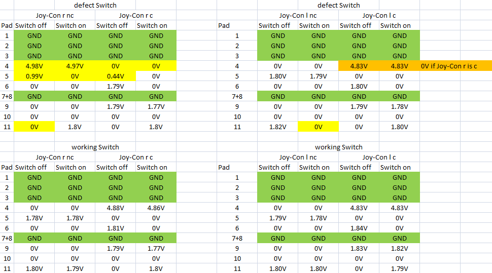
hmm your certainly getting some strange results according to your voltage measurments, particularly pin/pad 11.
tbh if it was me, I’d disengage my brain and windscreen wipe all IC’s off the board in that area and after measure resistance again on the 1v8 rail, if the values don’t return to normal (or atleast increase) then none of them are the problem.
Then you could try (at your own risk) cutting/isolating the trace at pin 5 and ensure it’s 0V or 0L resistance (both ways) and then pulling pin 5 high directly to the 1v8 rail via a 20k resistor.
Again though, i have not yet documented these joycon connectors or checked them on my oscilloscope and have no clue what pin 5 is normally aside from the voltages referenced in your graph
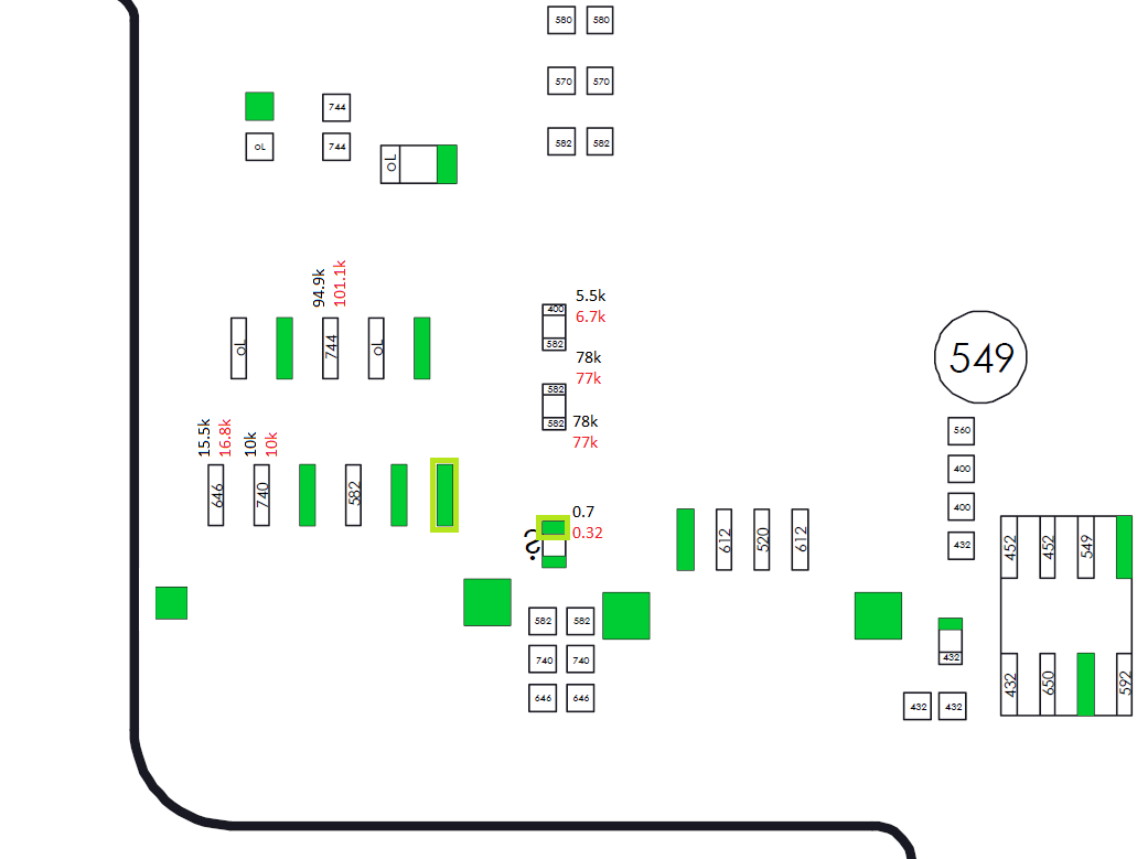
It would seem on a working switch and this is just based on me looking at the pictures and your voltage diagram and not doing any tests myself,
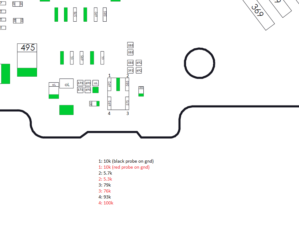
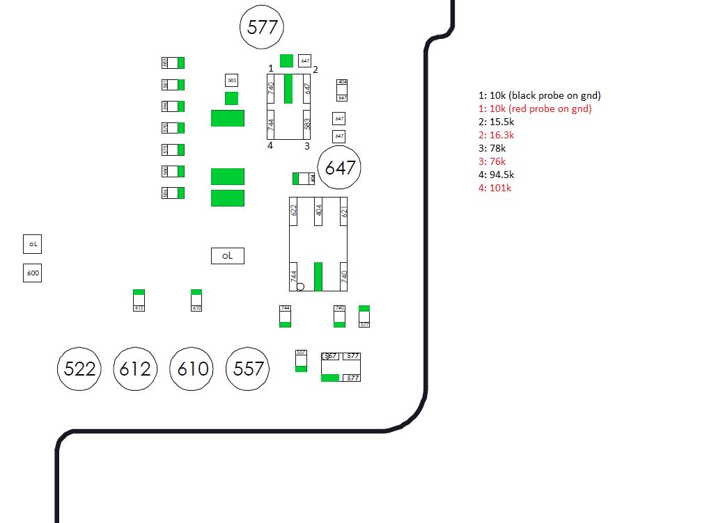
that the 3-pin transistor is signaled to turn on the fet which then in turn passes the approx 5V to joycon pin/pad 4, I’d guess pin/pad 5 is normally high (1v8) and when connected to the joy con is pulled low to ground which causes the signal on the transistor.
In your case it would appear the transistor is always telling the fet to turn on, so likely a problem prior to it, would be curious to know what the voltages are on the transistor and also without the transistor populated.
Also as pin/pad 5 appears to be getting dragged down by something i’m unsure at this moment if the detection would work if my assumption about the line being normally high is correct and the trigger voltage being >= 1.2V (guess) unsure if it’s the SOC interpreting the line here or the joycons onboard micro… or both.
Will do more tests on this at some point, but all of the above is guesswork with absolutely know tests or detailed measurements by myself…take em with a pinch of salt.
yeah would be helpful, maybe when your back we can start a public git or similar and add all the info so far, a boardview is 9/10 of the way there for a usable schematic and with access to more easily accessible datasheets on mariko hardware with pretty much 99% the same circuit functionality it would finish off the other 1/10th. The reason i gave up on it was because fusion had just implemented eagle functionality in it’s program and i couldn’t import what i’d already done after an update without re-doing a lot of what was done, out of frustration i gave up on it… was a buggy mess at that time and i didn’t get that far tbh anyway.
Alright man, same to you, merry christmas and a good new year!
I gave it a new try and replaced the m92t36 again and checked every thing. I first tested a charger with 5V and everything was fine. After pluging the original Nintendo charger the 2101-0001 error appeared again and the short on pin 38 at m92t36 is back. Maybe I m wrong but I guess the 17V are somehow frying every time the m92t36.
Ok I have this same problem on a switch. To the point now that I’m leaving the m92t36 off until I can find the solution. I’ve killed 5 chips and I don’t want to kill any more chips as its costing me money. Look forward to anyone’s bright ideas. I’m going to test everything I can on the board to try and find out what’s at fault. Did anyone have links to images with reading’s they could post up?
The above posts should have all img you need.
I gave up onto that typical board long ago and I can only add up something about 2101-0001 code is that pin5 goes down to 2.6v ish with the bad M92t36 with 5v 0.02amp charger plug-in(does not ask for 15v)


 classic