ANOTHER Switch Lite won't turn on topic... Though my symptoms seem different than usual?

Hello!

I know this question has been asked countless times. I’ve scoured the web, read a bunch of Reddit posts, a bunch of posts on here, watched countless Youtube videos of others diagnosing / repairing their Switch Lites. But, I’m coming up short in my situation, and am hoping that my diagnostic findings will helps someone to pinpoint a better idea of what’s wrong with it!

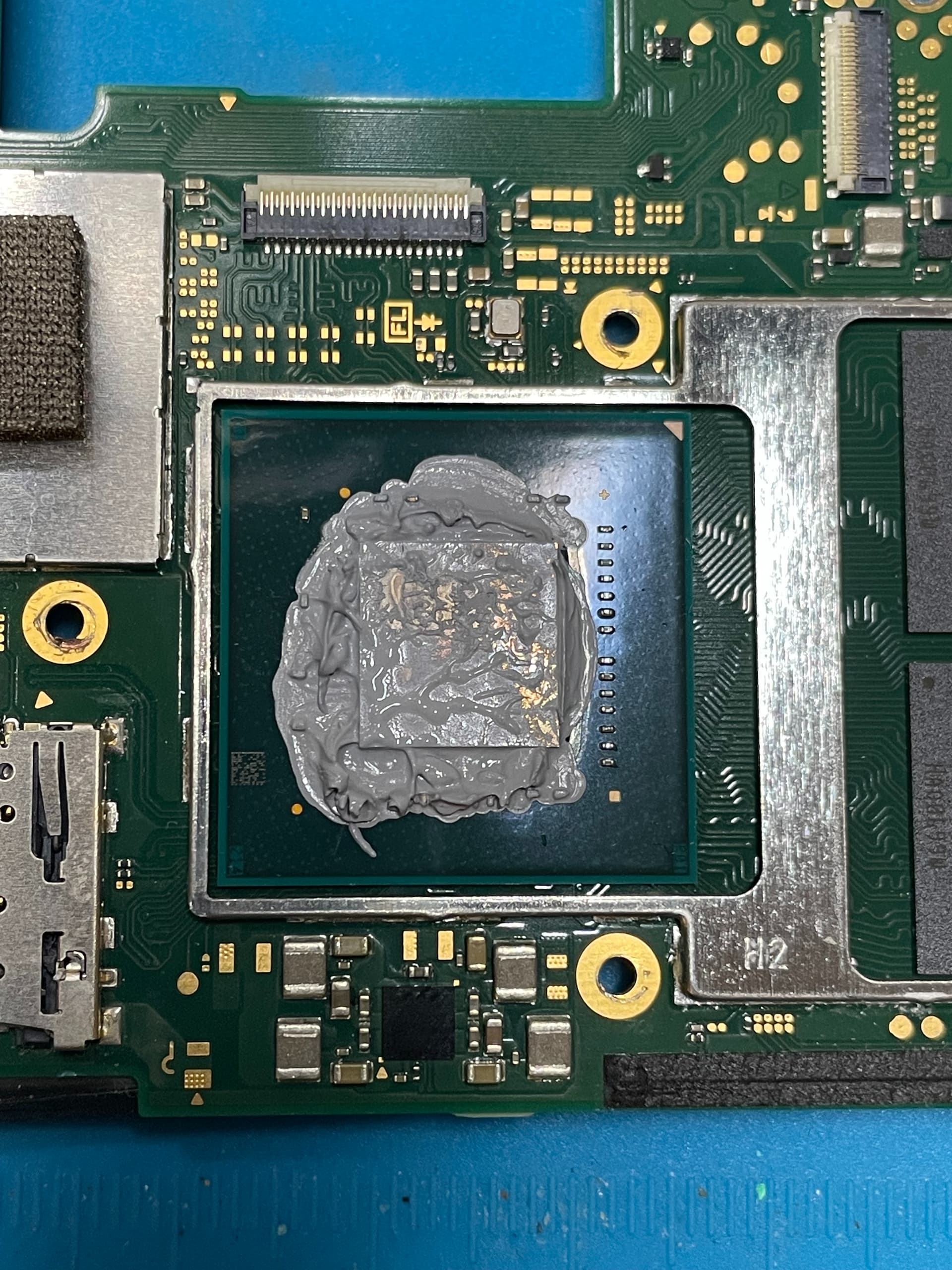
I purchased the Switch Lite off of eBay, which got delivered a few days ago. So I don’t know the previous situation that got it in this state. It is pretty beat up around the outside, and there is a screw missing from the top. However, after opening it, nothing seemed out of place or disassembled, and the foam was still intact over the exhaust fan. So I don’t think it’s been worked on previously.

A quick rundown of what I’ve tested:

  • Tested for shorts around the M92T36 IC. No shorts.
  • Tested for shorts around the BQ IC. Also, no shorts.
  • Visual inspection of the USB-C port. Looks perfect, with no pins out of place.
  • Plugged in a 15V USB-C plug with an ammeter to check. Constant draw of 15V, and ~0.46 amps. This does charge the battery however. And once the battery is full (4.2V), the current draw decreases to ~0.2 amps. Note however, that the ammeter never shows that the Switch actually boots up (ex., it never resets during any boot sequence).
  • Removed the board out of the system and unplugged the battery. With JUST the board, plugged in a 15V source and checked with the ammeter. This time, it sits at around 0.02 to 0.03 amps and idles here. As before, no reset to 0 amps and nothing to signify it tries to boot.
  • Repeated the same procedure as the previous two, using a USB-A → USB-C cable at a 5V charge. Same exact current (0.46 amps with a battery, 0.02 amps without).

Now, with all that said, here is where it gets a bit interesting. HOPEFULLY this bit will help pinpoint what may be wrong?

If I plug a 15V source in without a battery, the system will draw the 0.02 to 0.03 amps at 15V for about 22 seconds. Then at that time it drops down to 5V instead, and remains at the same current draw.

Furthermore, I came across a comment here by @jkyoho.
(I guess I can’t post links, so it’s in the post titled “Switch Lite Won’t Charge…Help?”)

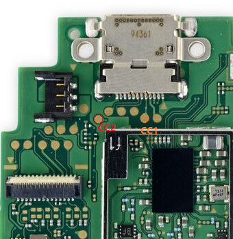
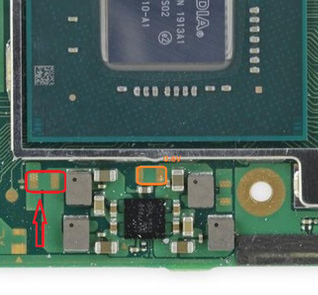
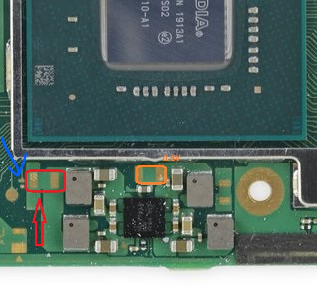
In it, he lists 3 test points to verify against. The user who made the original post, provided their results:

A → 5.24V
B → 0.04V
C → No Reading

I tested those 3 points on my own, and got the same results. HOWEVER, I noticed something. I got those results ONLY if I plugged in a 15V source, and then waited until it dropped down to 5V. If I tested those points immediately while it was still charging at 15V, I got the following:

A → 15V
B → 15V
C → 4.24V

Even more weird, if I instead plug in a 5V USB power source, I get:

A → 5V
B → 5V
C → 4.24V

So, I have voltage at all 3 of those points, UNLESS I charge at 15V, and wait about 25 seconds for it to drop down to only 5V. When that happens, I lose voltage at B and C test points.

So, it sounds to me like there’s a voltage negotiation problem somewhere. Whether that’s the M92 or BQ chip, or something else, is so far outside my realm of knowledge, I have no idea. I know at this point I can start swapping chips and see what happens. The only problem is I don’t have a hot air station, nor do I have replacement of either chip. I can order them to try, but I was hoping to have a clearer idea of what’s wrong, before blindly buying tools and swapping out chips.

Has anyone else seen that voltage fluctuation like that before? I’m just confused how it seems I have voltage at 15V initially, and I have it at 5V initially, but I lose it if I start at 15V and it drops down to 5V after ~22 seconds. And I have no shorts.

Hopefully I’ve done enough due diligence at this point that it helps to have a better idea of what’s wrong. Thanks for any advice you may have!

you mean this post?

Measure your cc1 and cc2 diode reading
image
and do you see your 15v source boost to 15v from 5v or your sniffed it to 15v?

Yep, that post! I was testing the 3 points (A, B, C) that you mentioned in your response in that post.

For CC1 and CC2, I got similar results.

CC1: 1.128V, 0.493V (other direction)
CC2: 1.120V, 0.491V (other direction)

and do you see your 15v source boost to 15v from 5v or your sniffed it to 15v?

I sniffed it at 15v. I have a battery bank that outputs up to 20V over USB-C. When I first plug it in through my ammeter, it shows 15V, which I verified with a multimeter. Then it drops to 5V about 20-25s later (both on the ammeter and confirmed with a multimeter).

Thanks!

ok, so likely the battery bank has PD protocol supported.
I don’t recall any scenario where 15v drops back to 5v even battery fully charged or unplugged.
What voltage/boot stage do you see with charged battery when trying to turn on device?(MAX77820 area voltages and MAX77602H area)

You know, I didn’t even think about the fact that the battery bank might be causing the voltage changes. I grabbed a USB-C wall charger and tried it instead, and it stuck at 15V indefinitely, even without a battery connected! Now I feel foolish. So it must’ve been the battery bank that was auto-dropping to a lower voltage after awhile. I suspect that was due to the low current draw of the connected device (the switch, in this case). Now with a wall charger, it’s a continuous 15V output. I also confirmed after more than 30 seconds (when it usually was dropping to 5V with the power bank), that A, B, and C test points from before still all had the correct voltages.

With a charged battery, I poked around the MAX77602H area on the back of the board. I got 1.1V and 0.85V across a few different caps / test points. With the MAX77812 chip on the front of the board, I got 0.6V across a few test points / caps, but nothing beyond that. Does that seem off?

Thanks again for your help!


Do you have any voltage on red test point? If you only have 0.6 or 0.8v on orange or right side, that is stage1 boot. Red circled test point is stage2 gpu voltage.

that pretty much states your charging circuit is good

On the orange test points, I have 0.6V. On the red test points, I have 0V. Nothing at all. :frowning:

I did verify that on the teeny tiny point just to the left of the red test point (blue arrow), I have 1.54V. I don’t know if that means anything, but I did just want to point it out while I was poking in that area.

Seems to me to be a classic case of 0.4 / 0.5A braindead which could literally be anything unfortunately.

Take a very close look at the backlight IC and connecter etc for damage which is a common issue on Lites and if not that then as mentioned could be anything, M92, EMMC, Fuel gauge etc etc etc etc etc :frowning: search the forum for “primary rails” in the Switch category and find a few topics beteen me and other users and how to check them in order to narrow down a potential culprit. Unless of course @jkyoho can think of anything.

Curious if any sign of work done before around the test point between cpu and LCD connector. Can you take a picture?

Thanks! Yeah, that’s what it seems like. I’m at the “etc, etc, etc.” stage, lol. I did buy another broken Switch Lite, that should come in the mail on Monday. I’ll probably spend a good long time testing out voltages between the two, and seeing if that helps narrow down what may be wrong. Otherwise I’ll just write it up as a loss. At least I have a (hopefully) good screen, membranes, daughter board, etc, out of it!.

@jkyoho,

Sure! Here’s a picture of the area I took. I just removed the shield covering the CPU, so that’s my doing. The rest of it seems immaculate and untouched.

Curious though, when I took it apart, there were two screws on the board on the left side (one going through the small tab on the large metal shield, and the other securing the speaker through the board to the chassis). Both of those wouldn’t come out. Eventually when I took everything else off, the board came off with those attached to some posts on the chassis that had been broken off. So I suspect it was dropped on that corner, which caused those two posts to snap. I wonder if that dislodged a solder ball under a BGA chip somewhere. I couldn’t find anything that looked at of place, but I suppose I’m at the point where I just need to keep inspecting!