I am new to this forum but have seen a lot of helpful posts that seem similar to my scenario. Sadly I am not the very experienced in PCB design or reading PCB layouts and I have questions for many of the answers. Any help is greatly appreciated.
Request: Find a way to get my switch to charge it’s battery again if possible.
Story: This is a personal switch that I installed a trinket on to boot to Android. Ended up removing the trinket and now the switch won’t charge. The battery has since died and it won’t turn on anymore (I presume because battery is dead). Prior to the battery dying I could connect up a USB C charger and it would either recognize it and not charge or charge it slower than it drained. Before it died the USB C charger stopped registering.
Things Done:
Checked fuse near USB C port and it had continuity
Things Noticed:
Battery voltage only returns noise (0.3 mV) when using multimeter in DC mode to read either of the reds to the black. I am unsure why no value is being received unless battery has a chip on it that needs a the gray wire to be high or something. To take this value I removed the 2 wires from the battery connector to ensure I had a good connection to the multimeter. I can upload pictures of me testing the battery if that would be helpful.
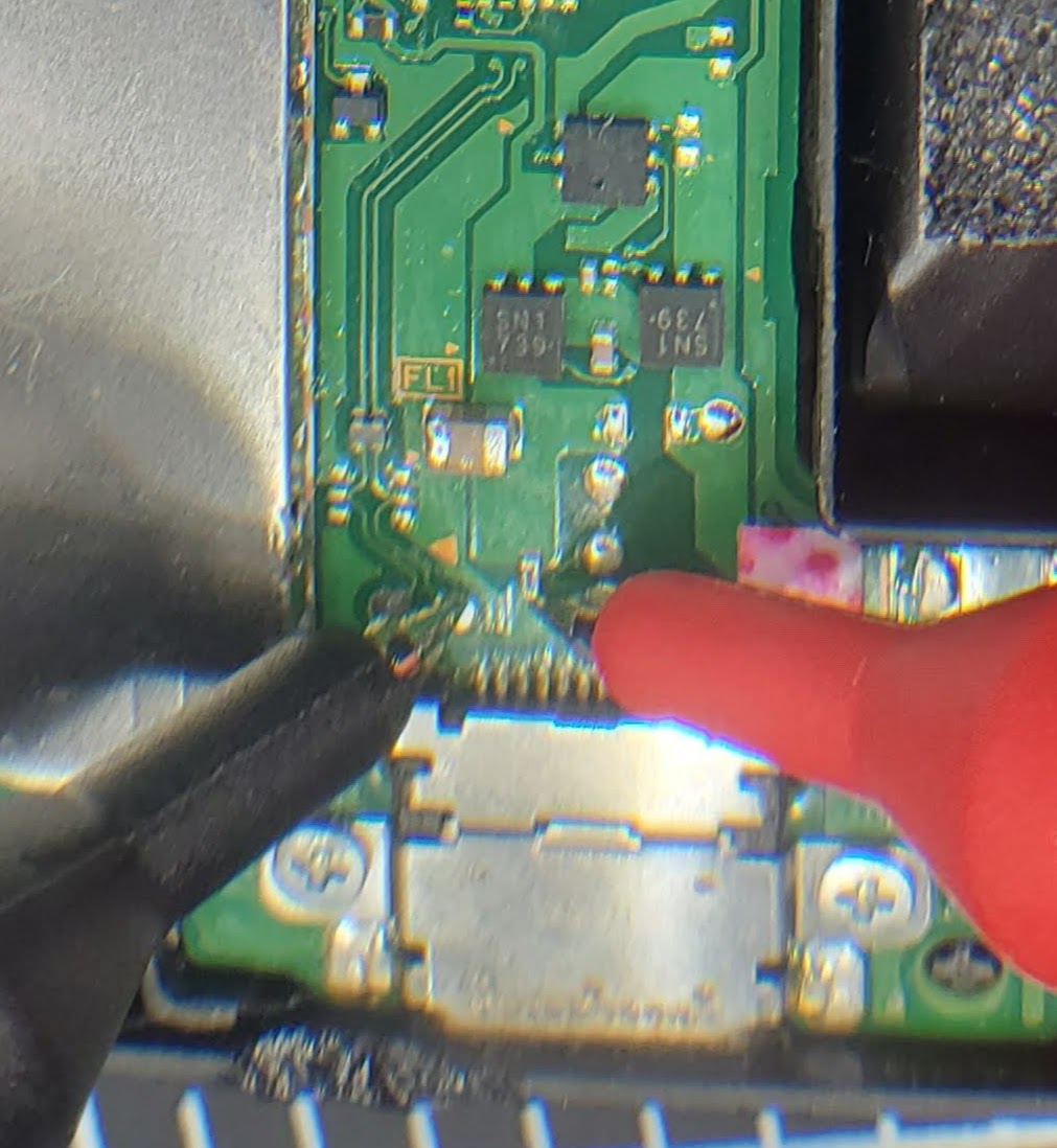
The capacitor to the left of the charge control chip is missing its cap. Is there a way to test if the capacitor is still connected properly? I will upload pictures of this tonight.
Things I’m comfortable with:
Using multimeter
Getting high quality macro shots of the board (to show where I believe problem areas are). I will upload some shots of the spots that I worry about once I am home later tonight.
Replacing battery or connectors
Soldering if necessary (I only have a cheap Chinese knock off soldering iron that has trouble having solder stick even after tinning multiple times).
Do you know if there is a way to test if the capacitor mentioned above is still properly connected? If it is, is there a way to test the charge control chip (M92T36 and BQ24193) to see if they still work? I’m open to any suggestions people have. For the most part I have given up hope on this switch and don’t foresee it coming back. Serial number starts with XAW10 if that is pertinent.
Hi, a lot of your questions are answered on other threads, such as checking outputs of the various chips M92 + BQ. I would check out the threads and read previous suggestions in case someone doesnt have the time to reply to the same type of question. Also you can check the images uploaded for correct connection of caps just be sure to check against same board version because some v2 components dont have things where the v1 does or at all.
Have you checked for any shorts on the IC’s with the multimeter? The trinket installed involved soldering? if so have you checked that area for damage or shorts?
I have seen on other threads people describing testing the path up to the M92T36 chip (Post nintendo-switch-0-amps-and-no-display/3422) and I have confirmed power gets up to that pin with continuity testing on with my multimeter, but don’t know how to test the IC itself. Do you know a good post I may have missed that has that information? I believe the issue is either related to the capacitor or the M92T36 chip but wanted to check before replacing either of them.
For testing the capacitor, I have seen people say to check if only one side of the capacitor is connected to ground (if both are it is bad), but I do not know where the proper ground to test is (if there are multiple ground/power planes on the switch) and the post I saw didn’t mention which/where a ground point to test is. I will look further for posts related to this.
Another thing that confused me was I saw the fuse right above the USB C port should have continuity across it (to show it is not blown), but one of the responses said they knew something was wrong when there was continuity and that removing the fuse and bridging the pads seemed to work (Post nintendo-switch-not-charging-no-charge-icon/3332). This seems counter-intuitive, so wanted to start a conversation if that was correct or if continuity means to leave the fuse alone (want to minimize soldering/desoldering if possible).
I read Post not-charging-but-everything-else-works-fine/3233/5 and it seemed pertinent, but I don’t know what cc lines are and want to make sure I test things properly to not burn anything out (some people say tests with USB C plugged in, which I would like to check things such as risks of shorting with surrounding pins or if battery should be disconnected while testing with USB C plugged in). That post also says to test the BQ status pin which I have found pinouts for, but don’t know what to test it connected up to (ground, a separate pin, etc.).
As a side note, I tried to post a response with links to the 3 main related questions I saw and questions I had on them, but it wouldn’t allow me to post links. Also seems I can’t post images so I can’t show the spots I think problems might be.
I can just try to clean the board up and avoid those sections and focus on the other posts. Do you know if people usually respond to old posts? I was initially only getting the first ~20 posts until I switched to my PC as now older ones are loading. I will check older posts and update this post once I have more info.
You can use the usb c port as the ground. Put your multimeter in continuity mode ( it should look like a little speaker symbol) and then prob against the sides of the caps. only 1 should beep. you should start with that as itll give you some clues to which chip may be bad right off the bat.
I had a Switch with a drained battery while using custom firmware. It wouldn t charge or boot. In the end I discover, that the Switch was in auto-rcm. With TegraRCM I was able to inject Hekate and boot the Switch. And it started slow charging the battery. After I got a little charge, I pluged the charger in and got the charging symbol.
I’ll give that a go. I checked the capacitors and I believe they were all good (only one side connected to ground). Right now the battery is completely dead, so I will leave it on the charging dock all day and try it tomorrow. I’ll let you know the results.
I also picked up a USB C charging indicator to let me know if it is pulling power when plugged in.
Correct me if I’m wrong, but if it is in AutoRCM it should pop up when plugged in TegraRcmGUI is run? Is there any button combo I would need to press to ensure it gets put into RCM?
If the Switch is in auto-rcm, TegraRCM will recognize the Switch directly without pressing any combos. (Normaly ‘+’ and than ‘power/standby’ while on the right joy-con pin 1 & 10 are connected. The pins are safe conneted with a jig)
No luck with TegraRcmGUI. I installed the driver and restarted my machine. Tried connecting it up using multiple USB C cables and the it never recognized it in RCM. It did however say the Windows does not recognize the device. Is that enough to confirm the USB C connector is good? Or what can I gather from that information?
To get more info, I have a USB C inline meter and RCM jig coming tomorrow. I am going to use those to check if the switch is pulling power to charge and if I can put it into RCM with RCM jig, volume -, and power.
If You disconnected the emmc and the battery, than connect the Switch to a pc, TegraRCM should recognize the Switch after a few seconds. If not, You maybe have a problem with the two usb datalines.
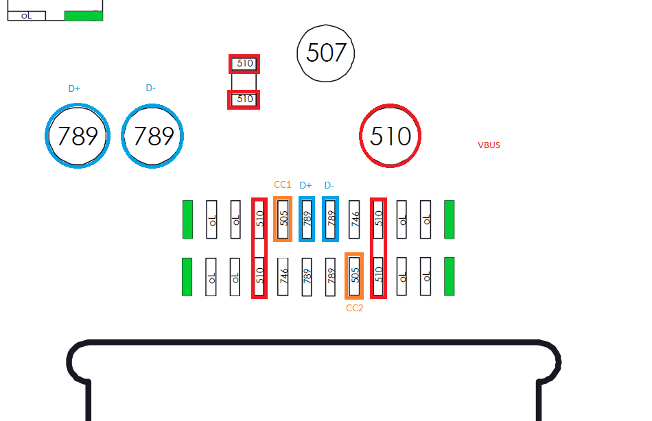
I would check the pins A6 (D+) and A7 (D-) at the usb c connector: (The values are in diode mode)
I have disconnected the EMMC and the battery and plugged it into my PC with tegraRcmGUI running and it did not recognize it in RCM. I also just got in a new RCM jig so tried putting it into RCM with the jig in the right joycon slot + vol. down + power and did not get a result. I unplugged it from my pc and in diode mode I got the following readings
D+ = 1.492 V
D- = 1.51 V
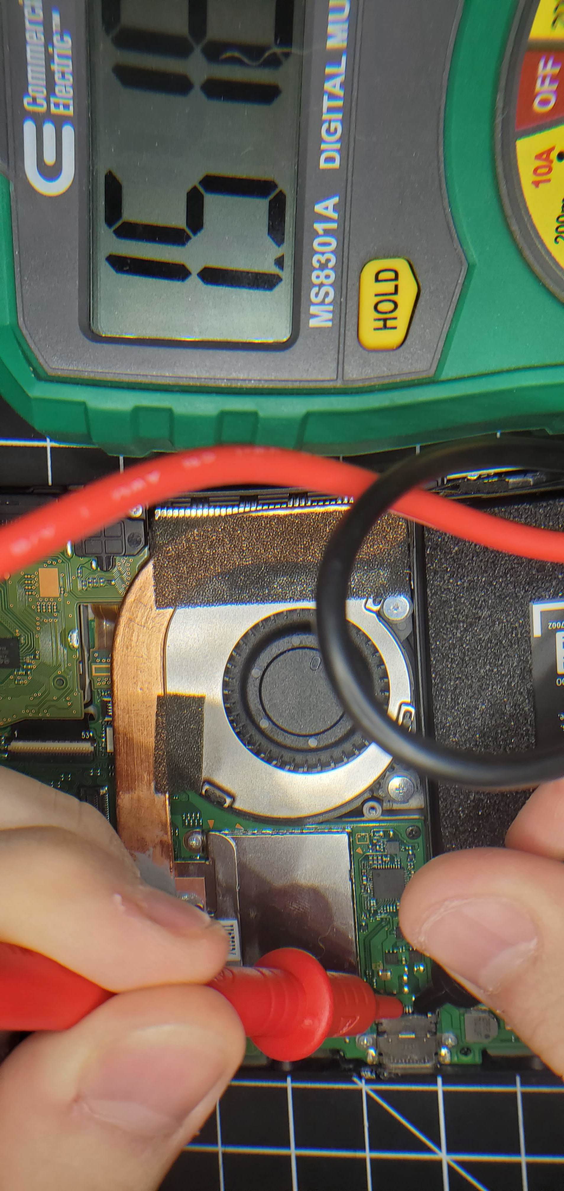
I did this by connecting the black probe to ground (you marked in red) and the red probe on the D- and D+ pins. I am not sure how to interpret the readings I got. I am able to post pictures now so I included a picture of the reading. My USB C charge reader is coming in late, so I will upload info I get from it as soon as it comes in.
For the pins in order from left to right (including the green ones)
01: 0L (Green)
02: 0L
03: 0L
04: N/A (Red)
05: 0L (CC1)
06: 1.8V (D+)
07: 1.4V (D-)
08: 0L (CC2)
09: N/A (Red)
10: 0L
11: 0L
12: 0L (Green)
Edit: I believe the 0L is just saying it is to low to read, so those are roughly 0
Mine only beeps in continuity mode. For diode mode touching the probes together I get 0L and no beep. If I measure at those points I get the same values.
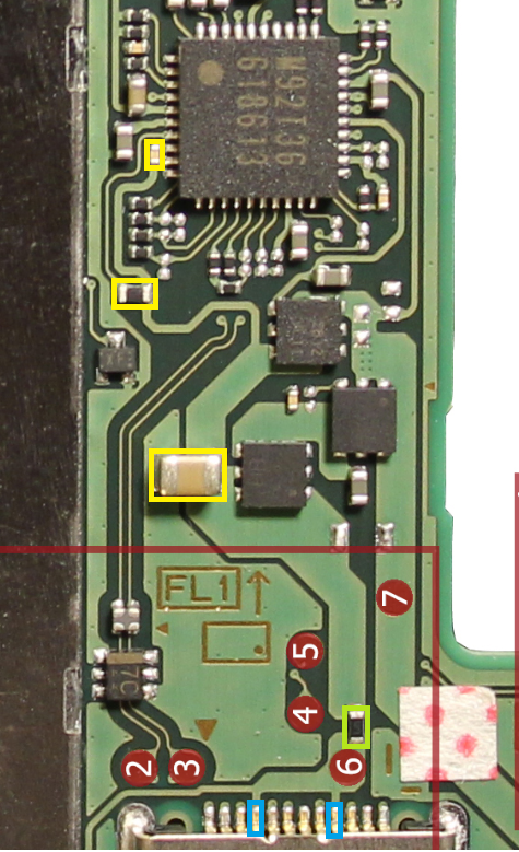
Also it looks look I have a different board version if that makes a difference. My points 4&5 are to the right of the fuse, not to the left. I have board HAC-CPU-20 if that’s what the writing on the board means.
Edit: Also I have been taking all these measurements with EMMC, battery, and USB C cable disconnected.
Diode mode measurements please allways without battery and without any power supply. If another power source is plugged it could damage the multimeter.
The board layouts are different but the basic logics are the same. So the values my vary a bit.
It makes no sence if your multimeter can t differ between 0V and OL.
0V means direct contact = continuity. OL means open line = no continuity.
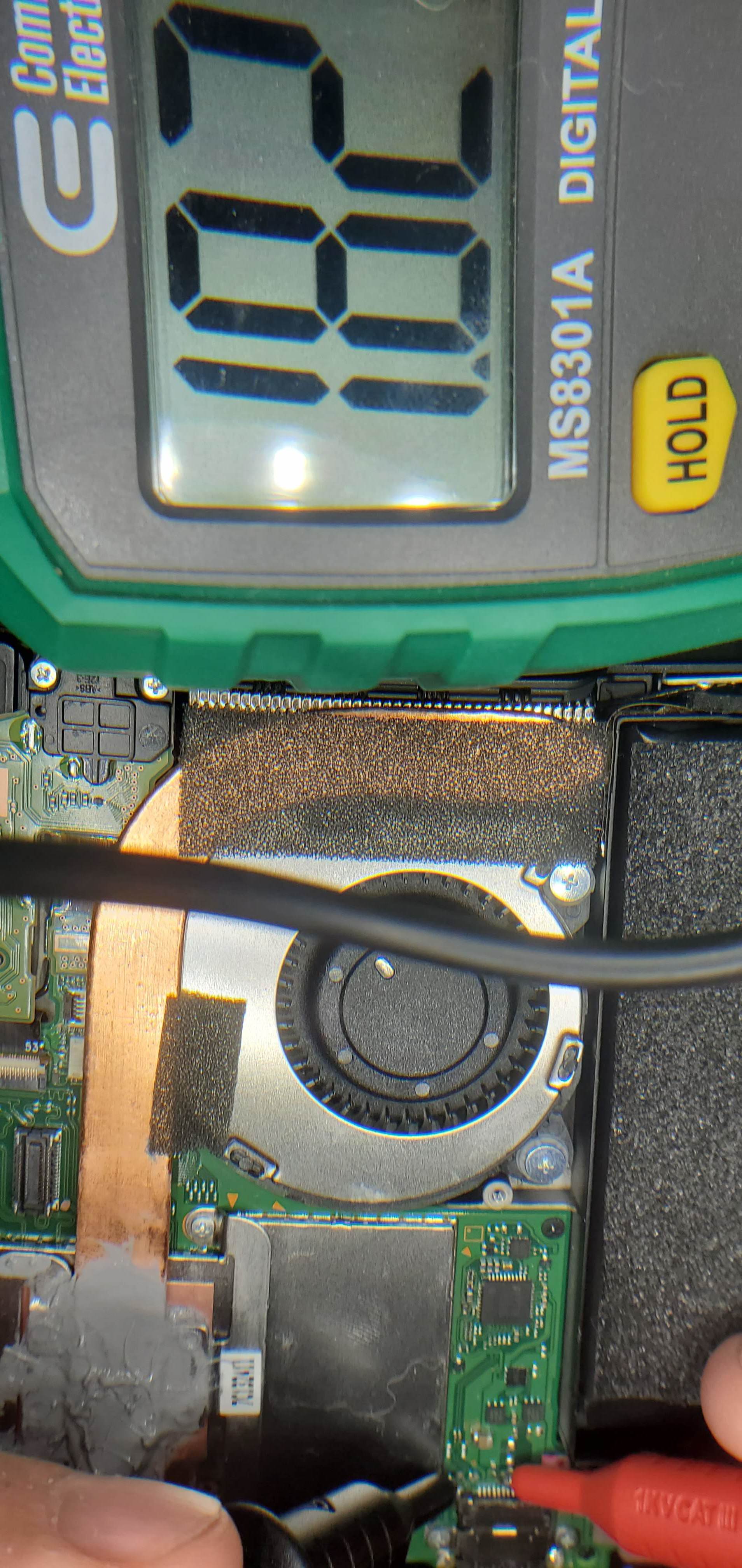
When I try again I got 0.000 but had to move it around a little. I I might have wrote down 0L instead as I had seen 0L so much before. Redoing the measurements from before I get the following (confirmed with 3 readings each)
D- = 1.8V
D+ = 1.4V-1.7V
CC1 = 1.8V
CC2 = 1.8V
Touching Probes = 0.000V
The probes are definitely bad quality as I had to move it around a little to get the right value