I just realized the rar file on my side was corrupted and so the result of the extraction was something called donor_nand but not finalized, instead of a folder.
I would still feel more fault tolerant if I use yours. Could you change the folder permissions to “anyone with the link”?
What do you think about my question about the original HwFly?
I never use any rp2040 based hwfly for mod, hard to tell if mochip caused the issue or the console side.
Also based on exp. Toshiba eMMC has quite unique data0 resistance tolerance compared to other brand.
Then you should have worked your way pre V16 and up…
I said that’s how it used to work on (older FW/erista) but if the boot0/1 are different per sub version (after the decimal place which i think prior they were the same) then you could blow the update fuse/s in which case they would work but if the fuses are blown you’d need to use Hekate to bypass that (which is why I said to work your way up instead of down)
btw you still haven’t verified hardware, as mentioned, bit pointless doing all this if you haven’t done the asbolute miniumum and checked resistance to ground on you primary rails
I don’t think and modchip write junk sdloader into boot0, it just the resistance/hardware setup sometime incompatible for SOC,RAM, EMMC variant. some may need more resistance on dat0 and some may require i2c undervoltage trick(picofly).
BTW, sdloard should load no matter what data corrupted on the emmc as long as glitch success and boot0 interact with modchip
I think if anyone has seen a change as a result of this it’s been a coincidence or it’s caused something else to happen… for whatever reason people in the modding community have a fundamental misunderstanding about line termination and putting resistors in series with I/O… saw much the same nonsense back in the day in the 360 modding scene.
Problem afaict, just based on a skip and scan of the code is the modchip is basically hacked together, based on an already pretty poor SX modchip (although I’ll give the SX hardware the nod and one up in this case) - again just based on a skip and scan of the code, instead of just put a few pennies worth of level shifters on the modchip board they seem to instead be using crude software hacks to work around “damaging the EMMC” … as I touched on earlier two different LL being used and is likely putting the EMMC/s in a very confused state, and most likely the Toshiba IC controller is the worse off at dealing with it (or perhaps even the ECC on these EMMC IC at play too) - then the mosfet on the CPU rail/s which I’ve not looked into, but if they truly are just shorting this rail out as part of the “glitch” then that’s yet more jank, if you gonna hook up the I2C lines to the Switch board, why not just disable/alter boot CPU rail etc as required over I2C (?) instead of shorting it out and if for some reason that’s not possible why not just isolate the inductor physically and have the modchip MCU control it’s output… - anyway, ramble over nothing to do with resistors and more to do with (afaict) janky hardware design with janky software design and then maybe combine with a intermittent/bad hardware install.
@jkyoho are you telling me that installing an original HwFly, in case a non-faulty hardware, might work to boot again the Switch?
I am somewhat confused about this message, I suppose it is an assessment of how bad the clone chip design is and how they should operate instead. Unfortunately, my limited knowledge of the field does not allow me to fully understand your disappointment. If, on the other hand, it was a message referring to me, forgive me for not understanding it
Can we go back on this? I see this also relevant message:
I guess this is something I can do just with a multimeter, right? Or do I need anything else, like oscilloscope or advanced tools to give power?
The problem is that I don’t exactly understand what I need to measure and what values they should have. I also looked for some schematics, but for example this post shows schematics of everything except Emmc (or so it seems to me).
tronicsfixforum .com/t/info-board-diagram-and-part-numbers/91
tronicsfixforum .com/t/switch-no-power/7243
So far, I’ve only tested capacitors with diode mode. Capacitors on Hwfly adapter row have good values, as well as the other for power (around the MAX77812 and USB C). I’ve compered them with this video: youtu.be/svEYsLle40c?si=QmT1rQe3_t8O8t0l&t=207
What can I check?
I am wondering if connecting the switch to the PC and using RCM tool like mentioned here tronicsfixforum .com/t/switch-does-not-start-black-screen-battery-voltage-okay-rcm-found-on-pc/10959 could make sense
Note: I didn’t check Boot0 and Boot1 from @jkyoho, but I am going to try it tomorrow as I left my Emmc reader in another location.
Yeah pretty much, and a slight dig at the picofly software which afaict is actively supporting the dodgy hardware (I’d sooner they blocked the bad hardware with a few simple checks and if people want to take the risk then fork the project with a big bold warning right at the beginning) but that’s just my opinion - software isn’t inherently bad (I think it’s great there is an open source version) but it does seem to me to be based on reverse engineering efforts of an originally pretty bad modchip and bypass process and now together with the bad hardware on the market… I’m not keen hope that clears that up.
No, not at all bud, not aimed at you, me just making the thoughts above known as I expect we are going to see a lot more threads like yours in the coming months which is a shame
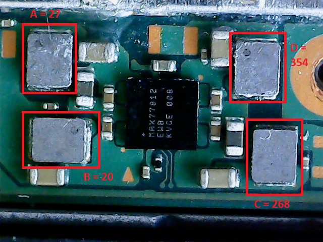
Search the forum regarding 3V3PDR (this is one of the rails for your EMMC) and you’ll find one of it’s many locations, disconnect battery/power and put your black probe on ground and red probe at the other and measure the resistance to ground. Now for your other primary rails do the same thing, but flip the board over and look for the main PMIC (this is a max IC surrounded by inductors, again, search the forum if you unsure of it’s location) and put your red probe on either side of the the inductor (doesn’t matter which side) and measure the resistance to ground and let me know in an image overlay what all your readings were
Ignore this man (this is all just relating to and coming back to the modchip hardware again) the RP IC on your modchip has it’s IO at a fixed 3.3V logic level and as far as i can see and from reasearch there is no register you can change to bring this down so pretty much confirmed unfortunately and as there is no active circuity on your modchip to shift the logic level - at least that I can see. Basically what I’m getting at here is the EMMC on Switch (stock) is operating at 1.8V logic level (as defined by VCCQ) when the modchip modifies the EMMC partition/s and when the relevant line/s go active high and because the modchip is at a fixed 3.3V logic level, then the line/s as a whole are going to be 3.3V, which is likely putting the EMMC IC’s controller in a bit of a confused state when it’s VCCQ level is still 1.8V (which likely defines the logic level) - given how fast modern EMMC’s are I’m not sure you’d see this with a standard meter or not and given that I imagine the EMMC partition modification takes place in probably less than a few secs. But anyway, it probably get’s away with it more often than not but I’m very sure this will not be in the EMMC spec and there is a chance it could cause issues, and based our previous experience here, the toshiba IC’s aren’t great in terms of the tolerance (in unrelated matters)
So, I would imagine it’s either bad luck in your case when it was modifying your EMMC partition/s or an install issue. (or maybe a combination of both, for example if one of your EMMC lines was only partially soldered for example)
My concern now is if you have blown your update fuse then your a bit stuck and basically have to resort back to using the modchip again I’ll wait for your rails measurments and we’ll cross that bridge when we come to it, hopefully we can verify the Switch itself is good and then after the modchip
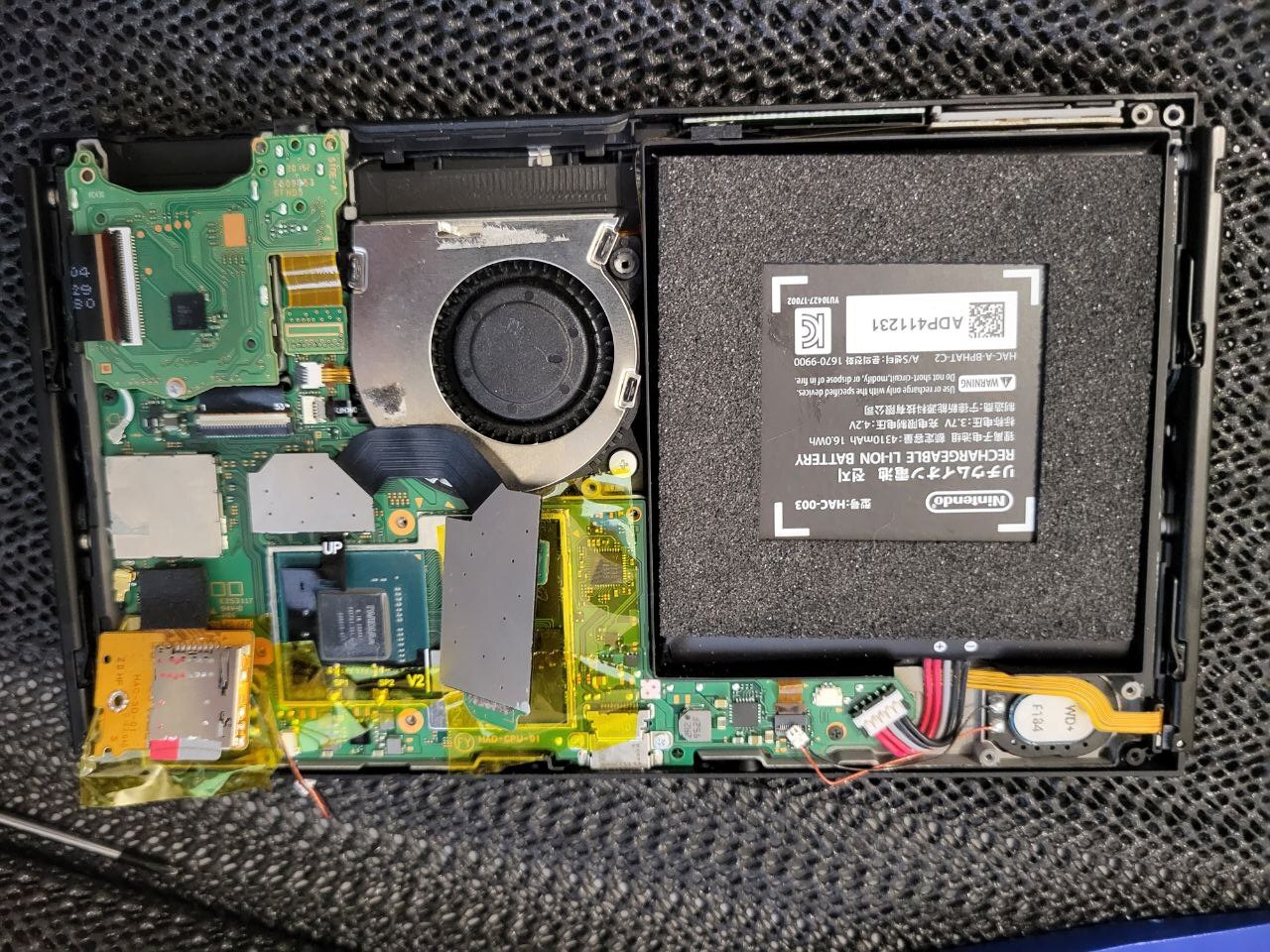
I was doing all the measurements you requested, I was also taking pictures and annotating values on top of the pictures.
When I had to disassemble the console in order to turn the motherboard over and take the other measurements, I first wanted to do a test: as I had my doubts that maybe the flat had been damaged when closing the console, I cleaned everything and soldered on a new adapter that I recently received, also V2.
To my surprise, ‘it works’!
What do I mean by ‘works’? The modchip gives the blue LED and finally manages to glitch, taking me to the ‘No SD card’ screen.
Excellent I say! At least it’s a big step forward.
The problem is that I wanted to backup everything up via Hekete before closing the console. I therefore plugged in the SD card module. I prepared the Hekete + athmosphere package but the problem is that after the glitch (so blue led and then yellow led) a black screen remains.
If I remove the micro sd card from the reader and power on, the “No SD Card” screen is shown successfully.
I tried with 3 different SD cards (256GB, 64GB and 32GB). I have tried formatting with both “SD Card formatter” and “Rufus”.
For the content: I tried an already complete package found in a tutorial, I also tried another package from [KEFIR 709, Atmosphere 1.5.5, hekate 6.0.6].
Nothing, still the same problem.
Do you have an idea of what is going on? I hope for the best, but I’m a bit afraid that something is still messed up.
Thanks!
This isn’t really needed now as you already backed it up with your adapter previously right? (or am I mixing up topics, there has been a lot of picofly problems it seems )
I’d guess either a contact issue at the SD connector on mainboard (?) failing that is there guidance from the modchip install instructions (?)
I’d still proceed in checking the rails as outlined previously just incase. (shared rail with SD and all too, so worth checking anyway)
I want to backup Boot0, Boot1 and Prod keys from Hekate, as I’ve never reached the step where I was able to boot Hekate. The furthest step achieved was to get the modchip to boot correctly at the ‘No SD Card’ screen, never farther.
Not sure if I got it
I’ve seen people running the HwFly RP2040 to “No SD Card” and later, inserting the SD card, progressing.
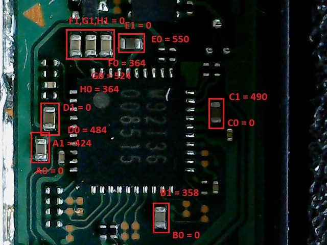
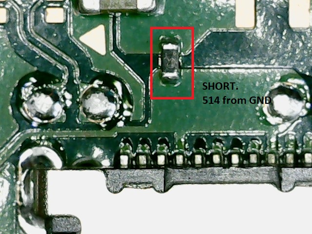
Ok, let me share all the readings I’ve found so far, using diode mode where all the readings are against GND:
I just mean the connector for the SD card flex on the motherboard… people often times break the solder joints for the pins on this connector.
[quote=“minimanimo, post:71, topic:10936”]
Ok, let me share all the readings I’ve found so far, using diode mode where all the readings are against GND:
I’m pretty sure this isn’t what I asked you for what are the a,b,c etc all about is this all just your nomenclature to keep track?
When you can provide the readings I asked for (battery disconnected, black probe on ground, red at relevant point at the points I described etc resistance, not diode and all with the unit of measure in the image ) and I’ll see if i can see a potential issue
Hello
I have the same problem as you have with your switch although i didnt get any resspberry display just black screen from the start(after i installed the chip) and red solid led light.
Even after removing all modification still have black screen and nothing happend.
Did you have any update of your issue?
I know you all want a one click solution to this problem but there isn’t one, in order to help I need rail measurements as I mentioned here or over on this topic
or the many other related topics - I’ll summarise, If the Switch console isn’t booting without the modchip in place then we have to assume the following, 1: the EMMC is physically dead, or 2: the EMMC partition data is corrupt, or 3: hardware fault on the mainboard.Or a combination of all three.
The measurments I ask for can probably identify 1 (to a lesser extent), and 3 (to a greater extent)
2: would require verifying the EMMC data which I’ve covered in the topic here too and/or ensuring modchip hardware is good and then properly installed to potentially resolve, but this requires that 1 and paritcularly 3 have been verified prior (to avoid potential permanent damage)
In the case of the OP, his boot0 parition on the EMMC in all likelihood had been corrupted, we now know that almost for sure, why? because he would have been able to boot stock and seen a boot logo and/or the console would have booted without the modchip in place but he could also have additional hardware issues which could possibly prevent boot too (which the measurments I asked for will all but confirm) and that’s not even taking into account fringe cases, for example, what if one of you guys installing these modchips has chipped the fuel guage IC unbeknownst to you or me (which has similar symptoms)
Regardless, if you aren’t capable of providing the very basic measurments I’m looking for (so I can help you) or you aren’t capable of a bit of a initiative and reading and searching through a few forum threads to make yourself capable… then quite simply you shouldn’t have even attempted the install to begin with (sorry, not trying to be mean but it’s the truth)
Hi, I have almost the same problem - *== after picofly on my patched v1.
I have full backup, could I write required partitions using another hacked pathed v1 or v2? Either I need unpatched to do this. Thanks for answering.
You could connect the patient emmc to another hacked switch and mount the EMMC with Hekate over USB and on PC and write the said partition using nxnandmanager (easiest way of doing it)
Curious, did it work for a long period, or start acting like this early. Or did it behave like this following an update?
If you do write the partitions, start with the boot0 parittion on it’s own first and if you can let me know if this resolves your problem, as I’m curious if that’s the running theme in these cases.
Although this assumes your backup is the same HOS version number as what the system was was actually on at the time of the problem. If they are different versions you’ll have to write all partitions.
If the backup is indeed a lower OS version, then it’s possible you’ve blown the update fuse (you’ll have to check on this if the modchip prevents this by default) if the backup is a different version and if the fuse has blown then you’ll need to use a modchip on your patient again to get it out of this state or alternatively if you have your keys you’d have to generate the files for the version your Switch was on at the time of the problem or just the newst OS version
Hi @Severence,
I returned following a break (unfortunately, only a small part due to the summer holidays). Nevertheless, I am on my way to take measurements.
I don’t know if this message is directed at me, however, so far I have never complained but rather always politely asked and thanked for the support… and I continue to do so
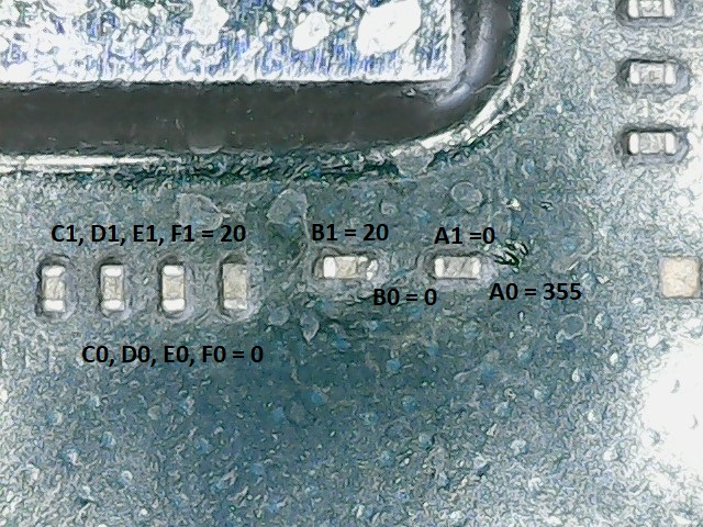
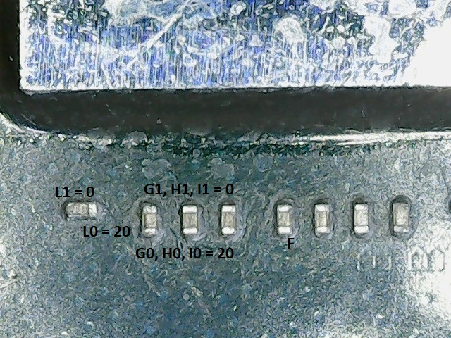
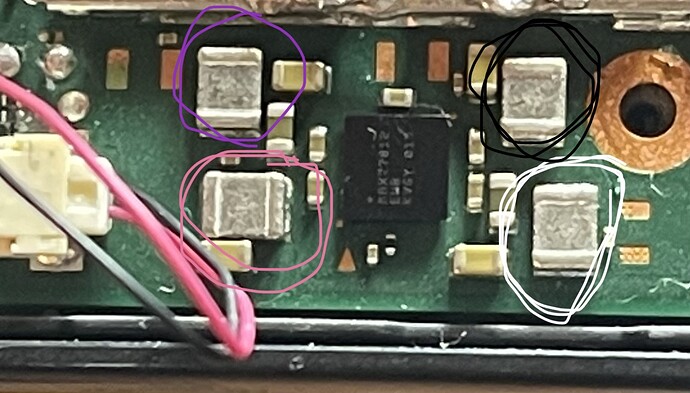
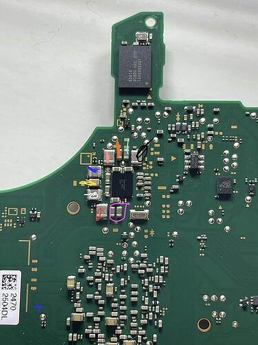
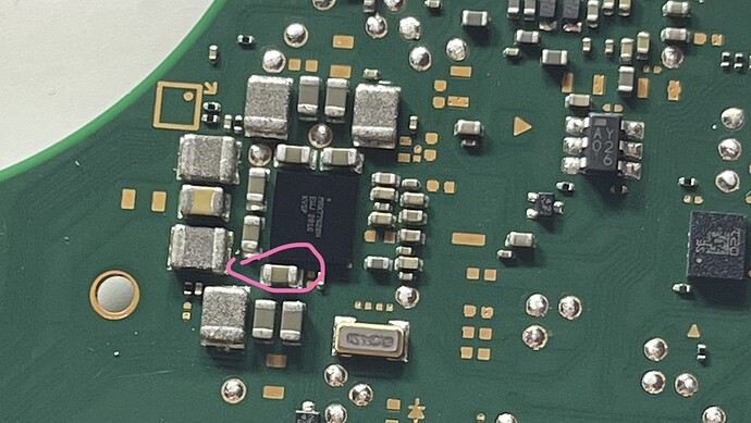
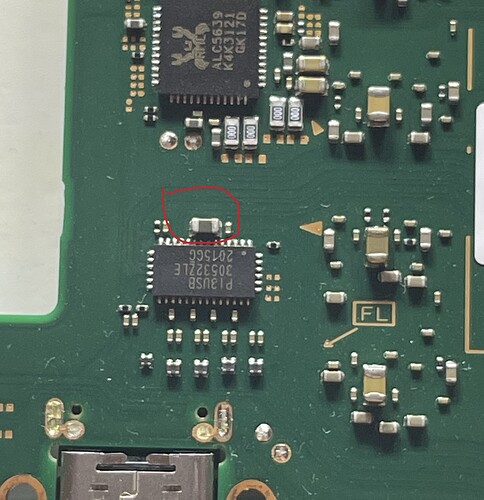
Having said that, I borrow the images from the topic Picofly installed worked first time niw switch fried of the person who has the same problem as me, and write my own readings instead. All readings are with EMMC attached to the board.
Also:
white both sides 57Ω
Purple both sides 12.6 Ω
pink both sides 12.6 Ω
Black has no reading
White both sides 14.4 Ω
Yellow left 14.4Ω, right 0.2 Ω
Blue both sides top 14.2 Ω
Peach top 16.2 kΩ
Orange top 16.2 kΩ, bottom 0.4Ω
Cyano top 4.22 kΩ, bottom 0.4 Ω
Black both sides 4.22 kΩ
Purple boths: bottom 9 Ω circa and top 0.5 Ω
Red 8.8 Ω
Pink is left >20 kΩ (gets bigger every second, goes over 100 kΩ easy), right 0.4 Ω
Red left 125 kΩ circa, right 0.4 Ω
Correct me if I am wrong, but from reading your comments in the other thread I guess that my readings are good, do you confirm?
Let me know if more readings are needed, I’ll leave the motherboard disconnected for the time being.
If the problem is not the EMMC and the hardware readings are fine, it’s even more likely that the problem is on the partitions, right? Hoping for Boot0 and possible to recover (so far I’ve just tried once to write a Boot0 and Boot1 generated on my own, before getting the ones from @jkyoho)
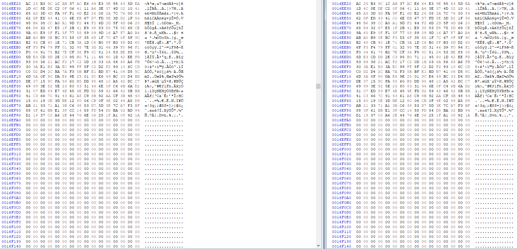
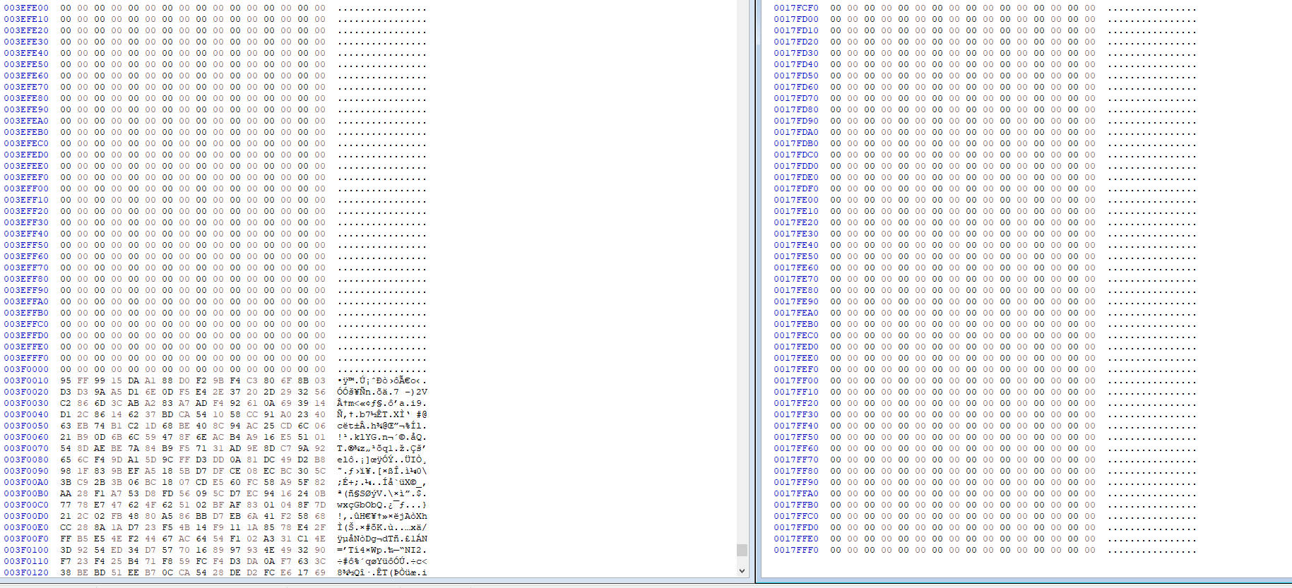
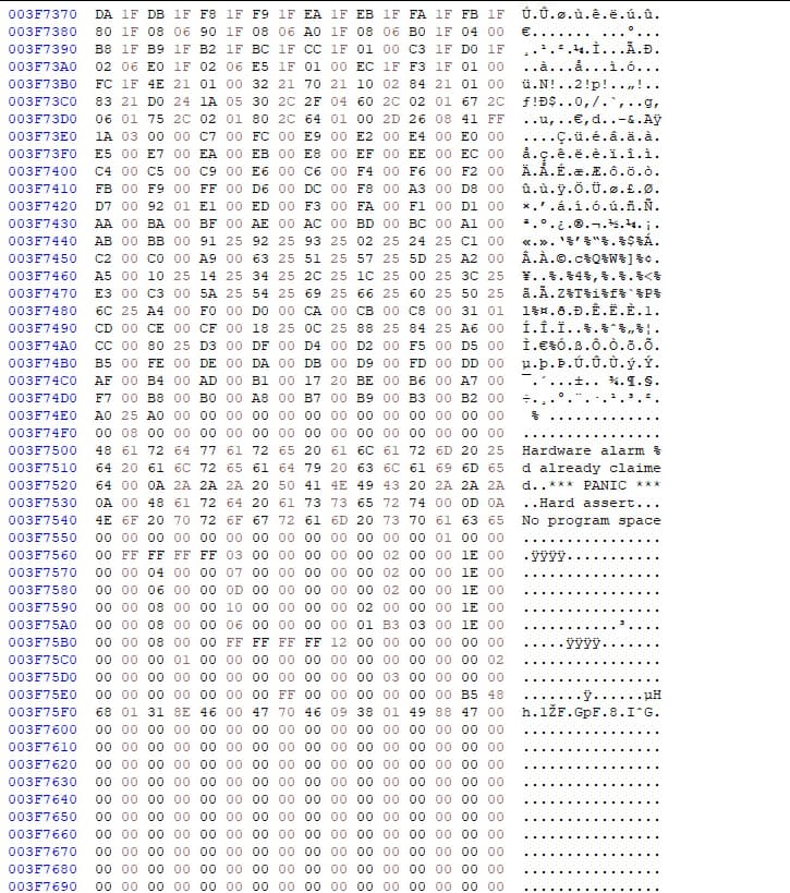
I was comparing the Boot0 you provided with mine.
Apart of the difference in size (1,5 MB yours, 4 MB mine) I also see there a difference in the amount of data (I was thinking that most of 4 MB were just zeros).
On the Top, the amount of data finishes at same offset and looks also pretty the same.
However, yours closes at 0017FFF0 but mine continues for a while and have some data!
But maybe is just a debug string and %d is actually replaced with a digit in case of needs.
Do you know if data after 0017FFF0 are actually important? Or can I just try to write your Boot0 and Boot1 as it is on my EMMC (once we assured there is no hardware problem)?
Remember that I can only flash via ubuntu using the MmcblkNX, don’t know if may cause problems the shrinked file sizes.