while working on the pi3usb i think i applied to much pressure on the ic. now the switch showes a blue screen. after installing an sxcore the “no sd” screen has artefacts. do you think i damaged the ram, or managed to move the ram and shorted out solderballs?
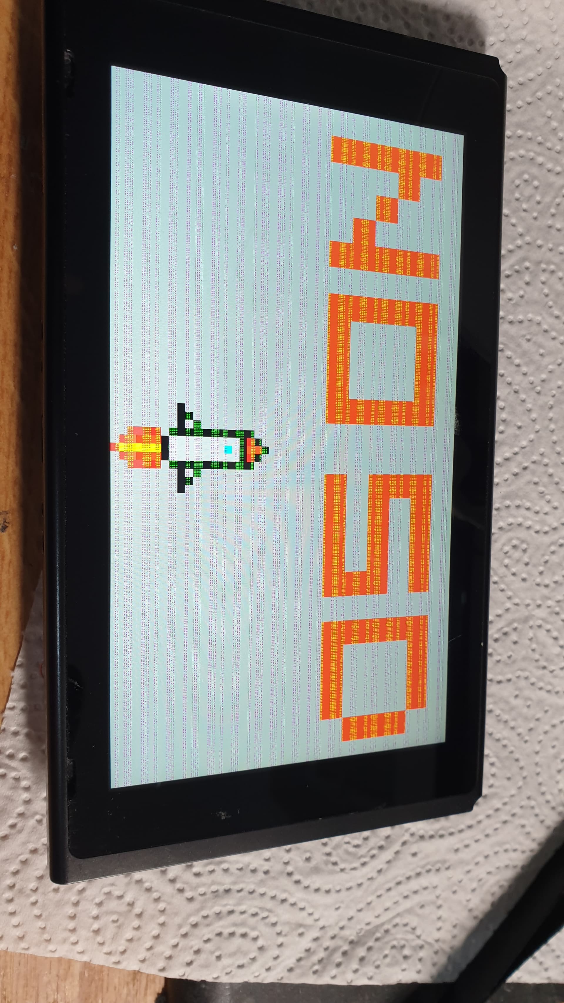
inserting a sdcard leads to a blackscreen when the led turn green.
I would guess Ram has become disjointed during your P13 rework.
Thanks for sharing this, this is a perfect example of why you don’t press down IC’s during reflow (at all) - your bringing a board (which is partially glass) up to a softened state, applying pressure to an IC within this time period will not only have a negative impact on the long term life of the IC itself (ask yourself what happens to the insides of the chips which are glass like in nature when all play between it an the board is removed - and especially when said board is flexed over the months) but also the entire board itself.
Word of warning for others, and I won’t name names, but if your watching video by YT’s beginning with an “N” or a “C” …just do the opposite…
I’d remove the P13 for now, attempt a ram reflow and test, if it works, put the P13 back on in a more conventional manner 

2 Likes
thx ver much. for qfn chips i use a t12-bc1 tip. but this tip, eventhough it is the smallest, doesnt fit between the caps/resistors and the ic. do you know if there is a even smaller tip which would fit, or are you suggesting to remove the components around the ics and put them back later on?
will try to reflow the ram tomorrow.
I use ordinarily a JL02 or JS02 for something like this but tbh I won’t run round with the iron in most cases as, if the pads on the board have been properly prepped (and you can use a larger tip without the chip on here) then it doesn;t need it. you can give it a gentle nudge downward during reflow if the solder is oxidized (IE: chip is refusing to localize) , but just don’t hold and press down.
Nah, leave them be ![]()
Was just my first thought, failing this, it would unfortunately be the SoC next ![]() given the associated SD lines here
given the associated SD lines here
1 Like
i almost never managed to solder the pi3 like that. after alot of failled attemts i started applying pressure onto the ic. this way it almost always workes the first try. with those tip i also tried to run around the ic but i couldnt manage to create a proper connection. but i will give your method a try again the next few times.
a picture of properly prepped pads would be sweet. maybe a whole video on how you solder the pi3?
I understand the tempatation, and if it was the only way you found that worked I can definately understand why you’d try and stick with it… but it comes at the expense of situations like this ![]() this is one of those situations that takes a lot of practice, if you have a scrap unfixable donor board and IC, just repeat this process x20 times, prep the pads, solder the chip, look at it side on and test continuity (from those upper visible contacts on the IC to their desitinations) clean rinse repeat
this is one of those situations that takes a lot of practice, if you have a scrap unfixable donor board and IC, just repeat this process x20 times, prep the pads, solder the chip, look at it side on and test continuity (from those upper visible contacts on the IC to their desitinations) clean rinse repeat ![]() you’ll get it in the end. if your still having trouble, try prepping the IC itself also with solder (at a lower than normal temp) prior which will make things easier
you’ll get it in the end. if your still having trouble, try prepping the IC itself also with solder (at a lower than normal temp) prior which will make things easier
I wish I had the the proper camera for my microscope and I’d make proper video tutorials on such subjects, but unfortunately I don’t yet… maybe sometime down the line ![]()
1 Like
Reflowed the memory and the switch is running again. Also delivering image to the tv. But had to press on the ic 
Can you tell me if your problem was solved and what did you do since I have the same problem with my v2 switch after installing hwfly.