Switch came in with a bad USB-C no power nor no charging, swapped the port did my tests whilst it was off, noticed a few shorted caps but didn’t think I had IC’s that were faulty as someone on here mentioned they could be low resistance to ground.
These are the caps that are shorted, the console after I put on the new USB C showed a charging symbol on the corner but was charging at 0.41 amps then dropped to 0.15 amps and stayed there for a while, nothing on the screen anymore prompted to boot and still nothing.
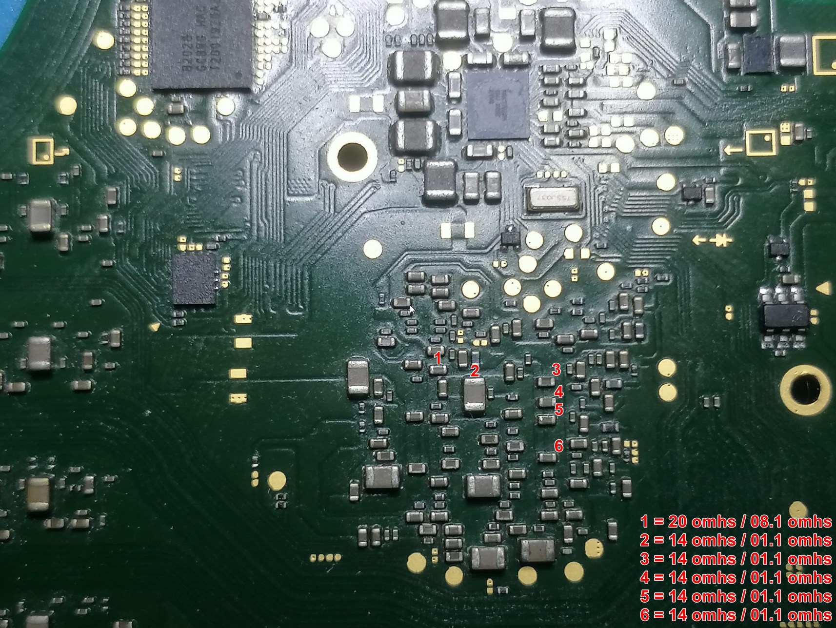
Disconnected the battery and then tried again and the BSoD appeared checked the back of the APU and there are a bunch of shorted caps in the picture above.
Is this a fixable device or can we assume its dead is there anything you guys know that might help me fix it? it’s for an autistic child so I really would like to get it fixed for them.
I would check your markt spots in diode mode again. The components have low resistance to ground and they can easily misstaken as shorted to ground in continuity mode. My measurements in this spots are between 40 and 90 mV.
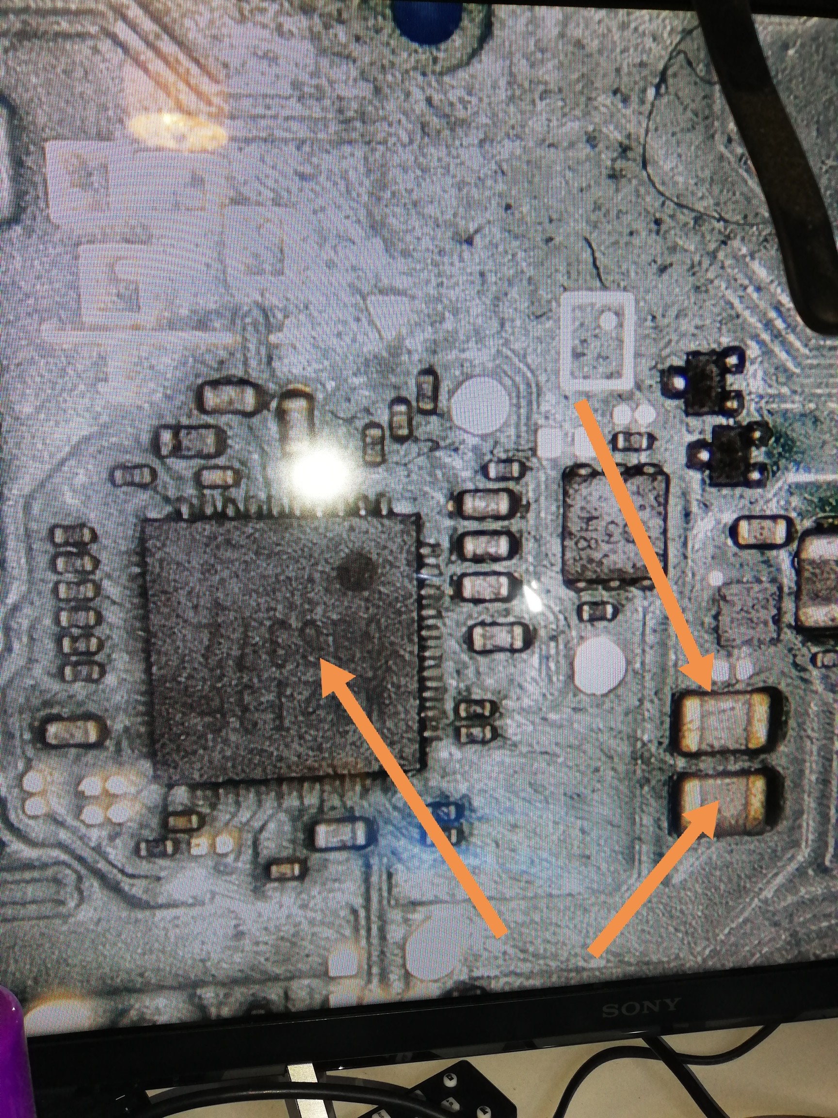
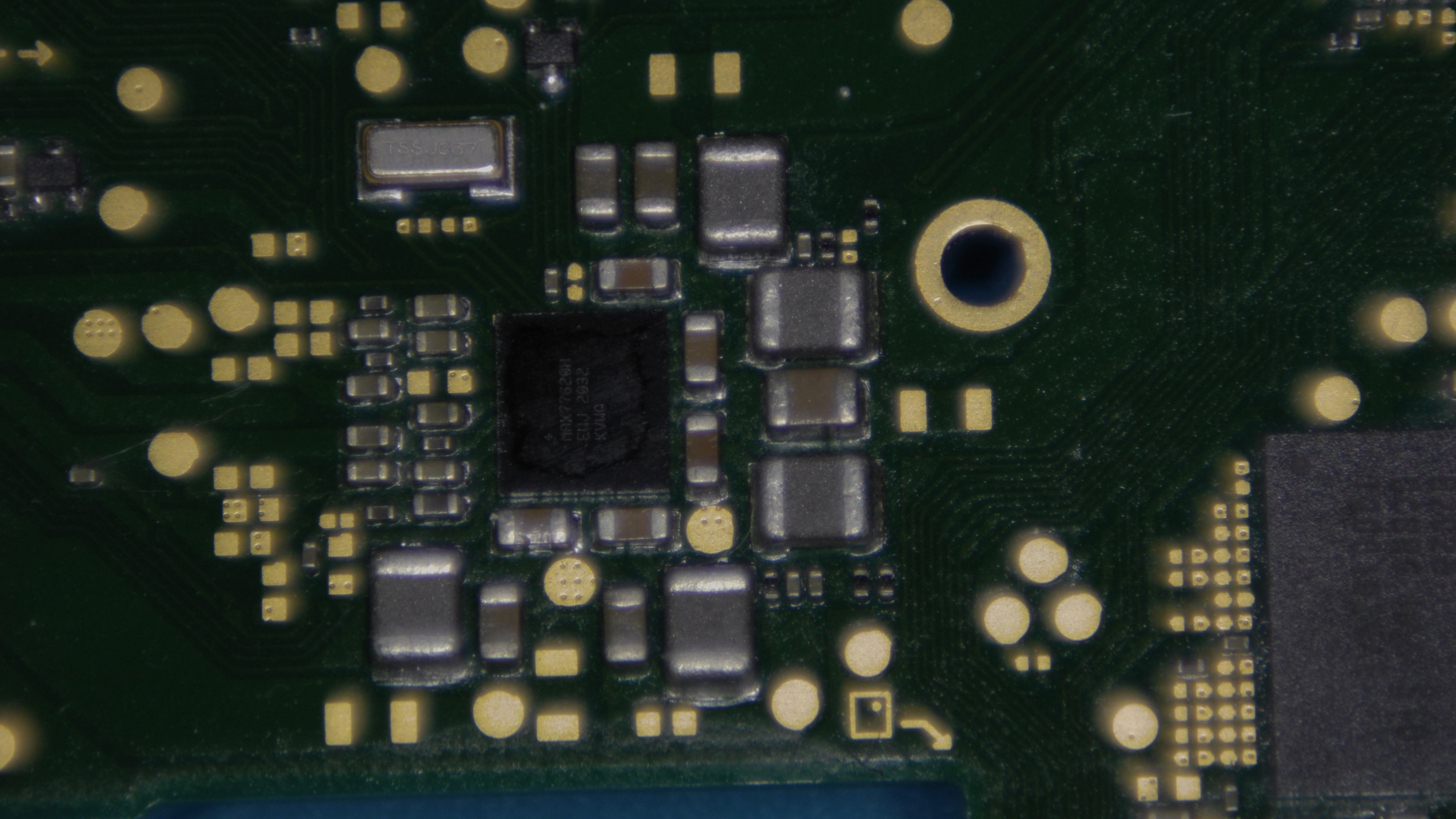
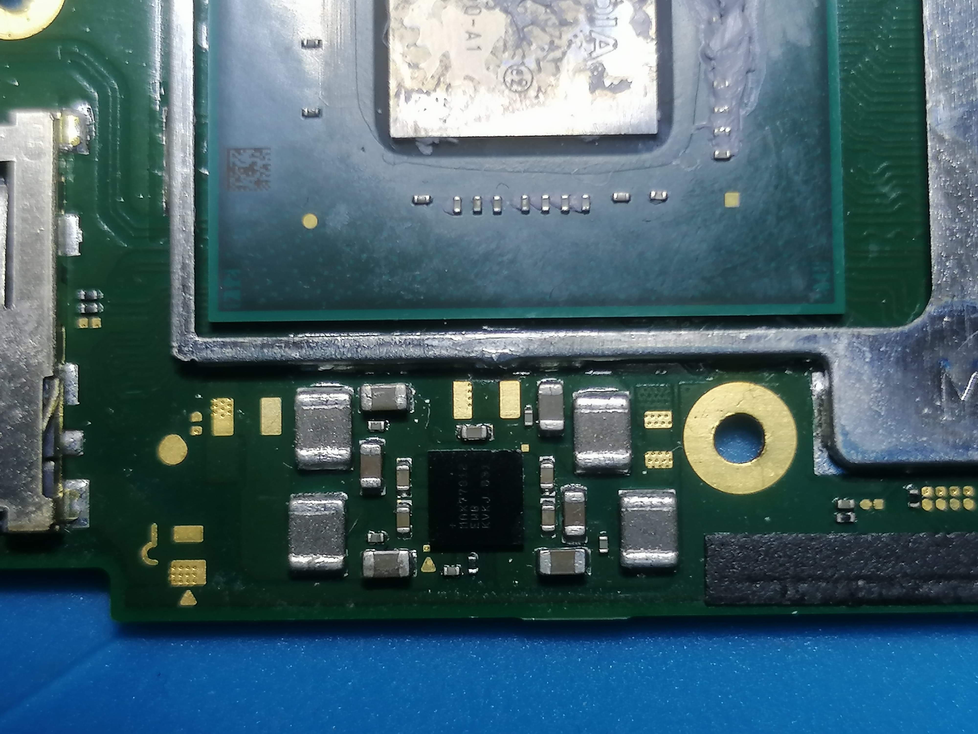
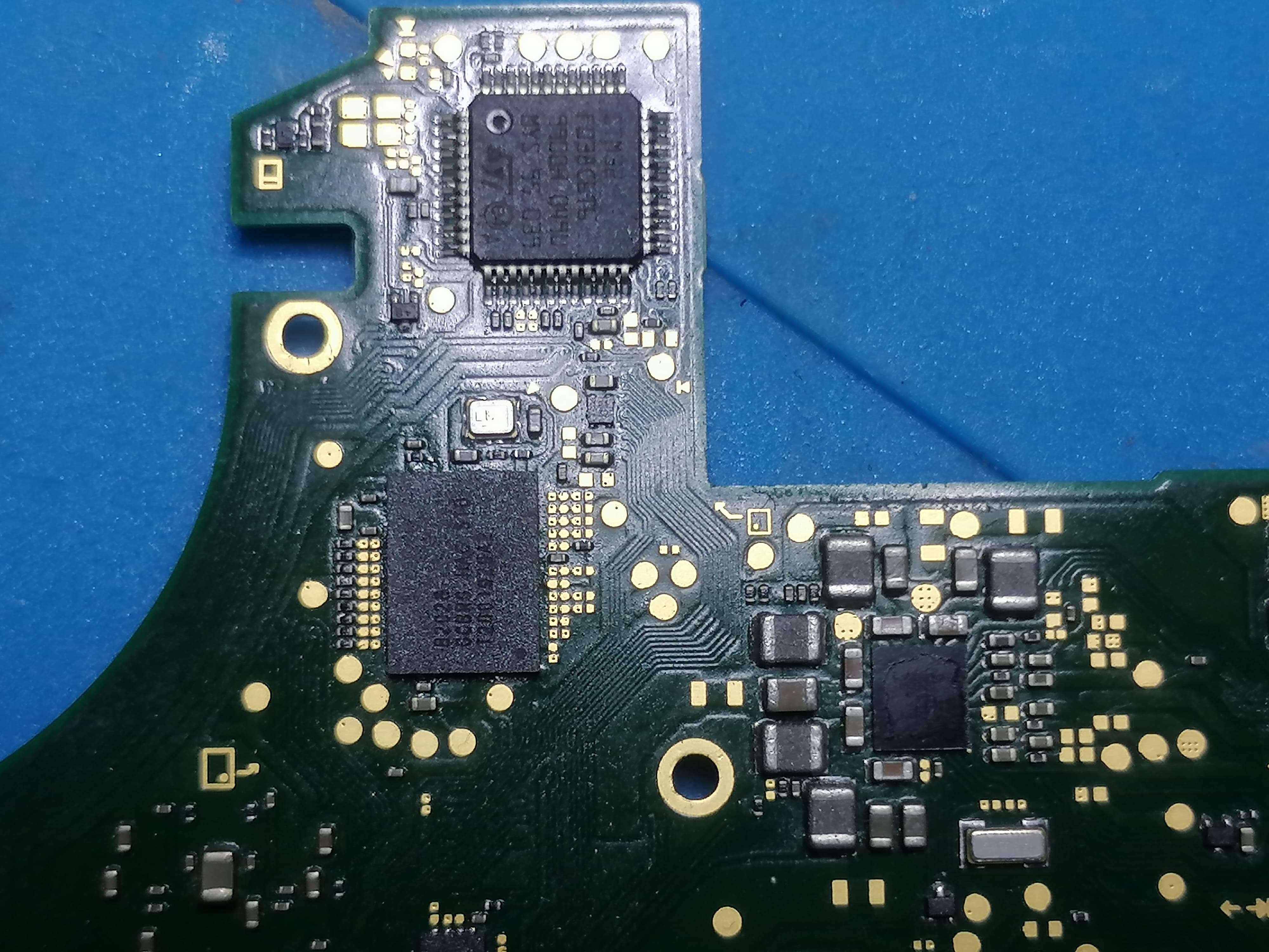
A bad usb-c leads often to a shorted/bad m92t36. I would check the caps around this ic for shorts.
Tested around the M92 IC - it all seems fine to me - it still takes a charge atm, it’s just stuck on a blue screen of death atm. Can a fault M92 or BQ cause it to BSoD I don’t want to attempt a reflow and I’m useless at reballing just in case the APU is fine.
IMO it’s completely pointless taking diode mode readings in these situations.
What is you resistance to ground on the areas you think were shorted earlier?
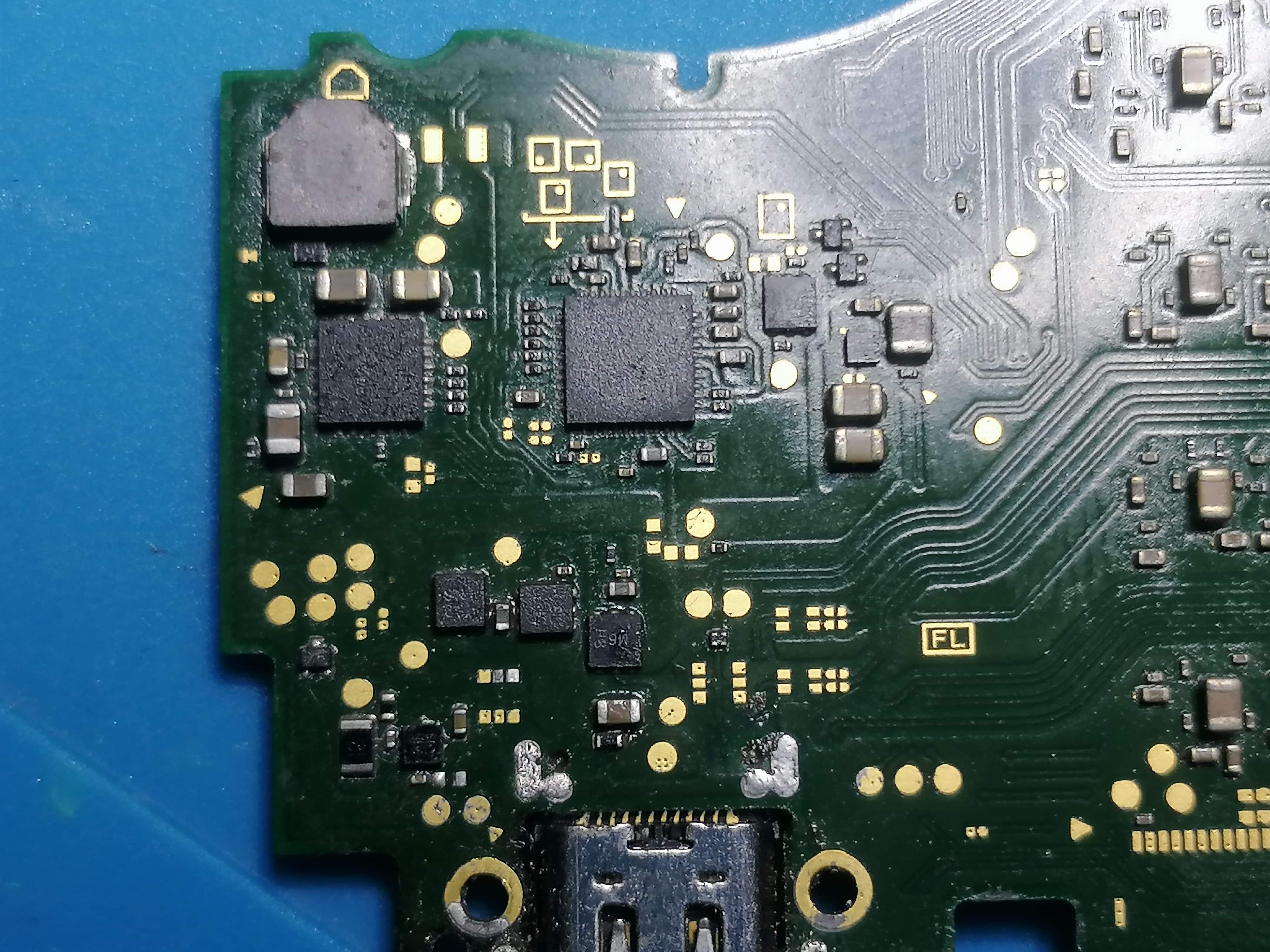
These are Inductors (just so you know)
Remove and wick all low melt solder used in your prior repairs, this stuff causes nothing but problems, particulaly the cheap chinese stuff. Instead use regular [Genuine] leaded solder.
Then after, can you provide a nice clear picture of the fuel gauge on the board so i can inspect, in good light and cleaned board.
These are as good as they are getting unfortunately, I have a HD camera hooked up to an HD monitor and when I take a picture with the camera they come out crap - if I use a phone it looks faded.
Thanks for your reply and hope these pictures help.
As for the resistance to ground the unusual thing is some of the components that were showing ground are now not showing ground, especially the ones around the M92 and BQ IC’s from the previous pictures.
On the pictures above the only ones that are showing ground are the three on the left and they are showing 0.15 omhs black probe on ground and 0.22 omhs red probe to ground.
The inductors? behind the APU black probe on ground and 01.1 / 14.6 omhs and red probe on ground 01.2 / 18.1 but both drop from the higher value by 0.01 omh the longer the probe stays on it.
Also I only applied the low melt to the USB C port and cleaned everything up around that area. I haven’t replaced or removed any of these chips yet.
I must admit I don’t understand enough about these readings.
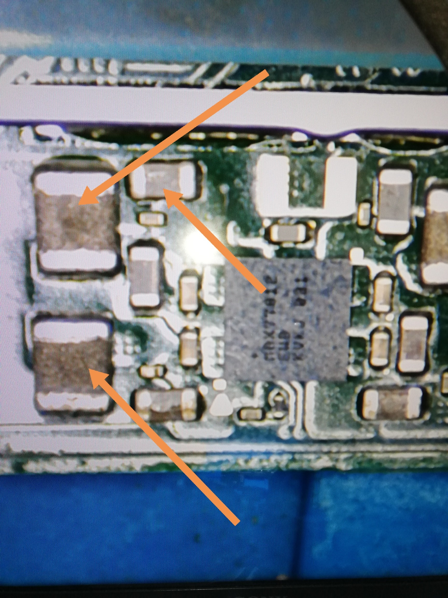
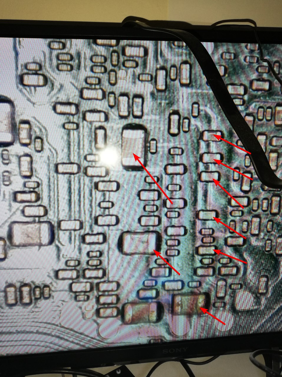
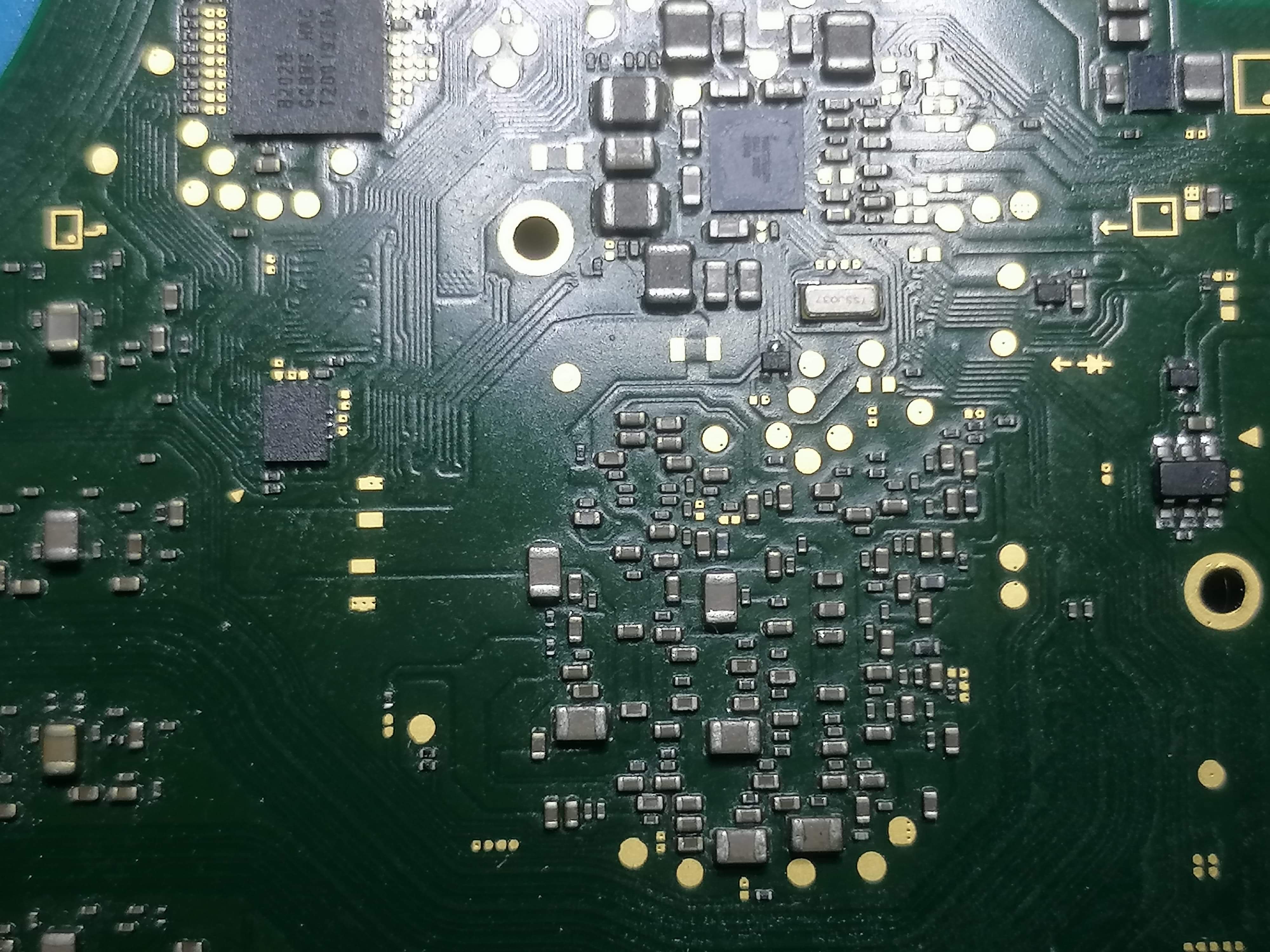
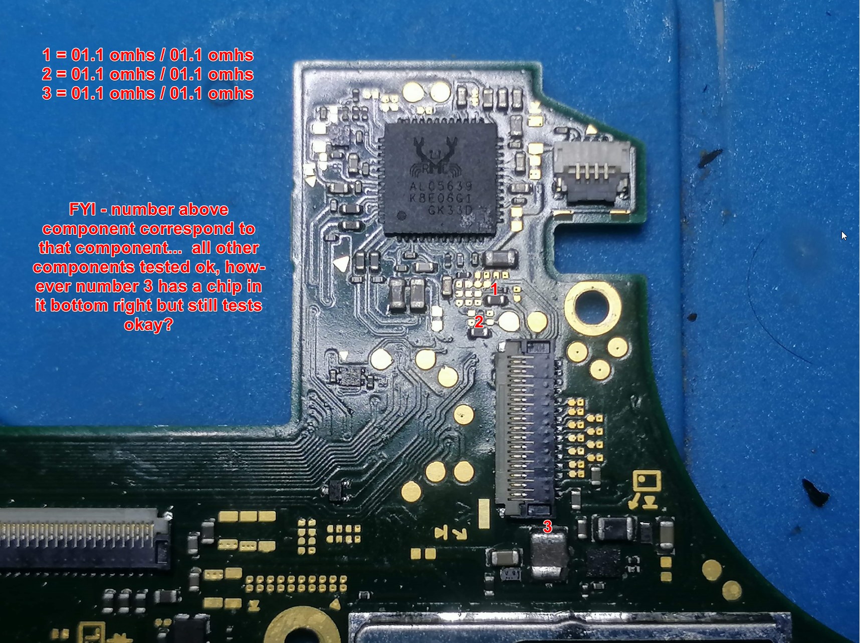
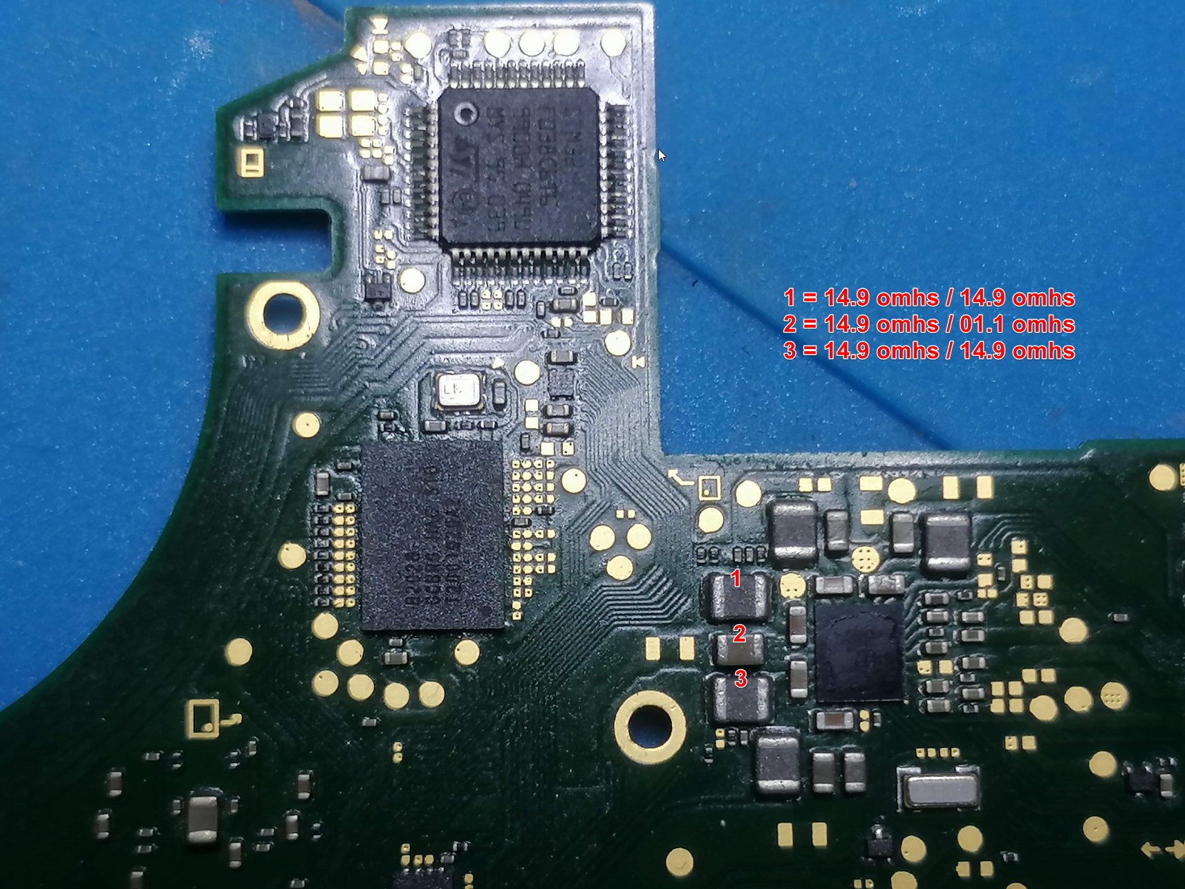
I think you got me wrong. On you third picture you marked two coils and cap left to the MAX77620A. And on the fourth picture you pointed at several caps on the backside of the soc.
This are lines with low resistance to ground and that s why they are often misstaken as shorted to ground.
If you check in diode mode (or as Severence prefer: in resistance mode) this spots, you can rule out if this are real shorts or not. From my experience the expected diode mode values should be something between 40 and 90 mV.
To narrow a possible failure down at the m92t36 (at your first picture) I would check in the first step the surrounding bigger caps for shorts.
I’ve had to put the switch lite back together now, I’ll ask the customer for her permission to continue to work on it but she’s asked to collect it and find somewhere else she’s getting impatient.
I appreciate the replies guys, I’ll update the thread if she allows me to continue to work on it.
I have the console for a few more days she said she can’t afford to replace it and was getting frustrated I managed to calm her down and convince her that staying the course is the best option… so I’ll be pulling it apart tonight.
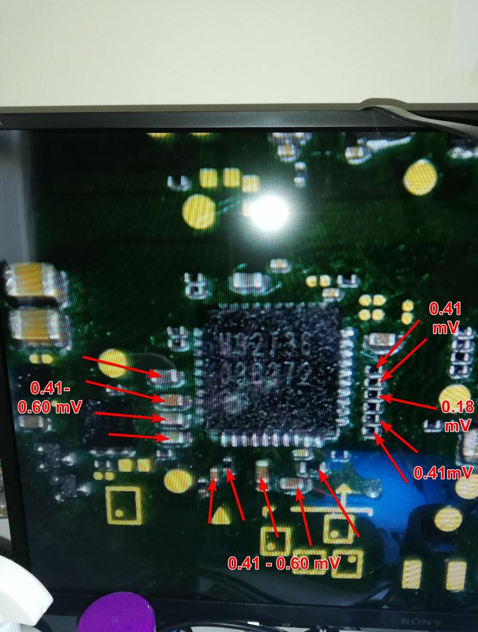
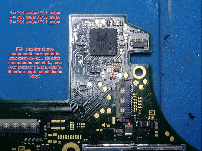
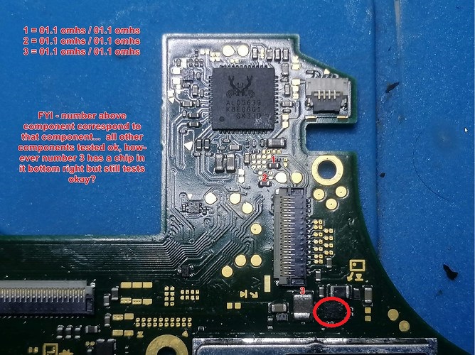
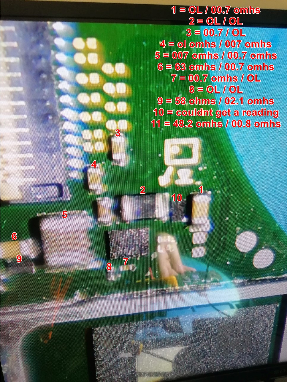
Not sure if these pictures are any better used my GF phone. I’ve added some values to the end of the post for the components that are showing shorted. Hope this helps thanks for any help you have provided so far I appreciate it.
The readings in this image represent your problem, unfortunately I don’t have a Lite board here so don’t know what rail it represents, can you buzz out these shorted components to a pin on either the BQ or M92 IC so i might check? either that or mybe someone else with a Lite board on hand can double check and chime in
Afaict the measurments in your other images are fine off the top of my head.
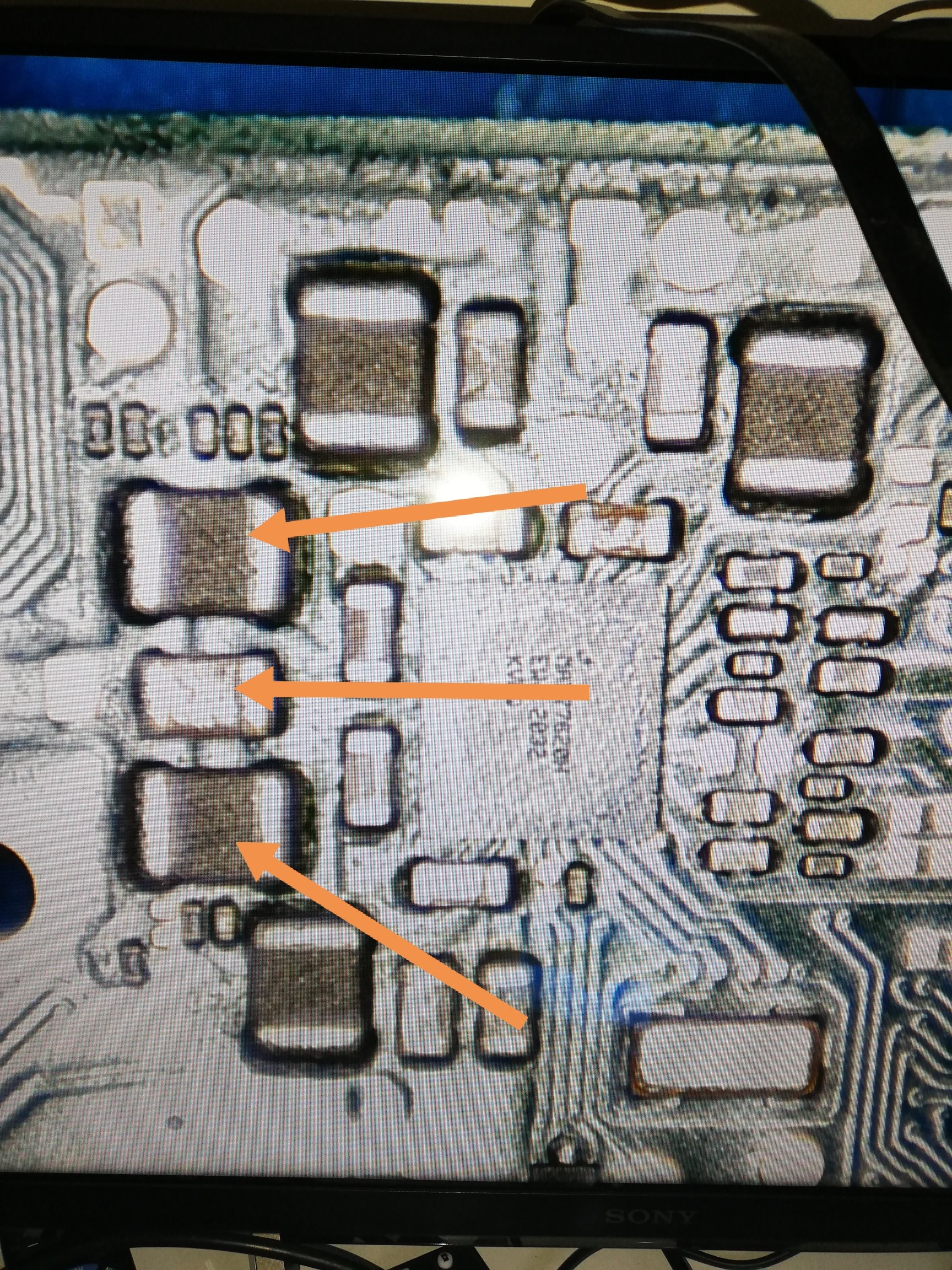
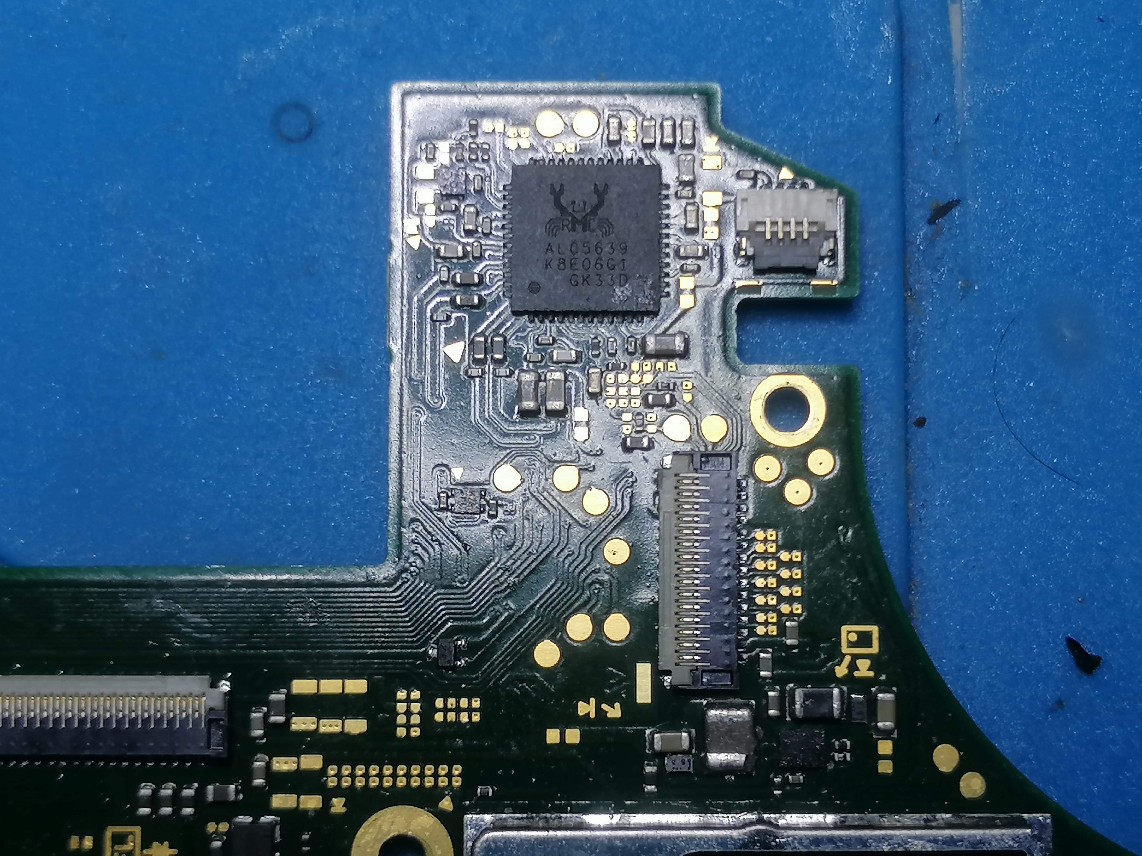
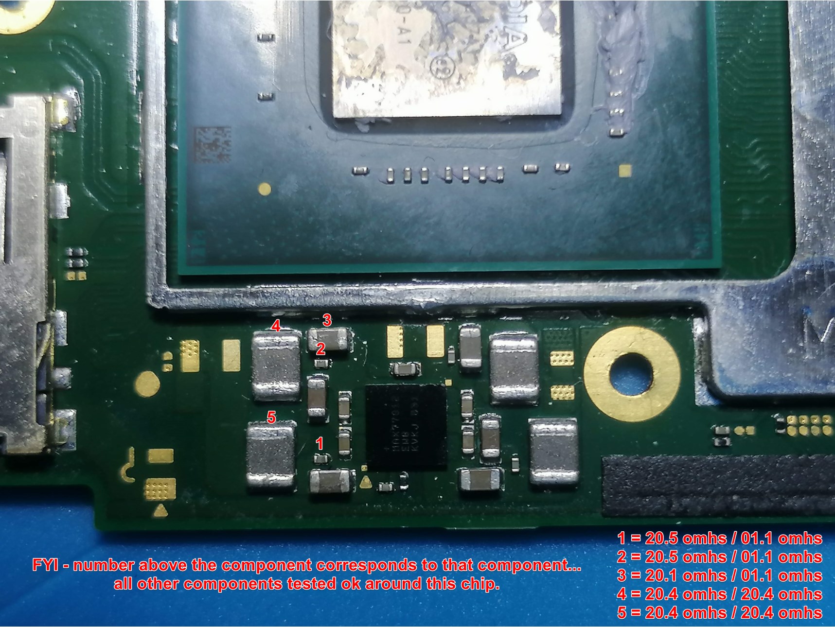
Actually looking a little closer at the image, does the following highlighted IC read “8316” on it?
If yes, then measuring resistance to ground on either side of the inductor (which is chipped on your board) it normally measures approx 2.5 to 8 ohms relative to ground on my regular switch boards, but given the inductor is chipped on your board, perhaps it’s an indication of a fault with either the IC here or possibly the diode/s, further tests needed in this area on the surounding components
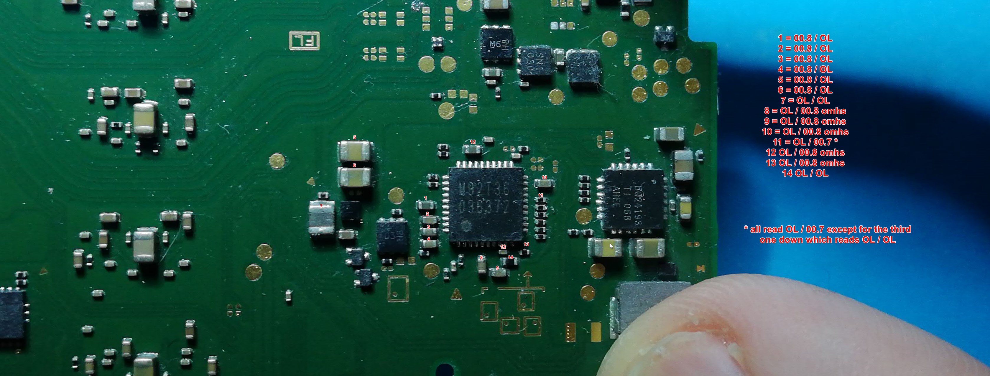
This is what I have been able to measure in that area number 9 was knocked of by me accidently trying to take a measurement, I’ve put it back and made sure all the readings were the same and they are.
As for that chip you mentioned yes it is 8316 on it.
I’ll check these measurments for you as soon as I can,
In the meantime, Can you take Calvin’s advice and measure resistance to ground at the M92 IC on the surrounding larger caps, IE: correspondnig with pin6 etc
Just so we can rule that out as a potential issue.
There is a few areas there that I know off the top of my head where your readings are not correct, for example the cap which correlates with pin 6 (3V3PDR) should read in the K ohm not OL
And the cap which is on 1V8PDR (you have it numbered 10) should read approx 10k.
perhaps it’s a probing issue, can you try taking those readings again on these rails? (black probe on ground)
K so I just checked your readings and they don’t seem right when comparing with my regular switch boards.
With red probe on ground the diode (you’ve numbered 9) measures approx 600ohm and the other one (you’ve labeled 10) measures approx 80K
So either something else is putting a fault here or the IC or diodes are to blame.
I would also replace that inductor also, make sure to shield the connector (piece of metal like what is covering the SoC)
Word of warning though, if the IC is not the caause of the fault you will require tools and equipment in order to reball the IC, you’ve can’t just tin it and directly solder it back to the board(or you’ll risk killing it permanently)
These measurments are also not good… guess we’ll come back to this after.
Before going any further with the above though, can you put your black probe on ground and your red probe on either side of the large inductor next to BQ IC (doesn’t matter which side you choose) and let me know your reading so I can check your SYS rail.
Black on ground and red on the first large inductor, from left to right reads 01.1 / OL - OL / 01.1 - the OL start of in the 100k ohms but then quickly rises to OL.
9 reads 600-713 ohms
10 reads 90-100 ohms
With the inductor that is chipped off. I do not have a replacement as of yet. I’m using 2 million on my multitester btw