You can typically find them over on badcaps forum, if not lemme know which and i’ll PM them if i have them
tbh you can really get into the weeds on the subject of selecting an appropriate specced inductor. you can see in the IC datasheet they recommend this
Nintendo likely didn’t stray too far from this one specs wise when selecting their one, so you could compare freq, max current, resistance etc…
but tbh, provided the Inductance is the same and the package size is the same or close then pretty much any will work and I wouldn’t read too much into it
Ordered the parts just waiting for them to arrive, had to order some new ones as the first lot I ordered were maxed out at 50mA and according the datasheet it requires 1amp at least - got my new auto ranging tester as well so I’ll go through and make sure all the readings I have given you before are all correct and not dodgy meter readings… I’ll be in touch when I have done them.
Thanks again for all your help, I appreciate it @Severence
@Severence the part finally arrived today I’ve replaced the inductor that chipped and you recommended I take off in one of the above posts… am I good to test the LCD now? or is there something else you want me to do?
PS my auto tester arrived as well no more manual settings
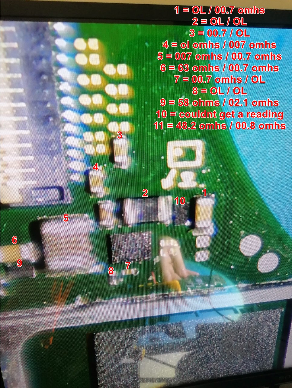
Can you take those same measurements around the M9 IC again now you have your new meter so I can verify, I’m hoping your readings on 1V8PDR (10) go up and it was a meter issue previously.
Can you also do the same on one side of the inductor by BQ relative to ground.
Also, looking closer at your above image, is that corrosion around the BQ IC?
Inductor was reading 0.2 ohms / 0.4 ohms - you said relative to ground I was unsure so I probed it to ground and both sides are beeping to ground?
As for the corrosion I am unsure if it was corrosion we removed that chip if you remember during our initial tests, I don’t think it is as the board didn’t come in for water damage it was to replace the USB the pins were chewed up and crossed over, I managed to get it to boot and some life in it, informed the customer and then that’s when the problems started not charging so I resoldered the port and then charging at 0.43 amps but with a blue screen.
I don’t like this reading, I was hoping it would resolve itself with either your new meter and the resolution of the other faults.
Are you sure? this is the same Inductor (SYS rail) that the short was previously resolved by removing the diode, If the short has returned then you have to restart the process of removing the Inductor and seeing which side of the pad is short to ground, you aren’t simply measuring across it are you?
Your readings on 1V8PDR don’t inspire confidence though and make me start thinking possibly Ram, SoC or maybe even Fuel gauge (though a bad fuel gauge won’t cause issues on the rail in quesion) issues as a result of too much heat or possibly a knock or damage (which will result in BSOD) The fuel gauge is the same as on regular switch board, can you take some photos of that area for me
Just incase a tip, don’t take measurments on the board while it is still hot or warm as they will skew your reaadings.
No idea if that’s your issue here, but if your reading here remains 1.9k, I’d remove the BQ IC once again and see if the reading increases (back to approx 7K or greater)
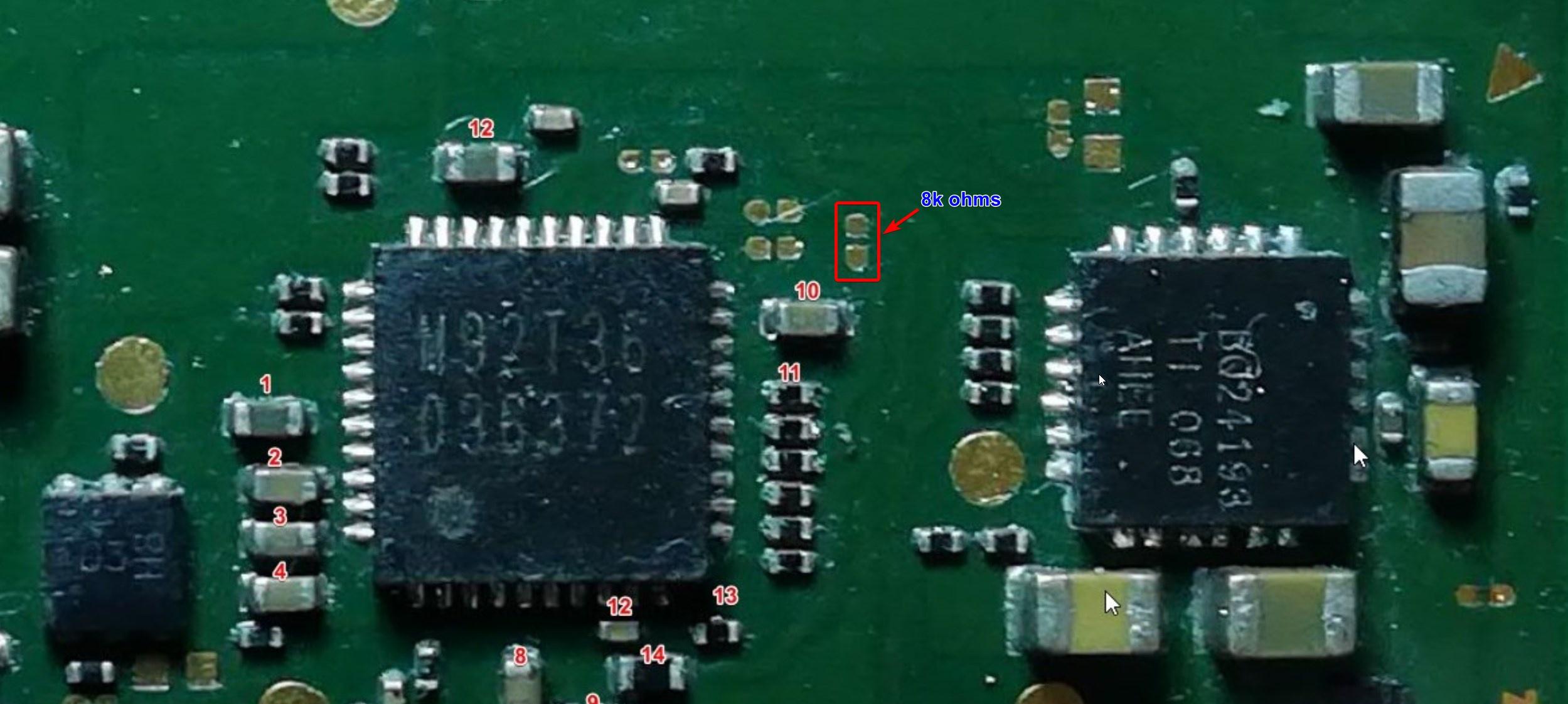
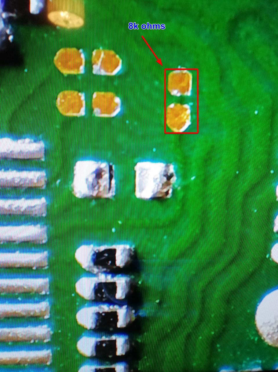
I removed the inductor the BQ IC and the M92 ic as well as that component that was chipped which I replaced and the value wasn’t increasing, I even removed number 10 component just in case it was bad but alas it still won’t go above 1.9k ohms infact with everything of now it’s 1.0*k ohms
Not sure if this helps or not but I get 8k ohms on these points as far as I can tell the line seems to go to the right side of number 10 component - but that right side shows 0.0 ohms and the left pad reads 1.9k ohms
So your reading on the SYS rail are concerning. you were getting the approximate correct readings earlier but since replacing that inductor by the 8316 IC your readings have changed, is it possible you knocked this IC (or the board) when up to reflow temps? as this IC is fed by the SYS rail.
What type of meter did you get? I would cross compare your readings so far between your old and new meter and see if they agree just so we can rule out meter issues here.
failing that, then pretty much everything else which is on this rail is in some sort of BGA style package and in order to pull and put these IC’s back on you will require solder paste and stencils and most importantly experience.
As this isn’t your board, I don’t know how viable the above options are.
 no more manual settings