I am hoping someone here with the vast knowledge on this forum can help me
I have a Nintendo switch which I bought as a spares one but thought id have a go at fixing it. It had a few midding resistors and capacitors around the m92 chip which I replaced. I also re soldered the M92, P13 and reflowed some of the voltage regulators.
I am getting no shorts on any of the usual places. I am getting 5v on the fuse, 4v / 3.3v / 1.8v on the testpads. The battery is charging at around 0.38 amps on a 5v charger and is near fully charged.
When I hold down the power button for around 15 seconds the amperage drops to around .22 fluctuating a little and as soon as I press the power button it jumps straight back up to around .38 amps again like its trying to turn on.
I have tried shining a torch on the screen and don’t see anything, when I touch the screen I get no sound. Plugged into a dock the amperage drops to around .11 - .18 amps and immediately jumps back up as soon as the hdmi cable is removed and back down as soon as its reinserted.
I am at a complete loss now after spending 2 nights trawling the forums for similar faults and taking several different measurements trying to fix it.
Any help / thoughts / things to try will be much appreciated as I am now out of ideas
I have tried connecting to 2 different laptops with a usba to usbc cable and it does not connect. I have tried variations of holding the volume up and power and both volume and power and makes no difference. Also not recognized in tegragui app. I dont know if it has been hacked in the past and have never done that myself but tried that path just in case
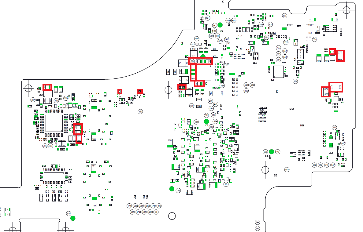
do you mean around the top middle chip in the picture surrounded by the red squares? I measured the coils around it not the capacitors marked by the red
I am getting 40 ohms on the 2 left ones, 1.1k ohms on the bottom left one and the top left climbs to over 1mega ohm, the top right jumps starts in the hundreds of kohms and drops down then starts going back up.
This is with no battery or power cable and no emmc connected, just the main board resistance to ground
Yup, that’s the one. I would say that mostly sou ds ok, though the top right one seems a little high, I would expect between 5 and 10k. Was that black or red probe on ground? Do you get anything different the other way round?
Hi, with black on ground it rises to nearly 3m ohm, when I switch it to red on ground it goes back down quickly to 1.1m ohms. Don’t understand the logic with that I’m afraid. Is there something that could be causing it to have such a high resistance?
Edit… Sorry that was top left. Top right acts the same both ways round, climbs to about 10k then jumps to about 800k then goes down again then climbs etc
I changed the m92 and p13 chips and still the same.
Tested and it does go to 15v and charges still.
Made an RCM jig and can get into RCM mode, then when I inject a payload the backlight comes on but nothing on the screen - not sure if the screen is ok or not though
I can access the memory card through TegraRCMGUI
I added files for Atmosphere to the SD Card on PC then put back in the switch. Then Injected fusee.bin and again the screen lights up, RCM gets disconnected but then the sd card is available on my pc by usb but still no display. I wanted to try this way thinking if it booted to Atmosphere then I could dock it to see if its working properly but nothing on the dock.
Backlight only comes on when payload is injected, not when turned on without RCM and only available as a drive on PC after injecting or in the tegra gui
I also bought a usbc board to test mu soldering on the port and all diode values are good. There is also continuity from the board to all the filters leading to the p13 chip, from the filters to the caps / from the caps to the chip.
Now im a bit stuck again, dont want to buy another screen unless I know the switch is ok and screen bad but cant tell that while it doesnt dock.
Is there anyway to just restore original firmware to the switch incase a mod screwed it up but without using the screen to do it?
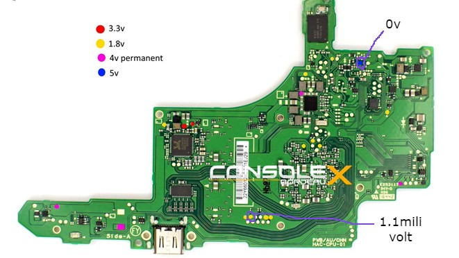
Well, that sounds like progress at least! In terms of software, I would see if you can dump this bis keys. You would need them for rebuilding the emmc, but I don’t know any more on that. LCD wise I would start by checking for damaged pins in the connector, they are so fragile. If that looks ok, check for issues in the area just to the left of the lcd connector. Thats where it gets its power from.
Check out this post when it comes to looking at the LCD power IC:
www tronicsfixforum com
/t/i-think-i-killed-it-short-on-lcd-connector-no-longer-boots/5729/10
It maybe the IC at fault but I’ve also had several cases where it’s the diodes which are bad and/or the resistors in the row just above, it may be benificial to measure in resistance across these diodes (in circuit diode mode readings do not help here in most cases) and compare to a known good
I’d also carefully inspect the LCD conn, it may well be a bent pin which initially caused the damage
Thanks Severence, Its a new LCD Connector I have installed onto the board and looks to be soldered correctly with no loose pins so will check the diodes. They look like they are soldered from underneath so cant access any pins to check in circuit so will have to remove with hot air to check. They are small though, does it matter with these which way round they go back on as with normal diodes?
Can I check the resistors in circuit?
There is also a cap in the row of resistors but its not shorted
If you take a close look at the PCB you can hopefully see which corresponding components those diodes are connecting to, if you can see it (could be a cap etc) try taking your readings from there which should save you the trouble of removing
Yeah, though the values may be somewhat different to out of circuit but if your comparing to another board then it’s not an issue, one thing to watch out for is resistors with damaged end-caps these can read fine from the top but not fom the bottom, in these instances your better off taking the reading from it’s next nearest connection or scratch back the mask if there isn’t another point availiable - this is only applcable in liquid damage situations though and the damage is typically visible, if all looks fine don’t worry about this
I’ve tried reflowing the chip, changed it for one from a donor but am not able to re-ball so tried with just solder on the board and chip but didn’t work. I’ve ordered a couple replacement chips to see if that will do it as everything else looks ok and I have enable. Hopefully be here mid next week to try it and fingers crossed that gets me a step closer