Any update here? I have the exact same issue ![]()
Hey folks. Sounds like you’ve got a few issues compounding this diagnosis. Have a look at the fuel cell IC as it’s famous for halting boot before backlight comes on. Its easy to crack with board mishandling and cheap to replace. I’d strike that off your list first.
Sheriff
Hi all, been busy with work and decorating so not tried anything recently.
I did try changing the Backlight driver when replacements arrived and don’t think I got it quite sat right as it smoked and now I have shorts in more places. Need to spend some time investigating further but worried I may have now shorted the CPU.
I will try looking at it again over the next few days and see if I can pinpoint the issue for sure and update this post.
Fingers crossed
Bit of an update…
I took the backlight ic off and the shorts are all gone so put a new one on again and still no shorts so thought great… but then when the usb c tester was plugged in it just kept flickering. I checked the M92 and no shorts but replaced it anyway with another I had off another board and got 15v, no current. Reflowed it and got 5v, no current. Took it off and back on again and the meter doesn’t turn on now so think its a faulty M92.
Going to order a new M92 and BQ chip to change them both and see if I get any further now the shorts are gone
Hey just to calrify, your talking about the 8316 IC next to the LCD connector right? backlight IC is elsewhere.
If your talking about the 8316 IC which you replaced, do you still get your 1.8V enable and in turn your +/- 5V rails being produced as a result at the points previously illustrated in the image? (Note, you will likely have to prompt the console to boot with the power button if the M92 IC is actually currently faulty in order to get any voltages here)
I’d check the USB fuse isn’t open just incase. If you suspect the M92 IC is bad, you can remove it entirely and if it was that which was at fault then the console should still boot without it with an error code, though you’ll have to prompt the console to boot with the power button instead of using USB
Sorry Severence, you are absolutely correct, I did mean the 8316 IC, not the backlight IC. I did check the USB fuse and that’s fine, I will try booting and checking for enable, also try without the M92 and report back
Thanks
No worries 
I’d also check your SYS rail prior, as it’s possible the previous 8316 failure has caused a fault here. You can do this by putting one of your probes on ground (screw hole pad is a good choice) and the other at any side of the 2R2 coil near BQ IC and letting me know the resistance
I checked resistance on 2R2 and got a moving figure from around 10k up to 900k
I replaced the M92 and BQ chip and have charging at 15v 0.48a but not fast charge but this is with a RavPower USB supply not original so don’t know if that’s the reason.
It did not boot but does go into RCM Mode. I am not sure to be honest if I have mixed up the Nand or not .
Injecting Biskeydump i got backlight but no display. Injecting Heckate.bin I got backlight then near the 8316ic a capacitor started smoking so I turned it off and disconnected the battery - see pic, the small cap in the middle
Before I go any further, please can you advise if there is a specific route I should take to diagnose?
Thanks again
I would start by replacing the capacitor. I would suspect that the 8316 is not on correctly.
That’s good ![]()
We can verify this once you’ve got the LCD shpwing a display using biskeydump (or other) though if you have mixed/matched the EMMC from another board there is a 50/50 chance you’ve blown the update fuse on the CPU which will require further steps later on
Can you highlight the capacitor in question so I can see which rail this is on? as afaict the small one in the middle would be VIN (SYS rail) which you previously didn’t measure a short on, I would measure the resistance across the capacitor and note the reading, if it’s shorted, remove the cap then measure across the pads and see if it’s cleared, though this will depend on the rail in question but provided the short is clear, then likely it’s not the IC at fault If it’s not short though, then as Insomniac said, it’s likely the IC at fault, and I would replace it with another.
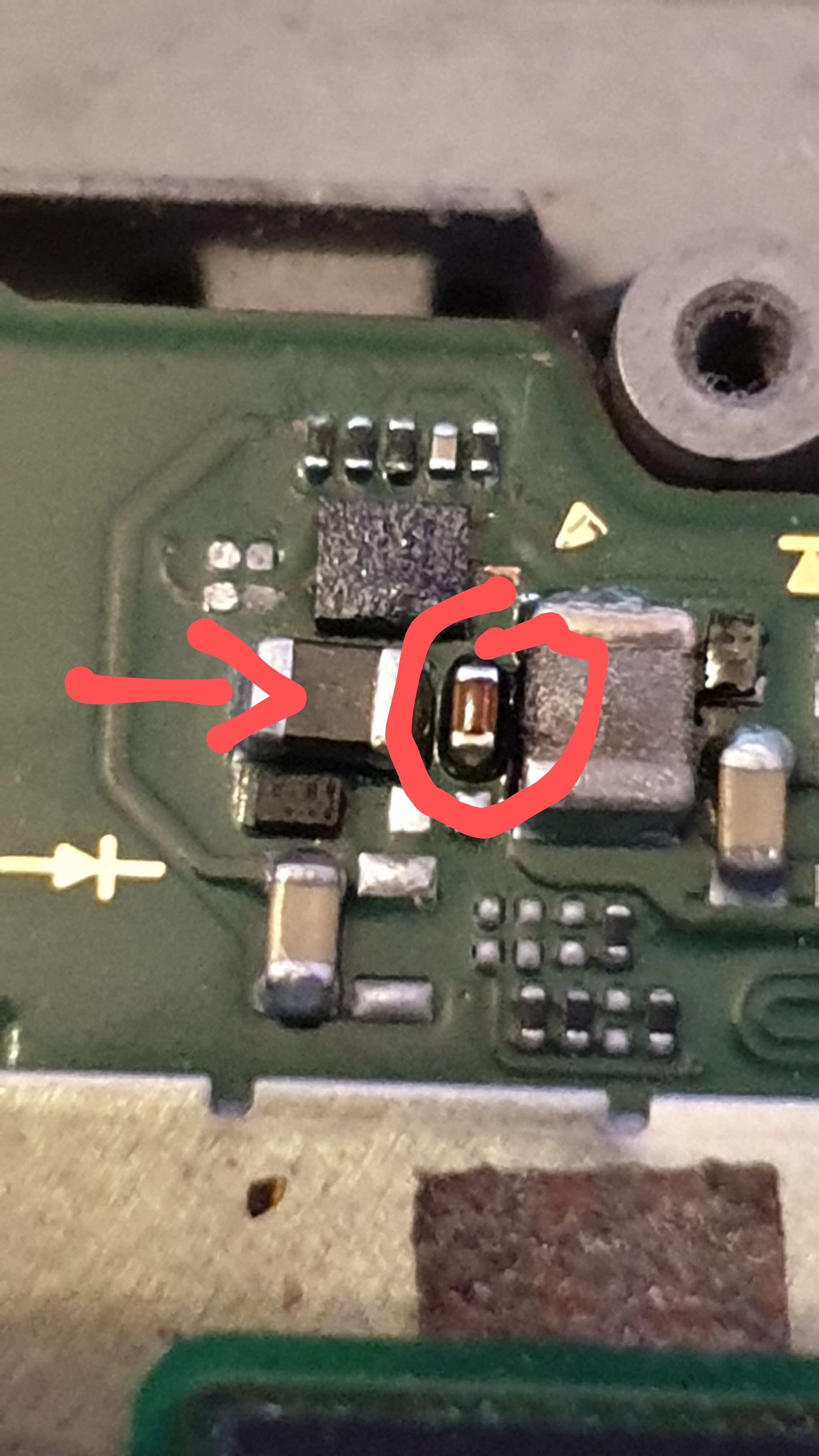
Without taking the capacitor off get 50ohms measuring from either side of it and no short to ground on one side - circled but the black component arrowed is now shorting to ground
Yeah, the highlighted cap is on the SYS rail which we already know is not shorted to ground, so it almost certainly is the IC at fault and/or an issue with your reball, though I would replace the capactor as a matter of course if it was getting hot
Think your meter/leads are playing silly buggers with your here, this is a bypass cap, one side is ground, so you should be measuring a near dead short here on one side of it.
helpful pic and measure from this post
Thanks @jkyoho
Checked measurements on this post against my board and mine doesn’t match, assuming 8316 IC not on right
On my board with Ram issue, the black component with he arrow pointing to it is OL both sides and gets 175k resistance to ground on both sides and diode reading of 540. on this board I get 5ohms resistance to ground and diode reading of 0v.
Also my other readings dont match the post by @jkyoho so it does look like I did not do a good job on the 8316 IC. Its a bugger as that is the 4th time I have tried that IC. Got 5 new pre-balled ones from RS Components and have 1 left. Was sure it was on right this time unless there could be something else causing them to blow each time? Would be nice to think I got it on right at least one time ![]()
Going to take it off again and recheck readings without it to see if they are back to normal before trying to put my last one back on
I haven’t checked, but that sounds about right, the black component is an inductor btw
Yeah, that’s no good, I’d pull the IC and see if that 5 ohm short to ground disappears
Ahh I didn’t realise you’d went through so many of them, I would verify the resistance to ground on the +/- 5V outputs at the 8316 IC when the chip is removed and also measure directly across those two diodes (using the nearest neighbour components/pads) in resistance to determine if they are shorted, while it’s possible a shorted diode could blow the 8316 IC it’s not actually that common but worth checking. The other possibility is bridges at the LCD connector pins/joints, I think you said you already verified this but worth double checking too
Most important thing is checking those above measurements prior to attaching battery/power to the board when you’ve put the replacment on, the chip won’t blow if you don’t power it up ![]()
@Severence Sound advice thank you, will give this all a go tonight if I get chance, if not tomorrow and report back, thanks again for all the replies, will not let this switch beat me lol. Only doing it for the fun and to see if I can, while improving my soldering and diagnosis skills so wouldn’t be a challenge if it was easy 
So took the IC off and get OL on most readings but assume that’s because the chip links the components and without it there is not path??
Resistance to ground on the +5v is 90kohm and -5v is 0.3kohm but that may be right as it links straight to ground if I’m not mistaken.
I am getting a normal reading now on the inductor but low diode reading of 0.134v drop on the +5v diode and OL both ways on the -5v diode - it doesn’t look very good. Resistance over the +5v one way is 6.5kom, the other way is 1.8kohm, the -5v diode is 295kohm both ways. Do you know what diodes these are or can be replaced with?
Seems a little high in one orientation, I measure approx 480 ohm across this in one polarity (though worth noting that the bare die versions of this diode which your board doesn’t use measure approx 4K in one polarity) and an effective fluctuating open in the other, perhaps meter differences at play here… what diode mode reading do you get across this diode in both polarities?
This diode has blown open by the sounds of it
I don’t tbh I usually just pull them off donors usually