It’s a 10k, it’s there on all of my boards.
The cap is 10uF from the BQ datasheet.
It’s a 10k, it’s there on all of my boards.
The cap is 10uF from the BQ datasheet.
I’ve googled BQ24193 and got the PDF file because there are some components around this IC that I’d like to replace because they look too dark or burned. They do work and don’t short around the IC though.
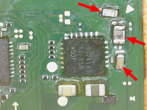
But as much as I’d like to extract some info on those components I highlighted from the image above, I just can’t. I see 47nF and 1uF but I can’t tell what size either capacitor is.
Also, instead of looking for each component individually, would you happen to know of a source for Nintendo Switch Lite components? I would go for a board replacement but over on Ebay, most of those items are on auction or just gone. There’s gotta be another place to look at.
Hello there @Severence! I’m glad you’re still watching this thread - you don’t have to but I really appreciate your help anyway down this rabbit hole, which seems to be getting more complicated. I just hope you also get to learn from this experience of mine. So let’s see:
Yes, I took this picture before removing the BQ IC chip. You can check the results:
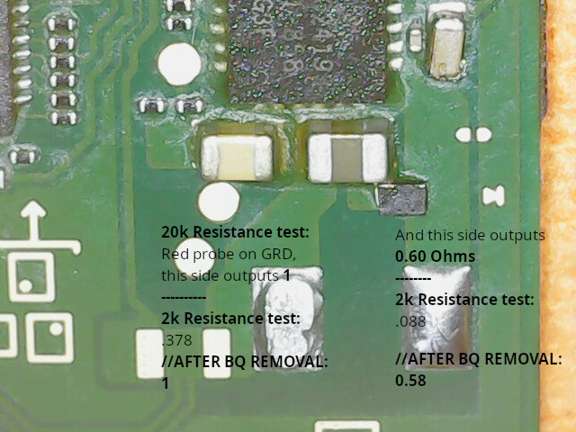
So in short (no pun intended), no changes after BQ is off the board. Should I solder it back before attempting something else in order to track down the short?
Keep in mind that both inductor and the BQ IC chips are off. I’ve got no idea where to go or what to do next.
Now that’d be a very interesting conversation, as I’d be on your level and merging my ideas with someone else’s always gets me excited! I gotta deal with this Switch Lite first tho it’s getting sad looking at the state of it. I hope I’m not dealing with a done-board.
@Severence Quick correction, those numbers under “AFTER BQ REMOVAL” were taken from a 2k resistance test. 20k outputs LEFT=1 and RIGHT=0.62 (Red probe on ground).
Ok,
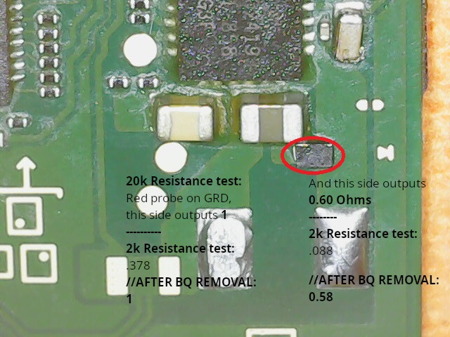
Let’s try to resolve one fault at a time, let’s start with the inductor pad on the right which is measuring 0.62 ohms relative to ground.
Now on an original Switch board, the right side pad of the inductor goes nowhere else other than to two pins/pads of the BQ IC, with the BQ IC removed on an original board there can be no possibility of it having a ground reference.
Now on you Lite board, it appears there is a diode present, this is the only difference i can see and is the only probable cause for the short this side of the inductor (path to ground) I would remove this diode as I suspect it’s faulty and then measure the resistance once again relative to ground on the right inductor pad and see if there is a change.
Diode highlighted
I would also remove those three capacitors you previously mentioned, the one with the missing endcap is likely to cause troubles in the future.
no, leave it off for the time being until we get to the bottom of these shorts, better to have less variables than more
That did it. I get 1 on the right pad of the inductor.
Yea that’s the question. I told @SheriffBuck even with the BQ schematics I couldn’t figure out what to make regarding the size of those capacitors. It mentions 10uF, 1uF, and 47nF but it doesn’t associate them to any working voltage or sizes and I’m afraid those details will play a major rule so I need some further info on those components. If I don’t need them for the time being in order to track down the short circuit, I’ll remove them right away. Moving forward, what’s next?
Does your meter display 1 if it’s out of range on the scale or something?
Only ask as 1 ohm can’t be possibe here with BQ, diode and inductor removed… you should be measuring OL (over limit/open cicuit) afaik.
The sizes can be determined by measuring the existing caps with a pair of calipers, the voltage rating can be determined by looking at the Max voltage present on this rail/line in the datasheet, as long as the replacement cap voltage is greater than that of what’s listed in the datasheet it is suitable.
In this case the cap with the missing endcap is on the SYS rail and the datasheet specifies a max voltage of 4.35V, as such, a capacitor that has a voltage greater than 4.35V is suitable.
Definately for the time being remove the capacitor with the missing end cap to take this out of the equation.
I think it shows 1 as in open circuit or over limit.
Never have I seen it output OL or OC in the display.
OK, that one is out.
Well if that’s the case, you might well have resolved your fault ![]()
Bit strange it shows 1 though, how do you tell the difference between OL and 1 ohm otherwise ![]()
So you might want to reinstall the BQ IC, afaict power and charging functionality should still work without this diode present.
As for the backlight driver IC, provided it is not damaged or suffering an internal fault you could use a stencil and solder paste or alternatively you could just buy a new chip which comes preballed.
but you should be able to monitor current draw without this backlight IC installed to confirm you have resolved the other fault.
Just add, after you’ve reinstalled the BQ IC, before plugging in the battery or charger, measure the resistance to ground on the Inductor again and ensure there is no short present (just in case the BQ IC had also gone bad)
It’s a no go. I tried my best to use the heat gun and solder the BQ chip back into place, it took me two attempts and I tested the caps around it, and none short to ground. After that, I resoldered the inductor to make sure I could power this thing back on and test the board with an ampmeter. Inductor is soldered but now I get 0A. I guess the struggle continues -_-’
What’s your resistance to ground on the Inductor now the BQ IC etc is in place?
Also, this is likely important
You can get away without the caps for testing but not the resistor
Jusr add,
That missing resistor of yours seems to lead to the REGEN pin of BQ, the resistor goes to TS1/2 afaict
From the datasheet, key part in bold
Temperature qualification voltage input #1. Connect a negative temperature coefficient thermistor.Program temperature window with a resistor divider from REGN to TS1 to GND.Charge suspends when either TS pin is out of range.Recommend 103AT-2 thermistor.TS1 and TS2 pins have to be shorted together in bq24193
I keep getting 1 on both sides.
Yea I thought so. Looks like another roadblock.
Isn’t there a way of testing just the BQ chip to make sure it’s sitting on its spot and I should worry about it no more? For example, if I test its satellite-components and they don’t short, could that serve as an indicator? What would you do to make sure all the legs are soldered?
Thank you for that. I will let you know when I get a hold of this component.
Which we’re going to assume is OL for the time being which is better than before. It should measure aprox 7K from memory relative to ground.
Would reccommend picking up a UT61E meter as it is a good budget meter and will rule out a lot of the cinfusion with your current meter.
Yeah you can run round with your meter in diode/resistance mode and compare the readings to another board which will give you a pretty good idea. Calvin has made a diode mode map of this area I’ll see if I can find it.
Well, it can give a rough idea that you haven’t bridged one of the pins/pads of the BQ to ground, but other than that, it doesn’t tell you if you’ve bridged two other pins not otherwise ground.
Thanks to @Calvin for this
btw are you sure this isn’t an “L” rather than a “1” indicating “Limit” perhaps… does it look different compared to when measuring a 1 ohm resistor?
It seems my meter showed 1. as in “You should use the correct RANGE thsi time”. And so I did. So I moved up from 20k to 2M Ohms and the left side of the Inductor reads .770 and the right side reads .782. I mean on the left side, value goes up - same with the right end of the inductor but after some time, each reading won’t go past those values.
That’s right, my meter doesn’t adjust the range automagically, I have to do it manually.
Question: Should each end of the inductor have the results I mentioned or just one? If the latter, it’d probably indicate there’s a solder bridge.
0.77M = 770K
I still think you meter is acting strange (would highly reccommend picking up an auto raging metere such as UT61E)
So either the BQ IC isn’t soldered properly, or, far more likely your meter is giving you a duff reading and it’s actually 7.7K (which is about the correct reading at this location)
Either way, this represents an open rather than a short which is fine.
Go round the pads around the BQ IC, put your meter in diode mode, put your red probe on ground and if any of the readings differ significantly from Calvin’s diagram lemme know. If all looks good though, then BQ is likely soldered fine.
I agree with the latter. Comparing my results against Calvin’s reference, there isn’t much of a difference. I also spotted two grounds around the BQ chip and those values are approximately the same, for more or less, within the margin of error.
I don’t want to connect the Switch Lite’s USB-C port to the meter, which is connected to a USB3 port to see how many Amps I get. I guess without that diode you pointed out to be removed previously, chances are some current can take the wrong way upon powering on the board and hit a source, am I right?
So what’s the next move?
Each end of the inductor gives pretty much THE SAME VALUE, is that right? Or was it supposed to be just one?
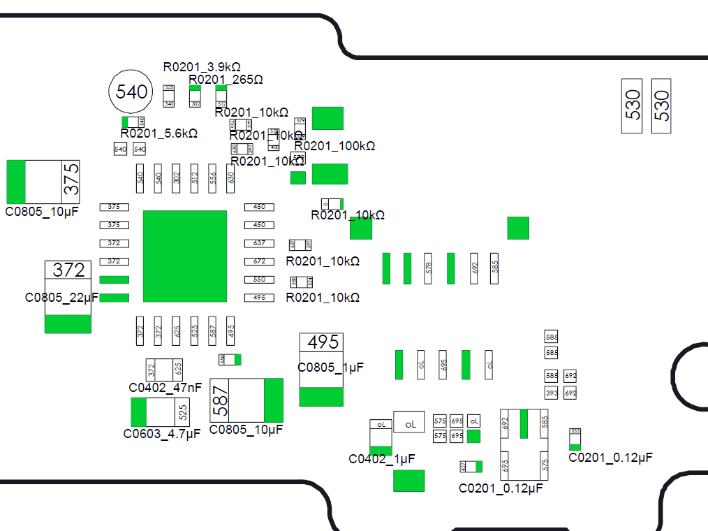
I’m going to stock those components placed around BQ IC.
@SheriffBuck these are the ones I’d like to replace:
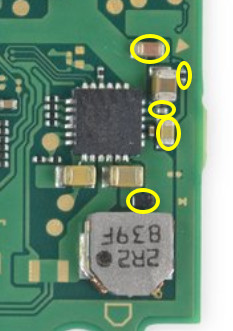
Some caps look burned and I accidentally blew away both components you mentioned (0201 10uF cap - by the way, should I go for 5V or 10V?) and the 0201 10k resistor.
Even worse is the diode which seems to be the culprit or the reason for the short; It’s between the inductor and the capacitor and I found no way to ID it. Because of that diode, I don’t feel like powering on this board anymore in order to check how many Amps I get.
I couldn’t agree more. The Switch LITE design looks more like a project that an intern decided to ditch because they thought it was too risky to materialize, for it would be such an easy-to-break design. A cable responsible for the transportation of at least 17V to feed the LED panel is folded twice, glued along the battery case and travels across to the daughterboard. And people think the regular Switch is hard. Try the Switch Lite, see how HARDER this gets.