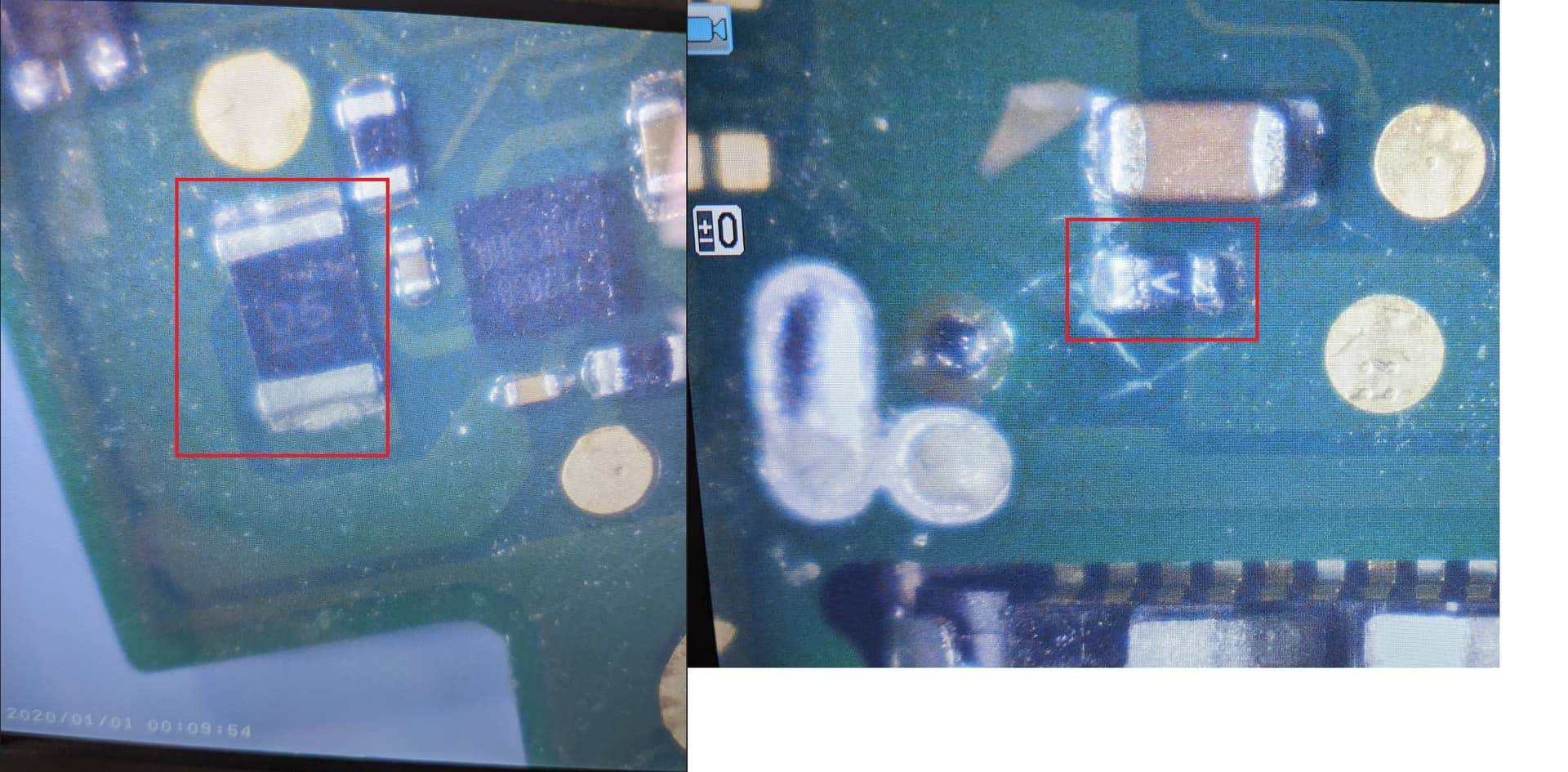
Well I have another switch lite on hand that is also demonstrating 15 v 0 amps. Switch boots and plays just fine with a charged battery. Is that SMD component with a V marking a fuse, and if so, is it the same on thats found on the full sized switch board (3.5A fast blow i believe)? This component has no continuity through it where it does on my “working” boards, bridging it with some tweezers and then doing a diode readings changes it from OL to .517 or so. My caveman logic here is telling me its a fuse, but id love if maybe someone with actual knowledge can confirm.
Also, the black SMD with the “05” marking (which is found on the far bottom left just adjacent to USB port), is this a fuse / bypass? Both sides short to ground and i get a .2 ohm reading in resistance mode. I’m getting similar readings on the good board as well, so I dont think there is an actual problem with it.
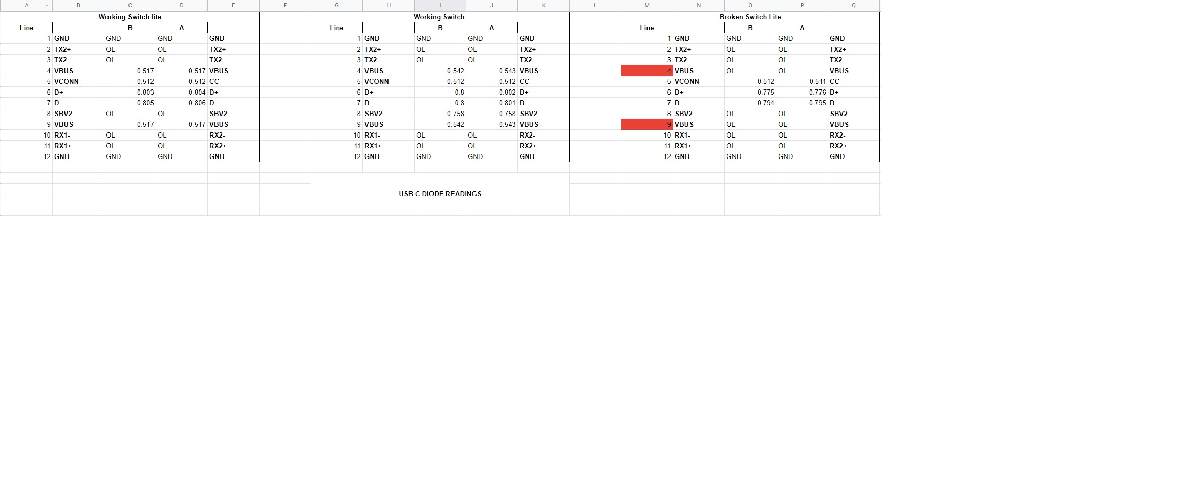
This leads to my final question, if indeed the first piece is a fuse then I’m left wondering exactly what could blow it? Are there any common culprits I can look at before I replace it? Generally fuses blow for a reason, but afaict there seems to be no issues elsewhere on the board. No shorting around m92 or bq chips, USB C breakout board does not show any lines shorted to one another, GND, or a voltage line. Besides the VBUS lines, diode readings on USB C seem fairly normal (im assuming SBV2 isn’t used on the lite, I get OL on both lites but .758 on the switch), and when chip is bridged diode readings for that line match my working boards.
I’m being a little overly cautious here as this board is absolutely pristine and the less work I have to do on it the better (still learning!) and would rather not risk frying BGA IC’s or anything that is irreplaceable. Thanks for any help!
Check your charge port inside pins if any bent, V code one is indeed a fuse, I would use 2.5A enough for it. 05 marking code one is 5 mil ohm current sense resistor. It goes to ground on one way, so short to ground is normal.
thanks man! Visual and meter inspection of the charge port was the first thing i did. All the pins seem normal and using my usb-c breakout board I didn’t detect any pins shorted to another. Double checked and made sure no lines were shorted to vbus either, so i think my usb port is good?
I’m just a little nervous because i dont want to replace the fuse, then have it either blow straight away or do permanent damage to a functional board with no work done to it. Already learned a 70$ lesson in playing too much with things so I’m just being overly cautious at the moment lol
I seem to have the worst luck with these things. Without me touching it, i went from getting 15v on the meter to only 5v now overnight. Just plugged it in to take the readings this morning and now I’m only getting 5v. System still boots and plays just fine though so i got that going for me.
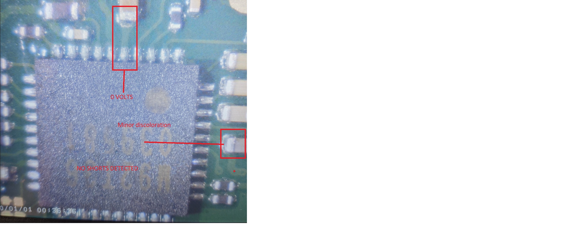
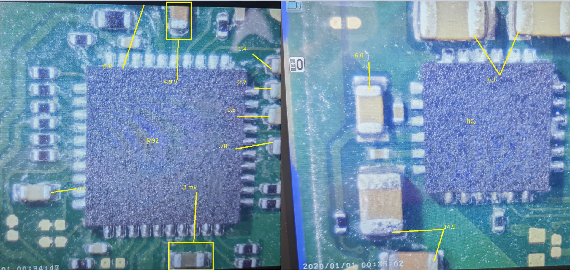
So M92 on what I’m pretty damn sure is VIN is showing 0v (i get some minor MV readings on this and all caps around the chip). As expected BQ chip is also showing the same, 0v everywhere.
Measuring the small test pad just above the USB C port shows 5v, get 5v on one side of the fuse but not the other (duh), but nothing seems to be making it to M92. I noticed some slight discoloration on one of the caps to the east of m92, and some slight discoloration on some caps surrounding a tiny BGA chip east of M92 as well (+ALJ chip, which has a large inductor right next to it and two 1206 caps right below). Still no shorts anywhere, just no juice. From all my research I am gathering M92 feeds
BQ so obviously if its not getting juice, then BQ wont either.
I know that fuse needs to be replaced but I;m assuming i still have a problem elsewhere that i need to find first. I’d really like to avoid frying things, but if I need to replace it to get a better test I can. Taking it real slow on this one lol.
Well, i went ahead and replaced the fuse, got 15v back on the meter again for one plug in test with no battery but then the fuse immediately blew again. I have a bunch on order now but I’m out of spares for the time being, still have no idea what could be causing it to pop. Diode readings on vbus before the plug in looked ok, still no shorts between lines on the USB C port as well.
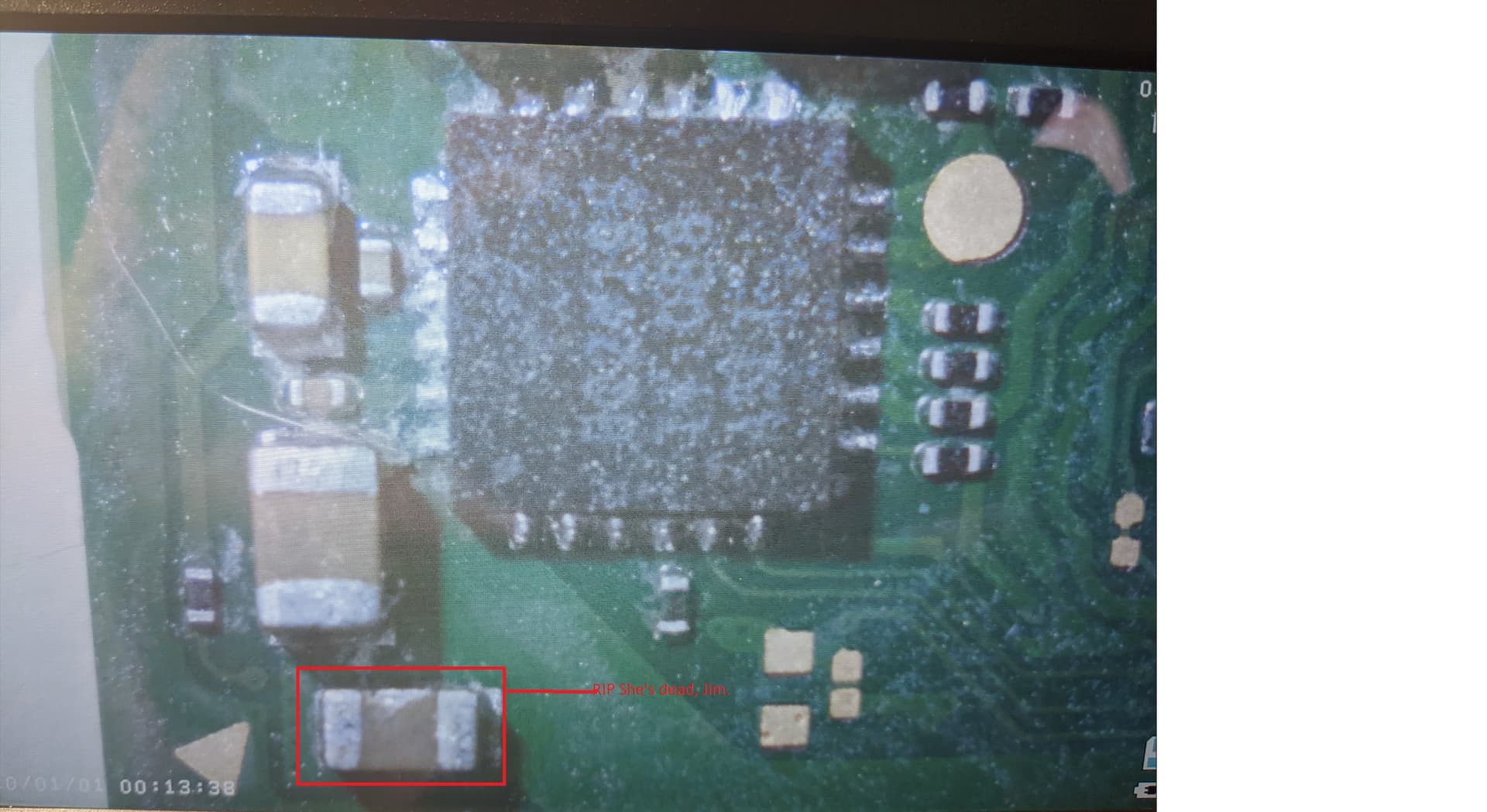
Well, had some rest and decided to keep probing. Discovered I had a short on the above cap now, pulled cap off board and short disappeared. Replaced cap with one from donor board and short is still gone. I am 99% sure i killed the cap after replacing the fuse and powering on so I really doubt this has anything to do with my root cause. Readings on everything else I poked out matched one of the boards I have with working charging. Starting to run out of ideas and I am now just waiting on new fuses anyhow before i can get ballsy enough to try powering on again.
Any idea on the value of this cap? I have a feeling im going to blow it again
Well, lucky days for me as I actually have a bunch of 1uf 0805’s from game gear rebuilds.
Hmm, so if this cap is the VIN for the BQ chip, im guessing this tells me the problem lies further upstream of it? Is the VIN fed from the m92 chip?
Sorry for so many stupid questions, I’m just trying to sort out how this all works together. Been spending hours reading up on the full sized switch since I can’t find too much on lite’s specifically. Seem to be pretty much the same circuits anyhow, well close enough to get a feel for things at least.
Pay attention to the cap voltage rate you have. Since switch pd charging uses 15v, if any less than that Voltage rate cap you use on BQ vin, slowly the cap become short again.
I believe m92t control the MOSFET from charge port above to feed Vbus to BQ
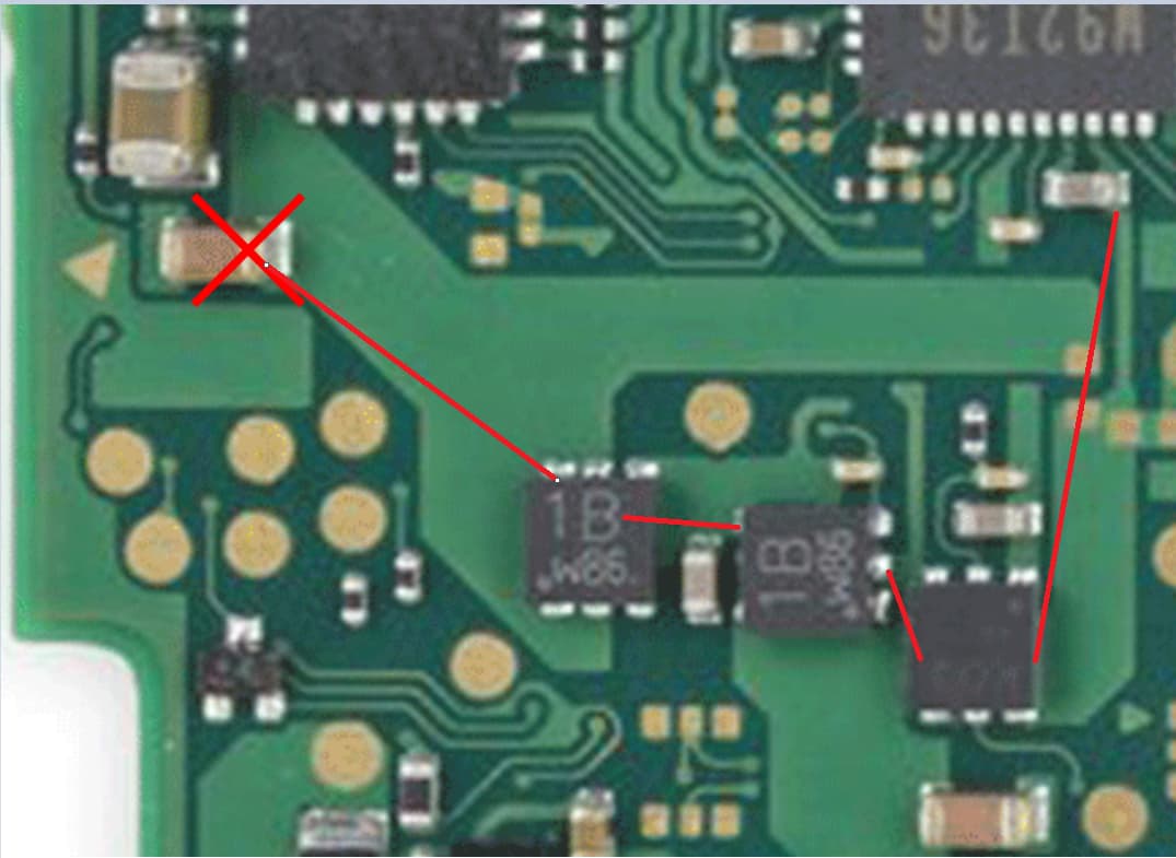
interesting. I’ve been trying to use the tool found at (http //balika011 hu / switch / lite/), little bit over my head but i think I’m catching on. I’m guessing this is the path from m92 to the cap then? Everything along this path showed appropriate resistance values from what I can tell. All the black chips were measuring mega ohms, and the caps fit in between them were all in the kilo ohm range.
I’m pretty sure with the blown fuse I’m not going to have luck reading voltages, correct? So I’m pretty much stuck until i get the fuse order in?\
You can temp replace the fuse with a chunk of solder joint and see if anything goes hot without battery connected(bare board with charger). Also ampmeter reading most case tells the story
I guess I’m just nervous bridging a blown fuse because I dont want to risk damaging an otherwise working board, if there isn’t a risk to frying the apu or anything serious though I guess I can give it a go.
It’s fairly safe diagnosis when battery unplugged, I think you mentioned the board still turns on, so pretty much your main issue sits between BQ&M92T36
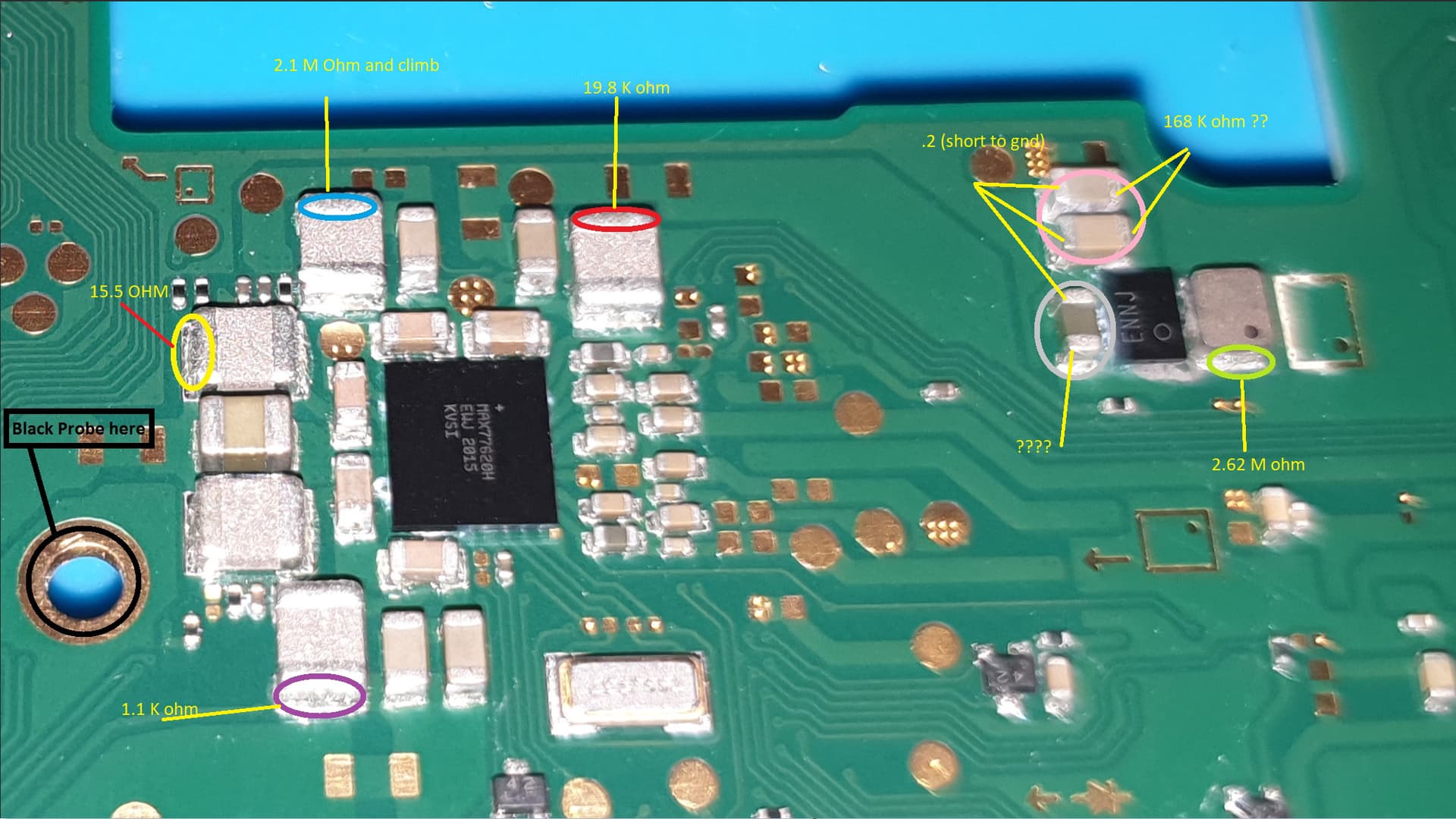
been doing a ton of reading and found a lot of helpful posts from @severance So i decided to go and test the stuff around the other PMIC’s using his diagram as an example.
On the blue marked cap, it starts around 2.1-2.2 Mohm but keeps climbing and doesnt seem to settle.
On the red marked cap, it ranges around a lot before finally settling around 19 Kohm.
On the pink marked caps it ranges around from 1 Mohm to 100 Kohm, then climbs up to the 167-168 Kohm range. It still noodles around by .1 every few seconds and doesnt ever seem to completely stabilize.
On the gray marked cap (with ???) i never get a solid reading. It jumps from Mohms to ohm to OL and back again, just absolutely nothing solid here
Ok, that gave me confidence to short the fuse and test voltages. I just tested all the caps around the IC’s, the inductor above BQ, and the test pad behind the battery connector.
Since it is not shown:
Inductor showed 4.2 v
Battery Test pad 4.1 v
Meter showed the 14.9 v and a .01 a current draw which eventually drops completely to 0. So if we are showing 4.1 volts at the battery test pad, can I conclude that most likely BQ IC is functional? Any other places I should look at in terms of voltage, and do readings on m92 and bq look ok?
A Bad M92 IC can blow a fuse and it may even be Bad if there are no near caps shorted
Interesting and very good to know. So I am guessing here that when i finally do get my fuses in, if I install and have made no other changes to the board we can really give the m92 a much harder look.
Resistance is not readable, jumps around and never settles at all
No short to ground, but i have continuity through the actual coil
Diode shows .112 with red lead on ground and black probe on coil (same reading both sides of coil)
Diode shows OL with black lead on ground and red prove on coil (same reading both sides of coil)