Hello,
I have a Nintendo Switch that went out overnight for no good reason. It is completely original and up to date.
I checked the load, it only takes 0.43A. The battery is at 3.9V.
I changed the M92T and the P13USB with no more success. I spotted a lot of capacitors on the shorted CPU (I have a photo but I am not allowed to add it to this topic, I do not know why.)
There is also a short circuit on the other side under the CPU. I removed the capacitors under the CPU and it doesn’t change anything.
I removed the connector just in case but no more results.
On the hardware side, I don’t have an oscilloscope but just a multimeter / hot air stations and soldering iron.
Is there any way to help me determine where the problem is coming from please?
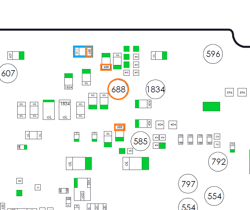
I would check in diode mode your „shorted“ caps to confirm that they are shorted. On the backside of the soc are several caps with low resistance to ground and are often mistaken as shorted. With red probe on ground and black probe at the lineside of the caps the reading should be something between 50 and 100 mV.
Hello,
Thank for your answer. I’m not sure about values. I do your trick and for example, one of the “shorted” cap have as value : .012V on a side an .000 at the other. Is it ok ?
I put back the P13 and the USB connector : 0.48A when i plug the charger but it doesn’t turning on.
Thank you !
Whats the resistance to ground on these “shorted” caps?
IMO it’s pointless taking diode mode measurments on these rails… you could have a 10 ohm short to ground and still get “good” diode readings depending on the meter etc… which we’ve seen countless times before on thi forum and much chasing tails until taking a proper resistance measurment.
Hello,
The resistance to ground is 0.000. I don’t think they are shorted finaly no ? If i understand, they must have a 0 resistance to ground and a resistance on the other side , is it right? Thank
Thank you.
Ok so what is meaning ? If the value is too small, the caps are shorted or not necessary ?
I’ll check the value with your image but it’s impossible to read values on little caps. Do you have it please?
Thanks again
Little update : With all your replies (thank again), i find some bad solder and one capacitor faulty.
Now i have “only” one problem : 5V line is missing. I have the 3V, 1.8V, 4V but not 5V.
Maybe you have an idea for this please?
Thank you
Maybe you should read the postings before you post your personal opinions.
Tiripstruk mentioned shorted caps on the backside of the soc. And like I wrote, there are caps which are over and over mistaken as shorted. To confirm that there are or are not shorted, he should compare his measurements to the ones on the map. And even with an offset due to an other multimeter, he should be able to see if his measurements corresponds to the written values.
Even you are obvious no friend of diode mode reading, the diode map is for me a very good posibilty to see if there are missmatches or not and mostly pinpoint the problems.
Besides this, I don t have to pet someone and hold his hand for every single resistance measurement to confirm it is ok or not, because it is already measured and written down. Or am I missing something?
If you can measure two different values on the both side of a cap, the cap is not shorted.
Where did you measure the 0.012 V?
I did of course, just because somebody says something is “shorted” doesn’t make it a dead short, most meters in continuity or diode will buzz on such a low impedence rail and for a lot of people they will consider it a short.
And again it was merely my opinion…
As I’ve said many times dude, your diagrams are awesome, I didn’t mean any offence and my comment was not pointed at you, it was merely to point out typical traps which can lead to wild goose chases.
Not at all, diode mode has plenty of uses, it’s great for testing diodes for one
It is kind of strange, if I give the advice ‘please measure the mentioned caps and compare it’ and you state ‘it is pointless’.
The lowest caps on the back of the soc have 70 and 90 mV and if he can measure something around this, there is no short and the assumption that the caps are shorted is false. If he can measure something else standing out lower there might be a problem.
I got the point, that beneath a low value in diode mode the meter will also start to buzz. But if I know I m testing a low resistance point that can be mistaken in continuity mode, I m looking at the values. Or does other multimeter cuts off?
Yeah some meters can do. Also the forward voltage between meter brands can be wildly different, and these low impedence rails can show drastically different diode mode readings as a result, which is why I said it’s pointless on this rail.
The other reason, as I mentioned above, if there was an actual short on this rail, then the typical failure mode is typically “high” ohms short to ground, not a dead short, so an 8 ohm short or a 20 ohm short to ground, in such cases it’s highly likely that depending on the meter you would get a “good” diode mode reading (dependent on the meter), you’d move on not realising the actual fault.
In contrast, while resistance mode can vary from one meter to the next due to the differences in forward voltage etc it’s generally more consistent
Ok, good to know.
I made the diode mode map with a UT61E. And till now I hadn t have problems with other diode mode maps which where for example made by a Fluke 17B.
So I have this value on the “positive” terminal of the capacitor and 0 on the negative.
I will read all the answers and follow the advice to see what happens.
I know that it is difficult for regulars with a very good knowledge of electronics to help newbies, I am sorry that I do not have great knowledge and I try to learn and progress continuously.
Thank you to you for the time spent anyway.
Sincerely,
Jonathan
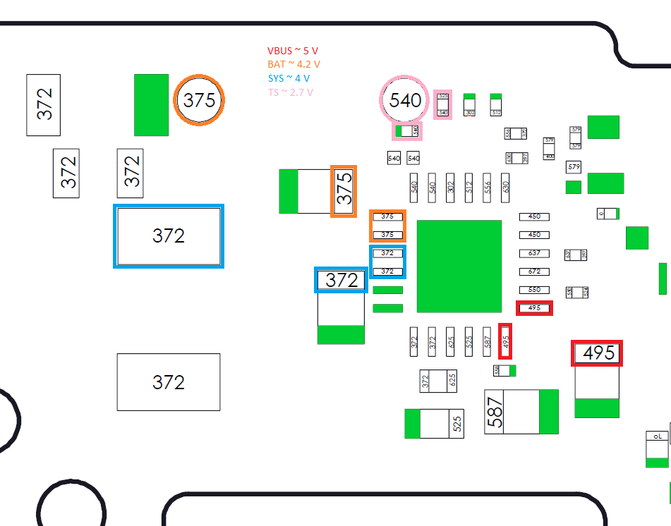
No no, I took the diagram of tension control which is on the forum. It is indicated the different voltages which is on the motherboard. So I have all the voltages that seem to be present except the 5V.
Small return:
I checked the diode and no worries, it is not burnt.
I checked the capacitors and they don’t seem to be a problem either.
Is it possible to control the 5V line at the output of the M92T? I changed it and suddenly I have a doubt about it …
Maybe it makes sense to eliminate this component first?
Thanks again !
What is your reading (diode mode and resistance) at the 5V line?
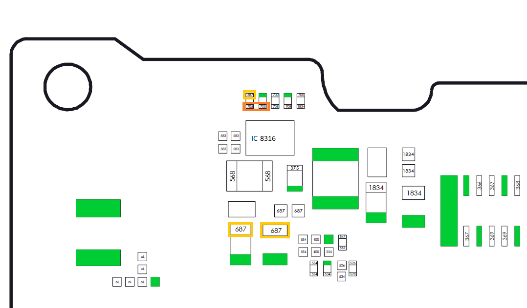
If I m right, the 5V for the lcd is generated in the ‘8316’ ic. This ic is powered by the sys-line and not by the m92t36. The bq24193 manages the power for this line. From battery or usb-c.
SYS seems to be present , i have the ~4V. I’m not sure if it’s normal but i find 15V on 5V points.
I check the TS , value is ok.
In diode mode, i find “.785” on 5V point.