Another board, another problem.
Beep no light
They reworked the HDMI port.
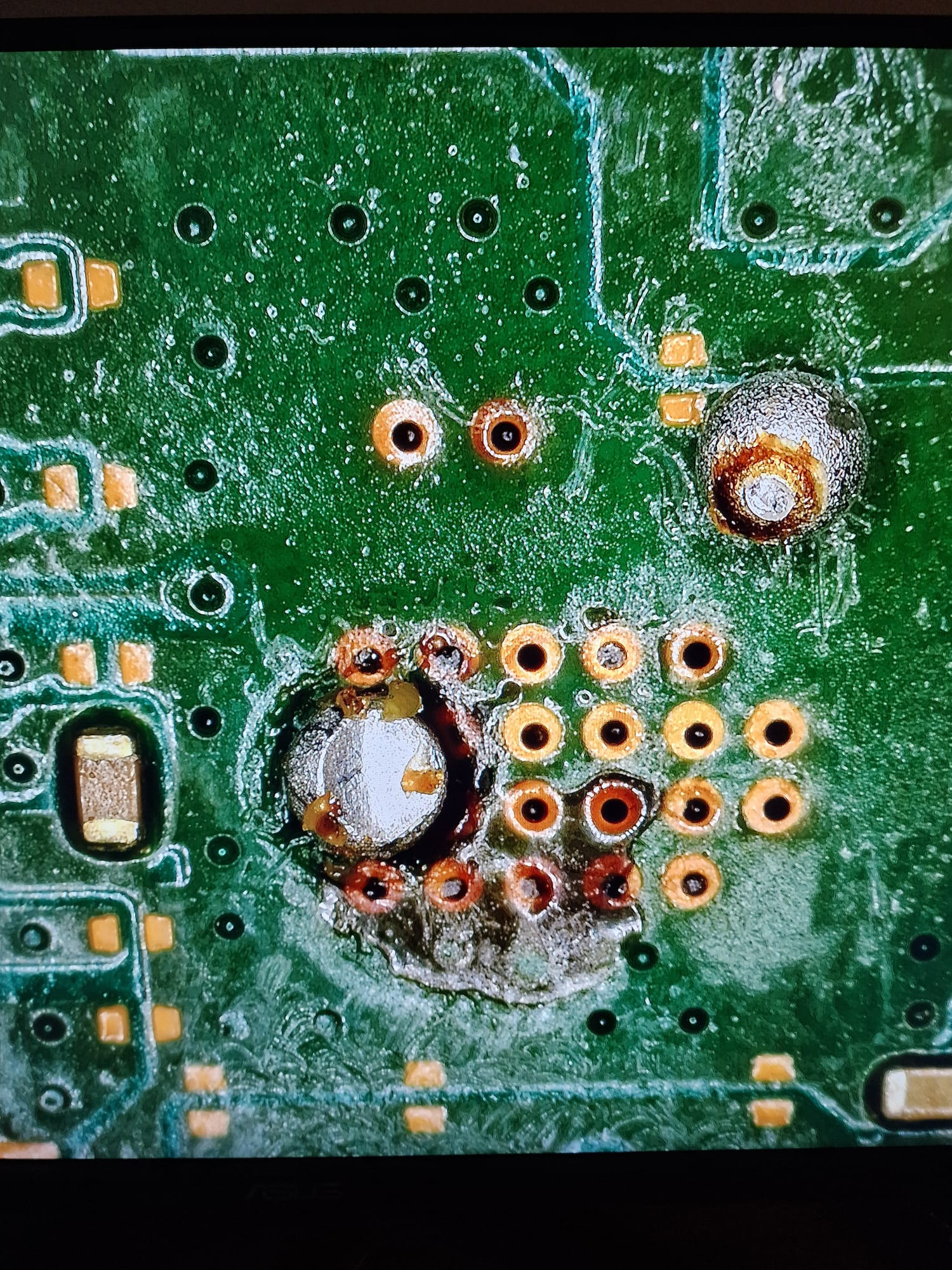
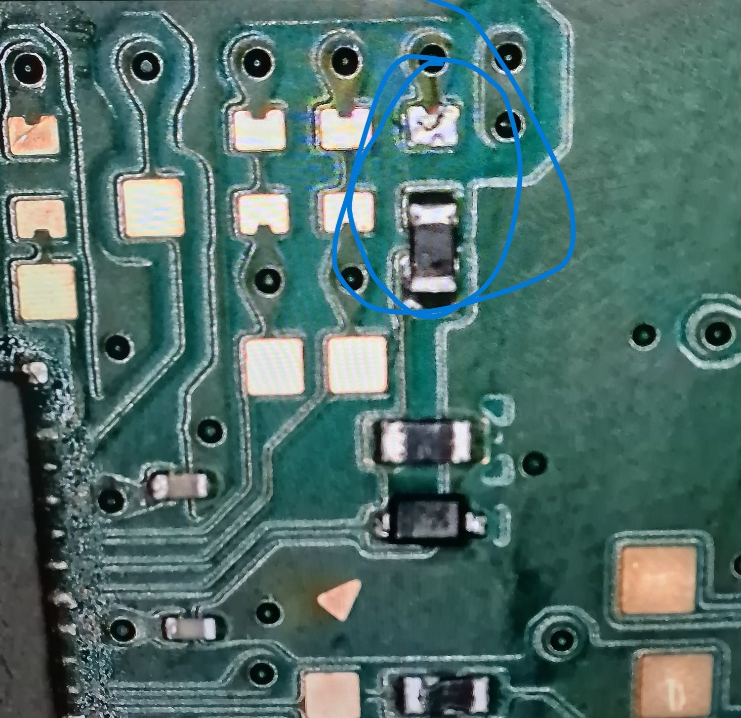
There’s damage in the area shown in the photo.
I removed the solder and the mask appears to be damaged (perhaps a spot with no traces?)
The port pins don’t appear to be shorted.
The capacitor is damaged but it reads voltage.
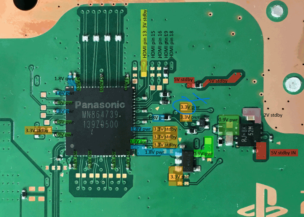
HDMI Pin 13 measures 2.91V, as does the capacitor underneath.
What values should the diode and capacitors have?
Missing:
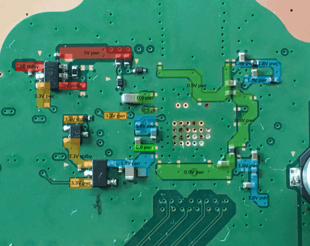
5V POWER Photo 1
Other all good
The readings on the Panasonic STBY and PWR One are all correct (I can’t read them completely because the board immediately collapses, but they are all present)
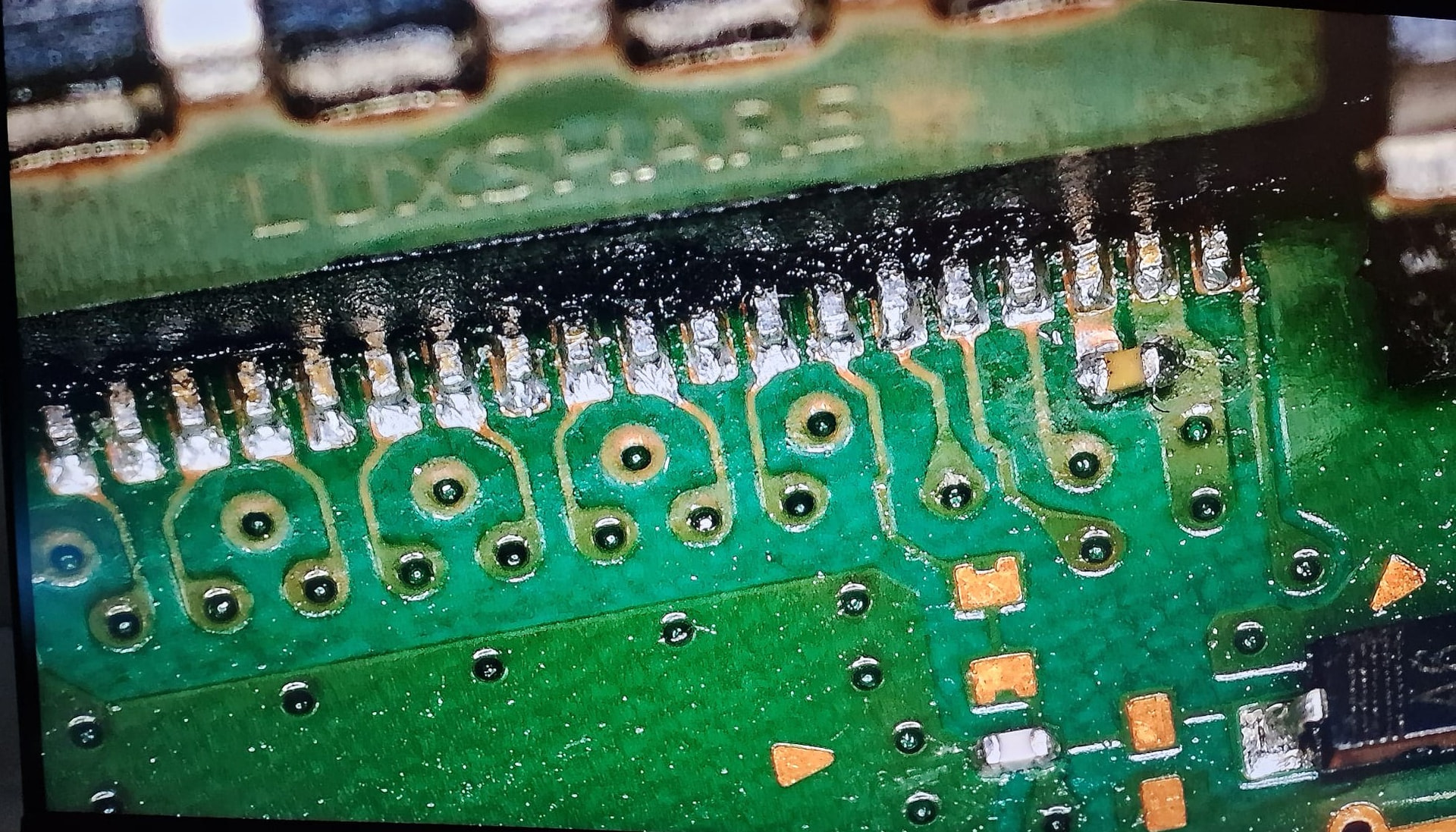
Removed HDMI port and cleaned the bridges.
The boot sequence is now correct.
UART shows no errors in standby, but always the same ones in power on.
5V Power on is always missing.
If the pwr lines are not shorted, I would inject 3.3V at each enable line for all four bug chips including the “RJ=” ic and check if each output is present. If all power lines are present, I would replace the HDMI chip.
I did an interesting test before removing the SB.
I injected 3.3V into pin 3 Enable, and PIN 6 shows 5.15V.
I tried turning it on…nothing…blod for 1 second.
In theory, it should turn on…R7 SB pad it only goes to that IC
Maybe I should investigate further?
Can the diode/retimer pull the line down?
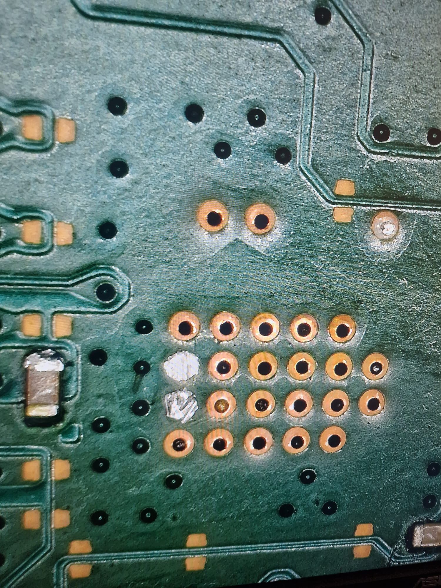
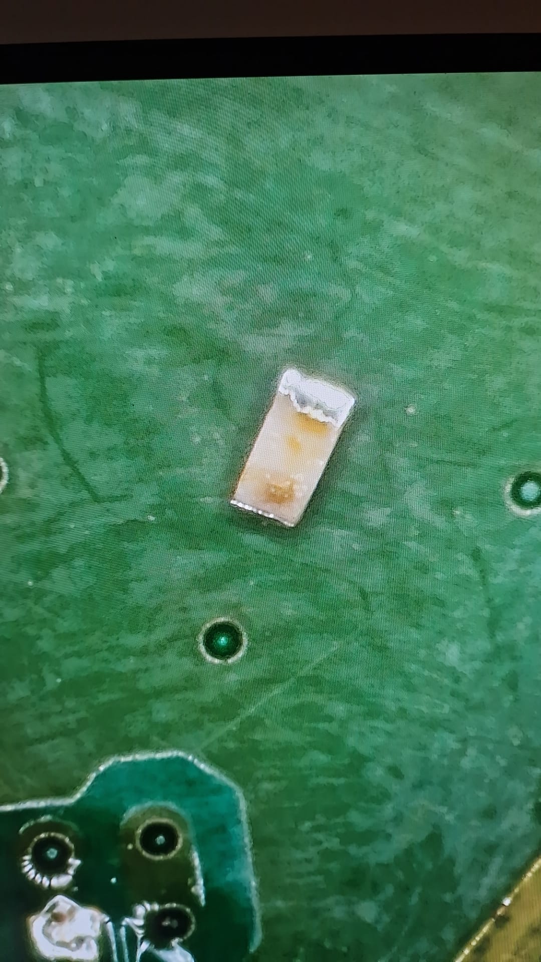
Sorry, the photo didn’t upload.
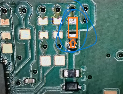
It was placed on the test pad, and I removed it, but it seems damaged.
Do you think I might have knocked the line down? There’s another resistor and a diode underneath.
Pin 35 Panasonic = HDP = Pin 19 HDMI Port
If there is still 22 Ohm at the resistor you desolder, I would put it back in the correct position and check if your start issue is solved. There seems to be on both ends of the resistor enough material to connect it to the pads.
The other resistor is a 6.8k Ohm and the diode is a Zener diode. As long the line is not shorted to ground, I would expect for the first try with the 22 Ohm resistor soldered back in right place, that the function should be back.
You can check at the HDMI port at pin 19 for correct readings. (6.8k Ohm/700mV)