After attempting and giving up on the 3 in 1 install, I tried the previous V1 and 2 Picofly version where the EMMC plugs into the Picofly directly.
The problem is that the EMMC gets extremely hot very quickly and nothing comes on the screen. I believe I might have damaged it as it was also overheating during the 3 in 1 install.
I removed as much solder as I can from it and cleaned it up but no difference.
The EMMC chip also gets hot when it is plugged directly into its old stock Nintendo socket instead of going through the Picofly.
Could someone please help me work out what is going on?
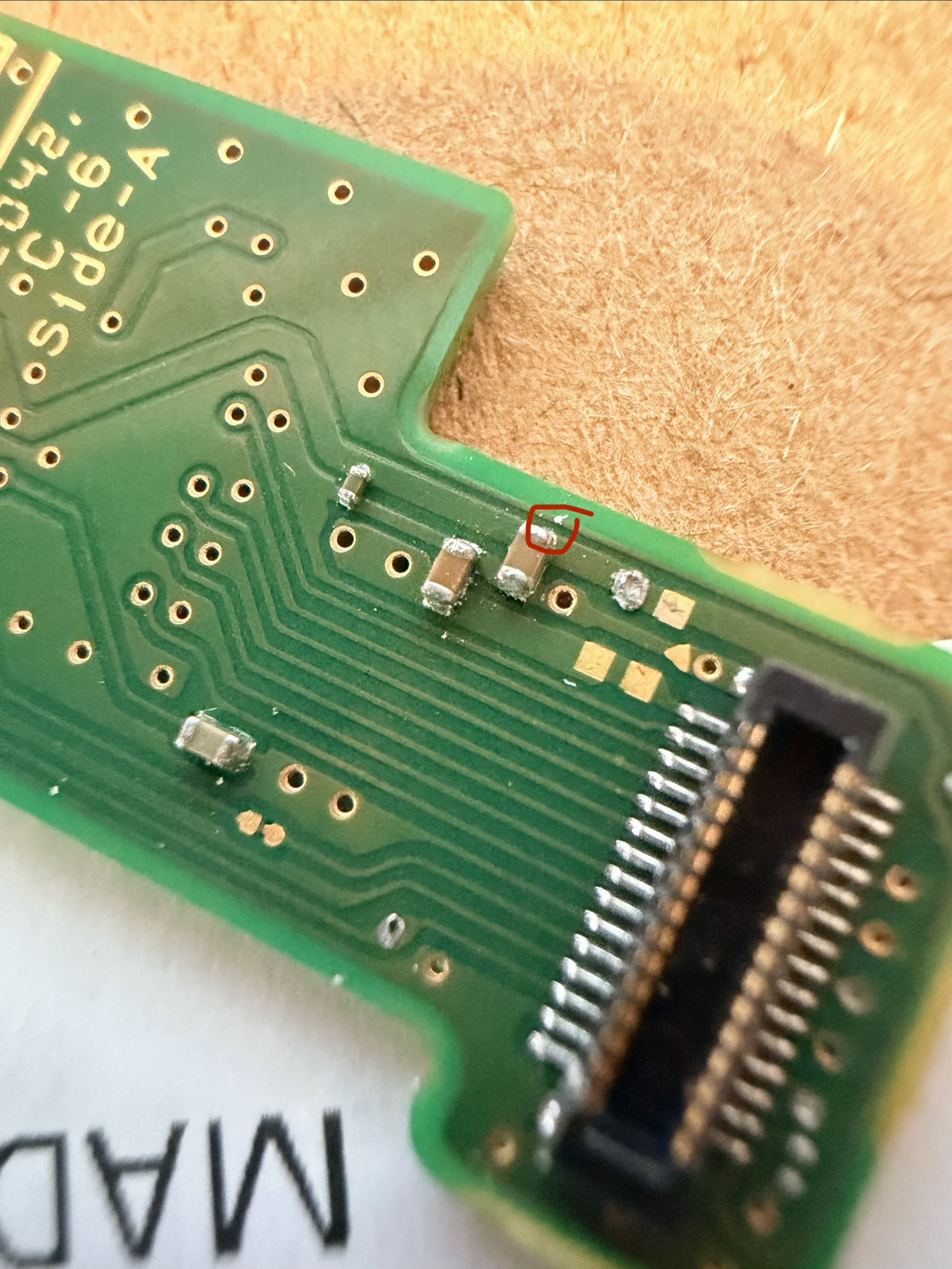
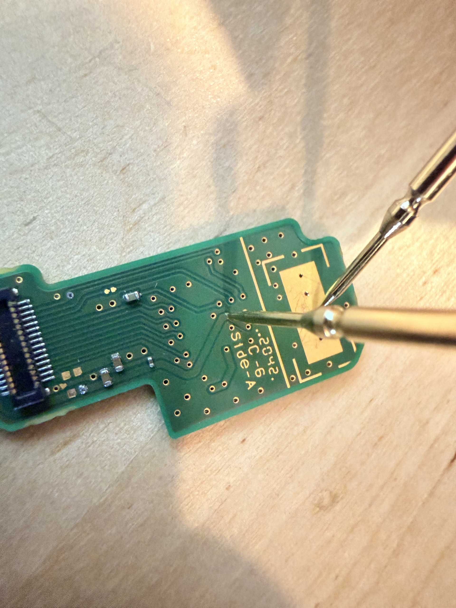
I’ll adid some pics of the EMMC board and the Picofly. I presume if I can’t work it out the switch is toast?
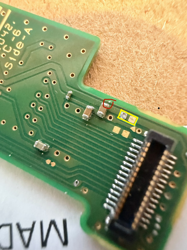
There was a cap between these 2 points, but it came off might this be the cause? I think I read that these caps are not 100% required but I might be wrong. Thanks so much for helping!
thank you, I tested the output on the actual switch board connector without the EMMC, it looks like it is supplying the right voltages. Also the Values for sp1 and sp2 seem good.
My tiny probes arrived and I’m trying to get use to them! I’m getting some reading but don’t trust the actual numbers.
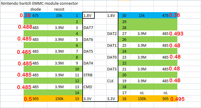
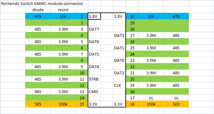
One thing I did notice, when the multimeter is on diode testing mode, 15 and 16 on your diagram do not beep and show OL. I tried to test this he resistance and got amount 2.5 M ohms.
Hi! I saw a video about someone fixing a short on their EMMC board (_youtu.be/7dUlJh8SlWw?is=7tDgqAeupOYY6RTy) and I looked at the cap he tests at 8:39.
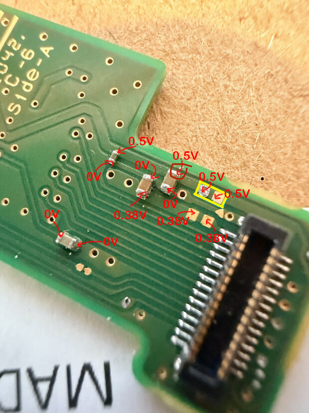
If I do diode mode and test one end of this cap against ground , it ends up at OL. Might that be an issue? I used diode mode on that cap and it says 0.5. Looks like he just took the cap off?!
Ok I think the super fine tips are messing me up. I’m sorry, I think I misread the end of that cap.
If I put the black probe on ground and red the probe on the yellow and red circled points I am getting around 1.5 volts in diode mode. There is no beep on those points when measured. If I follow the trace back, it’s the same value with no beep (see pic).
Perhaps we are also at the point where I should be looking into a new Switch. It seems that the fix to whatever is wrong is something that would require a person with actual skills and a hot air setup (definitely not me!). I have learned a lot though.

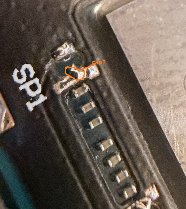
 might this be the cause? I think I read that these caps are not 100% required but I might be wrong. Thanks so much for helping!