Hello, I need your help because I don’t know how to troubleshoot.
I have an error code on a Nintendo Switch, the charging connector pins were damaged but none were touching and a short on 2 components above the M92 chip.
I changed the USB connector and the M92 chip and I no longer have a short circuit on M92.
I no longer have an error code and the console no longer starts, I have another short circuit next to the 8316 0759 chip next to the screen connector, this component beeps on both sides.
I wanted to post photos of my work but I can’t because I’m young and registered on the forum.
The fuse after the USB connector is ok.
15v comes to the M92 chip
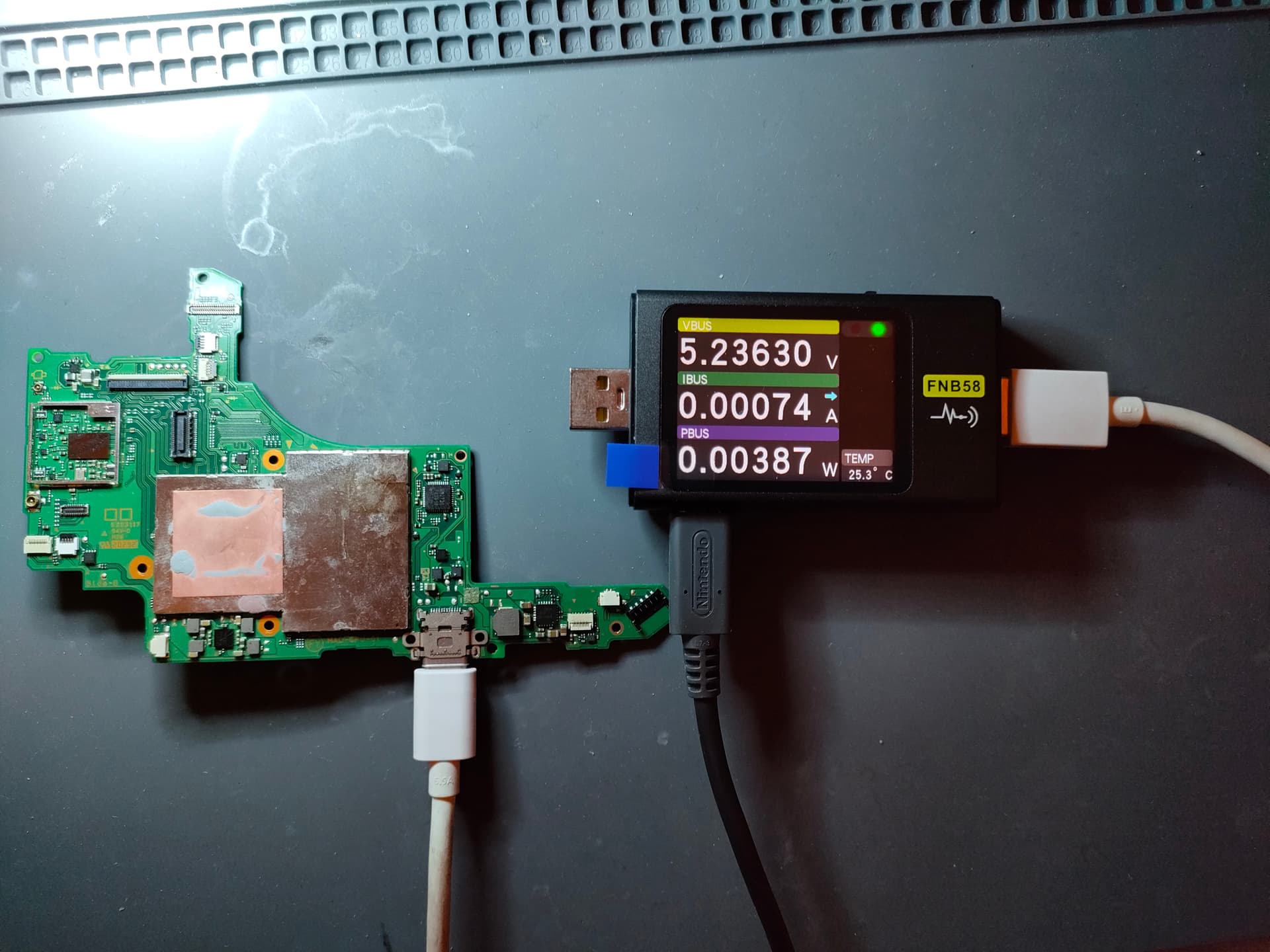
The motherboard connected to the charger gives 5.23603 V 0.00074 A and 0.00387 W
I have the hardware but just used to changing the parts of the smartphone and soldering usb connector and non-complex component,
can you guide me to find the problem?
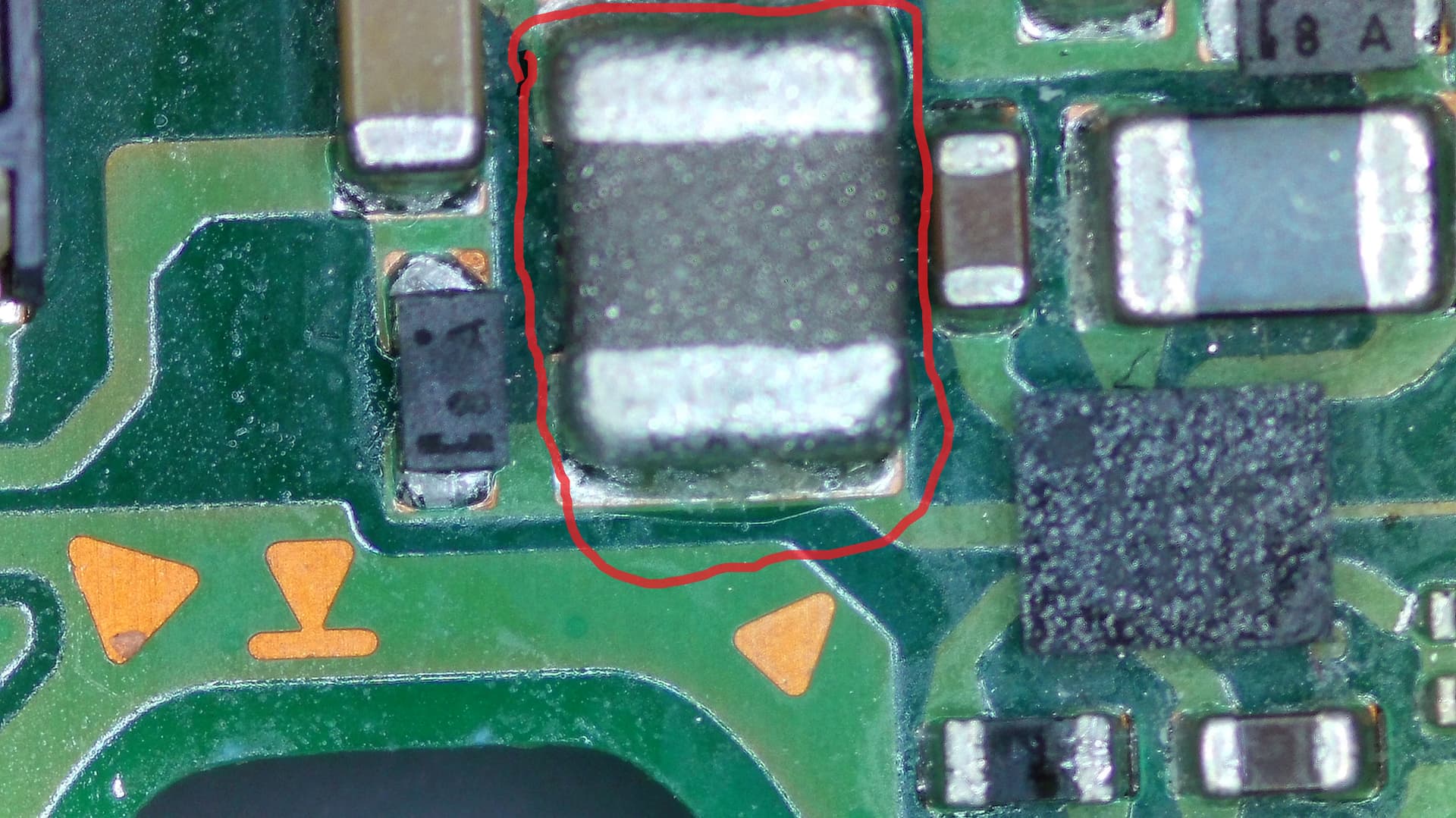
The large inductor near the 8316 always has ground on both ends and it is likely fine.
I’d go over your port and m92 installations since those are the only things you’ve changed since it was booting prior, also there is a chance the m92 is fake or bad if it came from somewhere like aliexpress
Upload some images of the m92 and port replacements and share the link
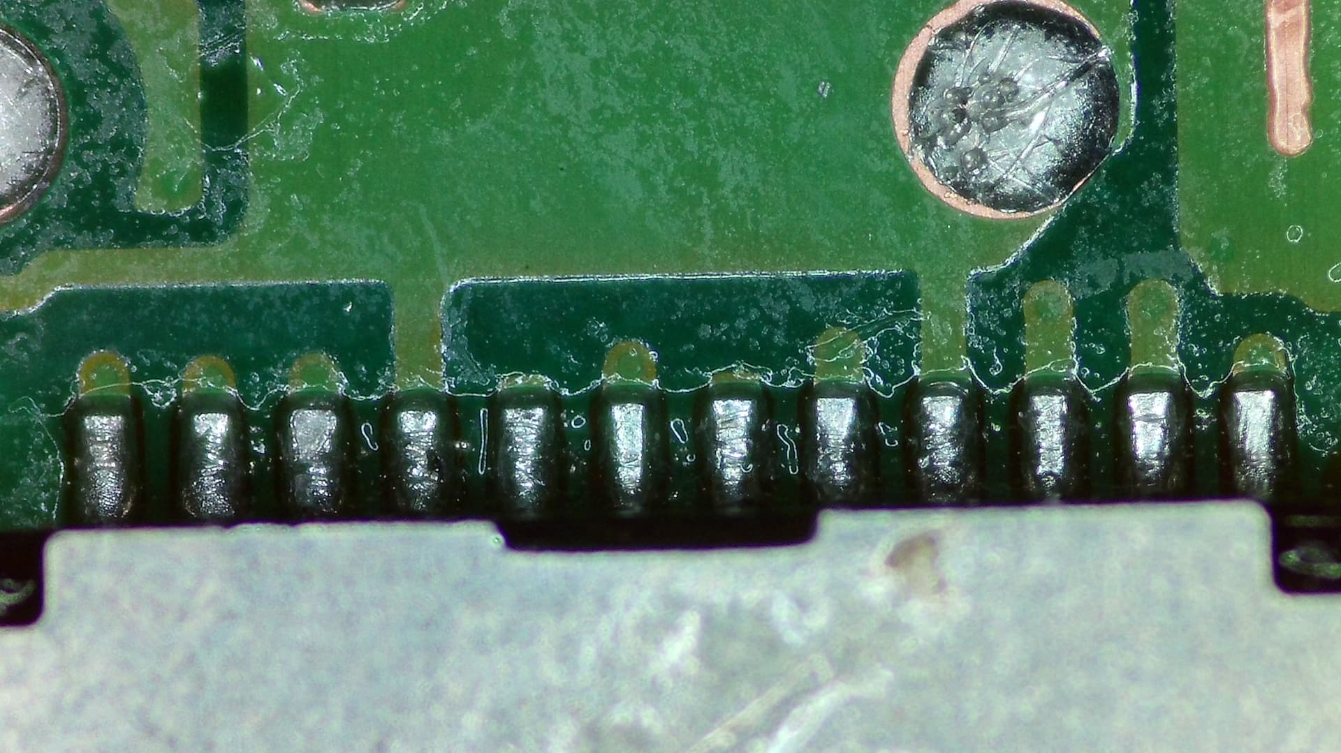
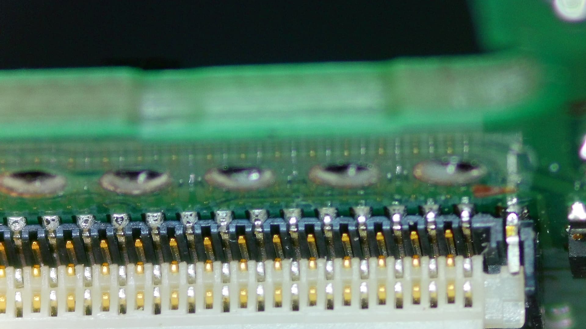
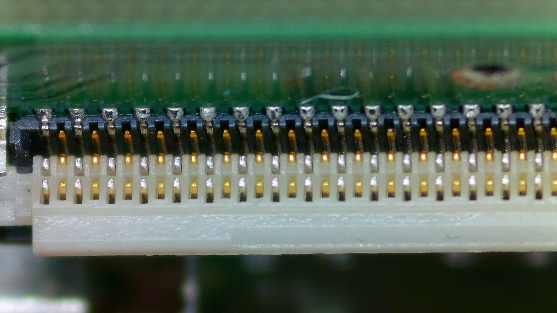
Here is an image of the large inductor near 8316 to confirm that we are indeed talking about him.
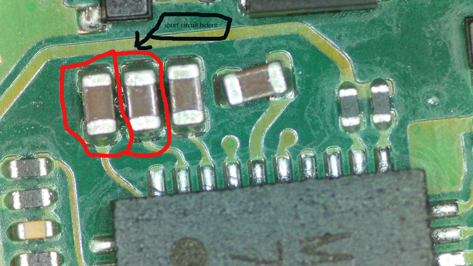
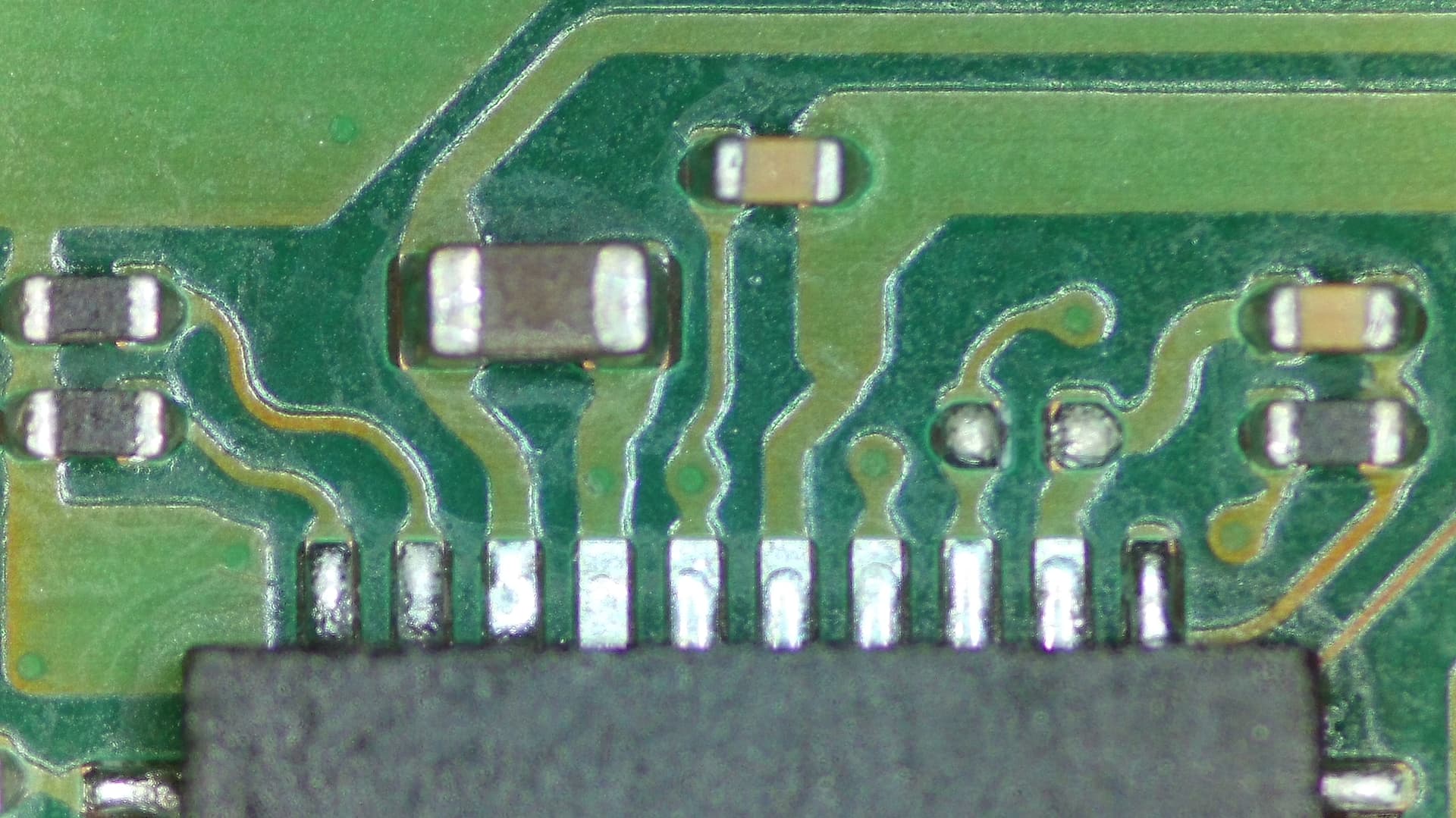
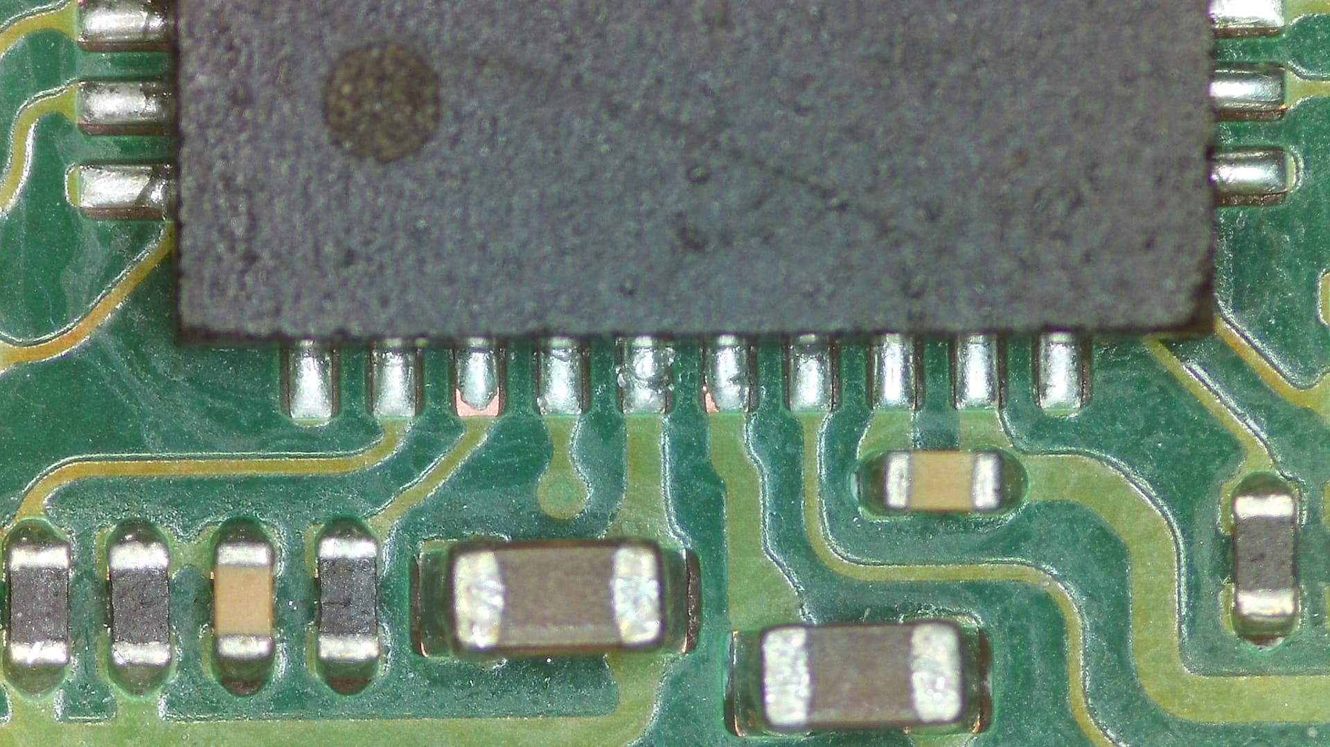
Some images of the M92 and the USB connector, the 2 components circled in red were short circuited before but not anymore.
An image of the values of the motherboard plugged into the charger
Thanking you for your help.
Yes that is the 8316 inductor that has ground on both ends.
Your m92 install looks fine, your next step is to go over each pad on the m92 and make sure you get expected values, try to probe the end of the pad rather than touching the m92 ic it self, there could be a connection issue.
Have you checked for the various voltage rails while the board is powered?
Check the same rails for dead shorts before powering the board
rails to check and what voltage to expect;
0v8 CPU → ~0.95v, may be slightly different with your v2 board
0v8 GPU → None, this rail gets enabled later on in the boot cycle
1v1 → 1.1v
1v8 → 1.8v
1v15 → 1.15v
1v35 → 1.3v
3v3 → 3.3v
5v → None when using official charger
Sys → 4.2v

Firstly, I will give you my unpowered motherboard values. I would indicate “yes” for a positive continuity test and “no” for negative followed by the ohm value. To be sure of my values, for example on the 3v3 rail, I set my multimeter to 20k, the black wire on the USB connector and the red on the point indicated on the image of the motherboard, for the 1v35 rail on 20M, for 1v15, 1v1 and ov8 I have a doubt, should I set it to 200?
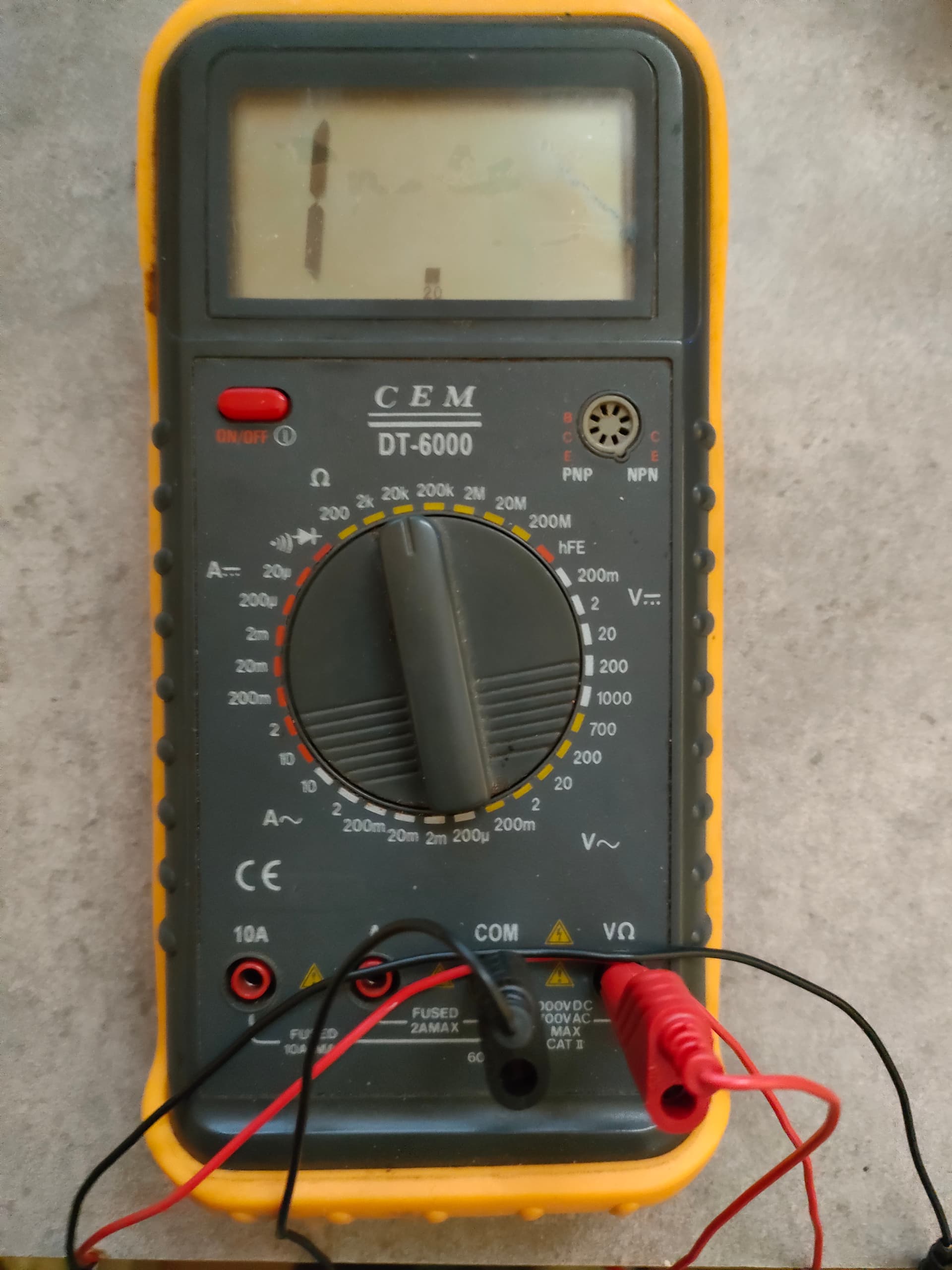
Firstly I give you my values for the motherboard not powered, I would indicate “yes” for a positive continuity test
and “no” for negative followed by the ohm value. To be sure of my values example on the 3v3 rail I set my multimeter to 20k
the black wire on the usb connector and the red one on the point shown on the motherboard image, for the 1v35 rail on 20M, for
1v15, 1v1 and ov8 I have a doubt, should I set it to 200?
CPU 0v8 continuity yes and 45.8 ohm multimeter set to 200
GPU 0v8 continuity yes and 16.2 ohm
1v1 continuity no and 0 ohm but red wire on charging connector and black on motherboard indicates 151.2 ohm
1v8 continuity no and 10.07 ohm
1v15 continuity yes and 13.9 ohm
1v35 continuity no and it starts at 0.35 then goes up to 10 and stabilizes at 4.95 ohm
3v3 continues no and 10.94 ohm but a second later nothing, on the other hand the red wire on the usb connector stabilized at 15.62 ohm
5v continuity no and 3.28 ohm
Sys continuity no and nothing but 10.94 ohm with the red wire on the charging connector and black on the motherboard point
1v8 alt. continuity no
Don’t worry about continuity, the resistance values will tell you what you need to know.
Your values and measuring method is kind of all over the place, when checking resistance keep the black on ground and the red(positive) on the point you’re testing.
set it at the 200 range for now and measure each rail
you can also set it to 2k and compare results to give you an idea of how the settings work
Here are the values
3v3 – 14.5 K ohm for a fraction of a second then nothing but if I reverse the polarity I have continuously 16.58 K ohm then?
1v8 – 10.98 ohm
sys – 17.15 K ohm for a fraction of a second then nothing but if I reverse the polarity I have continuously 11.26 K ohm then?
1v35 – 3.02M ohm
1v15 – 13.6 ohm
1v1 – 77.5 ohm for a fraction of a second then nothing but if I reverse the polarity I have continuously 147.2 ohm then?
CPU 0V8 – 50.6 ohm
GPU 0V8 – 14.9 ohm
5v joycon/fan – 5.65K ohm
Thank you again for your help
The 1v8 and 1v15 are almost dead shorts, 1v8 should be more like 10-12k while the 1v15 is about 40-80
How does the max 77620A appear physically? you need to check around for obvious physical damage to the various IC’s that are connected to the 1v8 rail
5v on an OEM charger indicates you have a faulty or poorly installed m92, you should be negotiating 15v using a nintendo charger.
Na, unless op uses this ampmeter with oem charger and c2c cable. A2C cable wont get cc1/2 data passthrough
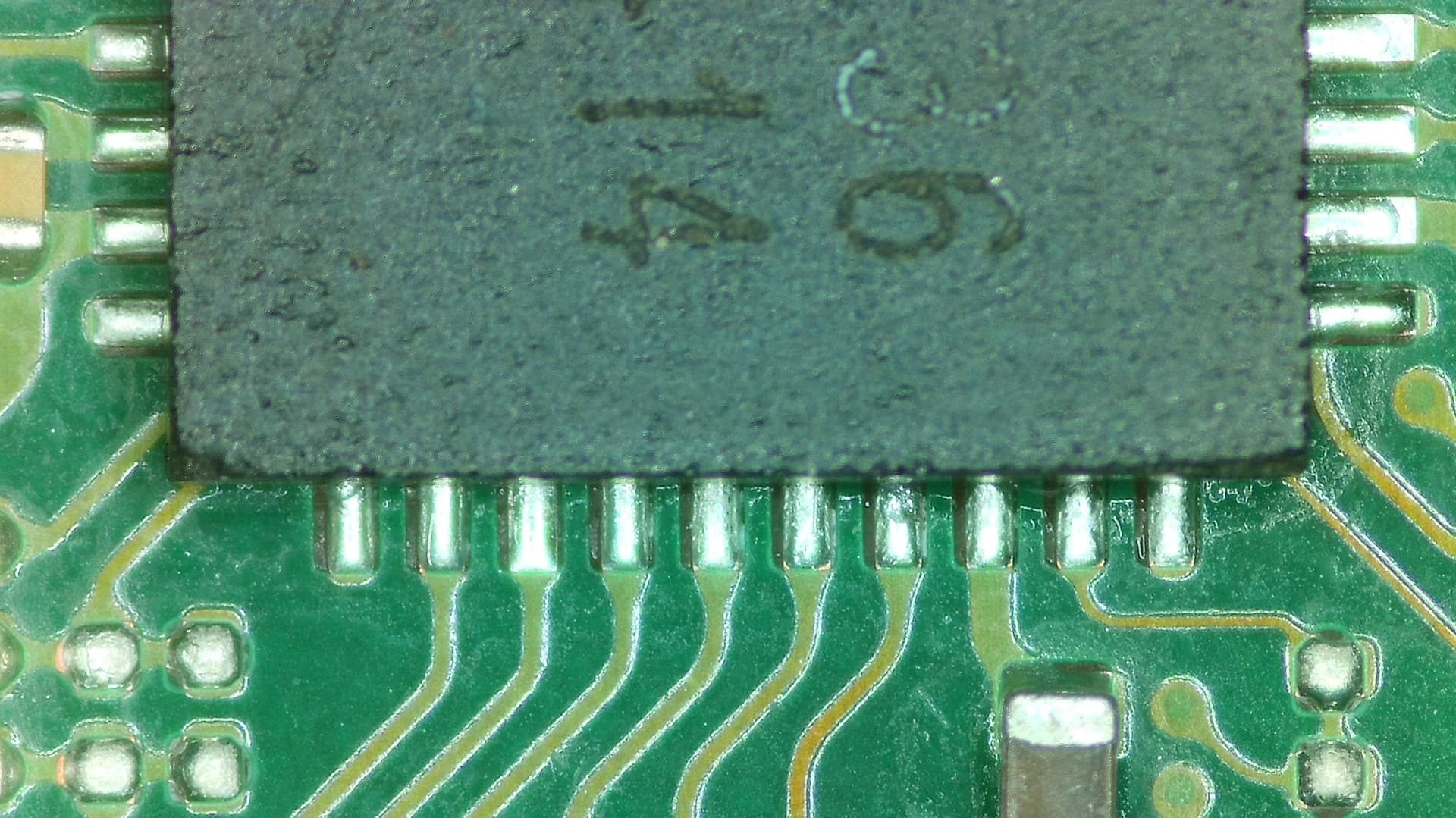
It’s pretty obvious from the the photos that the OP has not properly soldered the M92 IC as evident by the joints.
Also, given that the issues seemingly occurred following M92/USB install it’s likely the issue is M92 (as it has connections to 1V8PDR) or USB install (or bridge/damage as a result) or as has been mentioned a fake M92 IC… so likely the best course of action for the OP is to retrace his steps, remove M92 IC and see if the short on 1V8PDR clears. Following, provided no shorts, check battery voltage is at least 3.7V and see if the console boots with error code (because of no M92)
If shorts remain, LCD conn bent pins high likelihood. (which may be worth checking before doing anything as it also has connections to 1V8PDR too)
Recovery of values without M92
The LCD connector pins are ok, I checked the entire motherboard on both sides under a microscope and nothing abnormal.
Do you have a trusted site in Europe to buy another M92 chip?
I tested the 15v between the usb connector and M92 after soldering M92 and it was good.
To measure the 5v-15v current with my FNB58 tester I use the original Nintendo charger and an original usb-c cable from an oppo 9 lite.
3v3 – 14.44 K ohm then nothing 16.2 K ohm in reverse polarity
1v8 – 10.09K ohm
sys – 15.13 K ohm then nothing 10.89 K ohm in reverse polarity
1v35 – 5.17 M ohm but goes up to 9.55 M ohm then goes back down and stabilizes at 5.17 (1 M ohm for 20 seconds)
1v15 – 12.8 ohm
1v1 – 60.3 ohm then nothing 143.8 ohm in reverse polarity
CPU 0v8 – 39.6 ohm
GPU 0v8 – 12.5 ohm
5v joycon/fan – 3.28K ohm
Can you direct me (image, diagram, etc.) to show me how to check the 1v8PDR rail?
You’ve already meaured it afaict
While Sheriff’s image of measuring locations is convenient I am not familiar with all the locations myself and the measurments locations for some of these rails seem to be nonoptimal. For example, some of your measurments seem low (for the rails I think they are) but I can’t say for sure because of where your measuring… for example, is it because of trace length or because your measuring after a passive etc.
Instead, black probe on ground, red probe at the inductors surrounding the main Max PMIC. You can do the same at the inductors at the Max CPU/GPU regs too. (If your unsure, search the forum, I’ve talked about the primary rails on Switch to no end)
Anyway, it seems your short on 1V8PDR cleared after removing M92 IC, so either dodgy/fake IC or bad install. As for where to buy the M92 IC’s, I usually just buy high rated ones off eBay or Aliexpress, if theyre fake I just put in a dispute, if they try to force me to return for a refund (because they’re scammers) I just have my bank reverse the transaction, so, bit of a gamble… maybe someone else can suggest an easy place to get them without costing an arm and a leg ![]()
When I asked how to check the 1v8 rail I thought it should be tested in different places along its length. I take the measurements by pointing at the motherboard like in the image from PhynxVT posted at the beginning.
Is it normal that 3v3 - 1v1 and sys have an ohm value that remains a fraction of a second? and is it a short circuit when their values remain displayed when I reverse the polarity for the test?
I remember one thing, at the beginning when the switch started with an error code, when placing it on the charging base the green LED flashed continuously.
I do my measurement tests without the game card reader, without the SD card reader and without (the nand) connected to the motherboard, is it correct to do this?
this is part of the issue here, I know “3V3” is 3V3PDR but for “1V1”, while I could guess what this rail most likely is, I couldn’t say for sure without measuring my end as the locations your measuring these rails are not normal for me, add to it there is various rails that are around the 1V mark which can easily be confused (with no naming convention)
Anyway,
Remember your measuring in circuit so it’s to be expected you’ll get some eratic behaviour as a result, also, some meters are better / more stable than others in this regard. So yeah, don’t worry about it.
Sorry dunno what you mean, it’s a “short” when the resistance is virtually nothing, so, the 10 ohm you measured on 1V8PDR earlier was a short, if you’d have measured 0.8 ohms then that would be a dead short (as an example)
which makkes sense with a bad M92 / USB
Anyway, do as I said earlier, ensure battery has charge and see if the console boots once again with an error code, if yes then it was the M92/install that was the issue
If no, then perhaps your reading on 1V8PDR was 10K all along and you had your meter on the wrong range or something, in which case, your other rail measurements might be indicating a Ram issue (you’ve skewed it during M92 rework) but I can’t be sure until you measure at the locations I mentioned.
The console starts without the M2, of course provided that you leave the Emmc card on the motherboard, without it it won’t start, if ever it can help a beginner like me. I’m waiting for the new M92 chip now.
After a short break and purchase of equipment I continue my diagnosis.
I replaced my M92 chip (purchased a new one) but it doesn’t charge anything, the same as before.
3v3 – 19.72 K ohm plus nothing
1v8 – 10.85K ohm
sys – 16.62 K ohm then nothing
1v35 – 5.37 M ohm but goes up to 9.35 M ohm then goes back down
1v15 – 16.6 men
1v1 – 84.3 hom and nothing more
CPU 0v8 – 49.7 hom
GPU ov8 – 15.6 hom
5v joycom – 3.28K ohm
I bought a PCB controller to test the pins of the usb-c plug that I had also changed,
All contacts are good in continuity I post an image of the diagram that I created,
my motherboard is not the same as the reference image, if you see any errors?
Maybe it can help others.
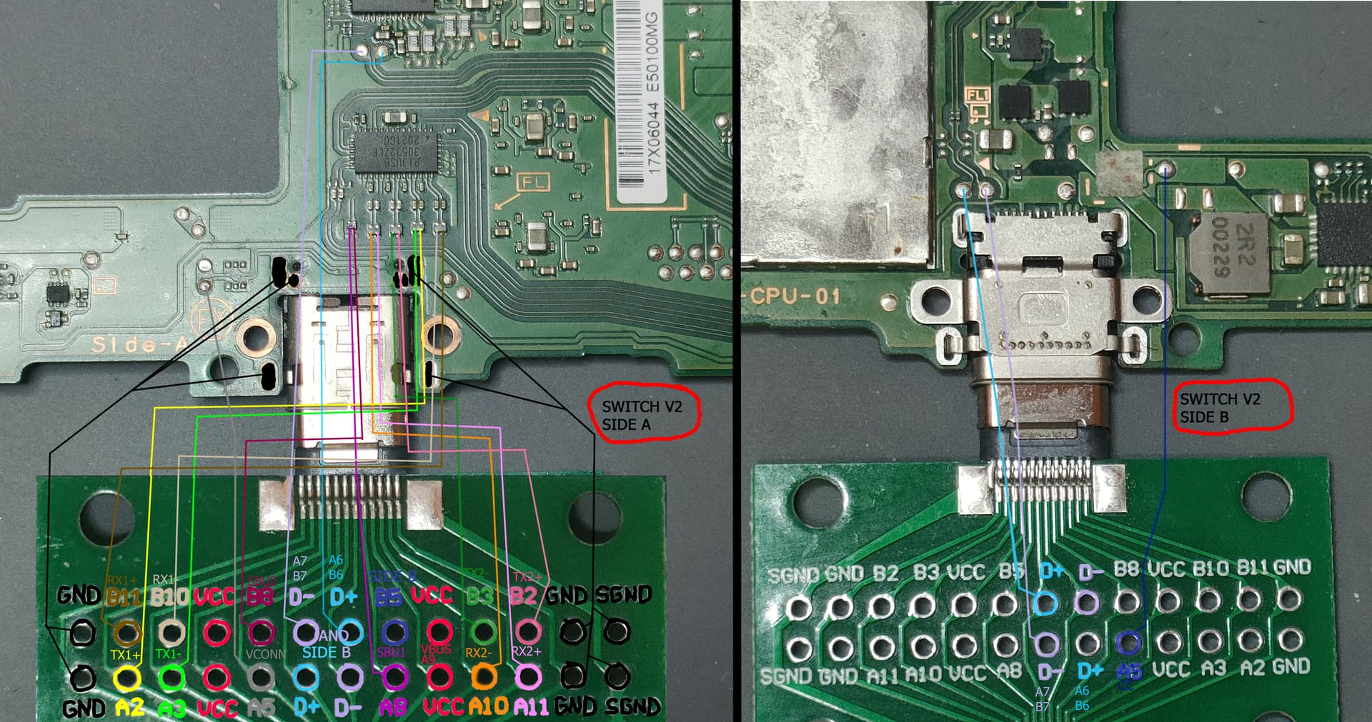
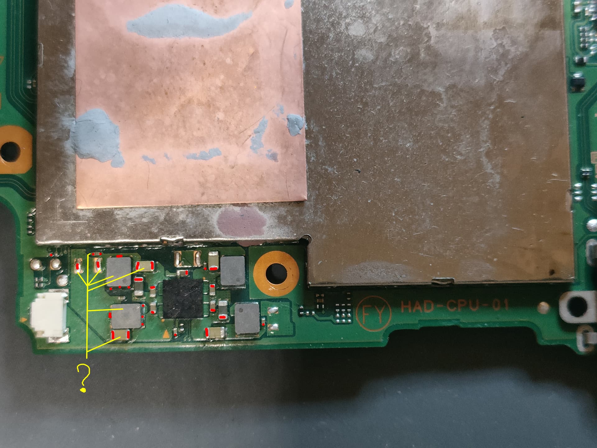
I also think I found a short circuit problem on side B, bottom left of the usb-c connector.
The red dots on the image are continuous, the yellow lines show the components which I think have a problem.
Do you think it’s the capacitors or the 2 gray squares that are h.s?
Thank you again for your help.