Does anyone have experience using this breaker board? Although it can be used or any eMMC in my case I’m trying to recover a Nintendo Switch one.
To test the process I bought a second hand Switch eMMC board of eBay which I know works as I can read it just fine with an mmclblkNX adapter. Nothing trough the Low Voltage board though and I doubled and triple checked the wiring. With the recommended Trancend SD card adapter the blue light goes off 10 times every 4 seconds and that’s it.
I’m using Windows, but I’ve seen others read their eMMC’s with HackDiskMount which is a Windows program, so that shouldn’t be the issue. Unless, there is a special driver I should be using however I haven’t seen any mentioning of that.
I’m not sure if this is a legit troubleshooting approach, but I also soldered a working SD card to to it and still nothing.
The adapters are fairly cheap and I could just buy another one, but it takes forever to arrive so I’d rather not just keep buying stuff if there is something that can be done about the one I have.
Few potential gotchas which can affect use which I’ll cover
When using the low voltage EMMC adapter you want to keep you lines as short as humanly possible all at near the same length and without crossing them if you can help it, consider on an actual SD card or dedicated board (like the Switch EMMC module for example) pretty much every other line inbetween a signal line is a ground, as well as sometimes having a ground plane above and below which serves as shielding, when your using point to point wiring your losing this.
Those Transcend SD readers are great but they offer virtually nothing in the way of shielding or signal cleanup/buffering. Unfortunately this is not a feature which the SD card readers advertise so it’s completely hit or miss whether another SD card reader has it… I had a cheapo pink SD card reader from China which utilised a COB micro, there was nothing special about the trace layout on the board (if anything it was badly laid out with bad length matchting etc) but it was obviously buffering the SD line signals as even with long point to point wiring from the EMMC/module if would still detect and read/write fine (where as the Transcend might fail to even establish a connection in this case) unfortunately this SD reader died (don’t think it liked being connected to a bad EMMC IC at some point) and as it was so generic I can’t find it anymore, best I can tell you it was chunky and in a pink semi transparent shell… I think I have the shell somewhere, if I can find it I’ll take a photo and you may be able to find one on eBay/Aliexpress
Last point, if the connection is established your likely only going to see the drive in windows disk management, chances are also high if your OS/system is anything like mine it will appear as “offline” because of a conflict with an SSD (or so it says) that being said tools such as NXNandManager etc have no issues accessing it.
It’s also worth mentioning you can’t access the boot0 or boot1 partitions via the low voltage EMMC adapter either
My leads were indeed a tad long, about 30cm each. I managed to cut them down to as short as 1.5-4cm. Still no luck. How crucial is the length matching? My money is on the RDF5. There is a neat thread on the ondroid forum that lists readers that are compatible with the ondroid eMMC boards. In there there are at least to mentions of issues with that reader, although the rest are predominantly positive (forum odroid com/viewtopic.php?f=53&t=2725). Anyone has experience with any of those? I wonder if the ondroid eMMC reader boards have the same 1-bit limitation as the exploitee. What’s more, I have a very old USB 2.0 SD card reader which actually mounts the card enough that HackDiskMount can recognize the size of the card (still cant read the contents though).
pretty crucial, if one wire were twice as long as another it could represent twice the potential noise pickup, skew, timing issues could be multiplied etc
I have about 15 different SD readers, all different and generic brands with the Transcend one being the only name brand in the mix, all of them work with EMMC IC’s without issue (provided the point to point wiring is short and matched) and I’m yet to find one which doesn’t and same goes for them all working in single bit mode, that pink one was the only one out of that entire lot which would tolerate longer/mismatched lines, so they’re quite rare
Some of them do behave differently though, the transcend will give up trying to establish a connection after a few attempts (indicated by the LED) and will not continue until it’s power cycled, while some of the cheap ones I have will just continually try and establish a connection indefinitely (which might be helpful in some cases)
I hadn’t heard of or seen that black EMMC reader board on odroid before now, looks good, if your able to directly connect the Switch EMMC module up to it also then better yet, no point to point wiring needed then
according to the post
Native eMMC 8bit wide data interface, instead of slow SD 4bit width
So full speed
I haven’t looked into it but it’s possible the exploiters version is capable of higher speeds but they just haven’t broken out the other data lines (I’ll need to check this), though that being said, your wiring woes would definately worsen in this case if using point to point wiring, though tbh if I’m using it to recover data then speed isn’t my priority
I made the lines all 4cm exactly, but the reader would still not latch on to it. I’ll probably order couple of other readers from the ondroid list and try that; plus, the exploitee boards are sold out right now, so new one is not an option.
is this via the low voltage EMMC adapter?
Correct. I’m using a microSD to SD adapter as a breakout board to connect the microSD card to the exploitee board. Unlike the Transcend reader the no-name one actually latches on (indicated by the constantly lit exploitee status light), but the best I got is a drive letter and HackDiskMount doesn’t even see it (with the SD card at least it reads the card size).
So far the ondroid list looks like a dead end, the Insignia reader (NS-CR2021) that was conforming working does not support 1-bit mode, so while it mounts a drive letter and reads the chip capacity correct of course it does not read the data. I’ve ordered another one (Ugreen) for good measure, but don’t have much hope about it.
I asked Ignas and he believes the mmcblkNX does support 1-bit mode, so I might try that next (once I figure out how to load the mmcblkNX schematic in KiCad:). One problem might be that the mmcblkNX board runs both Vcc and VccQ at 3.3V which is fine for the functional eMMC I use for testing, but it might not with the potentially unstable one I’m trying to save.
Try just ordering some generic one off eBay/Amazon and see if you have any luck with it vs your transcend etc
Yeah if I remember right it supports single bit mode fine
Right, it’s a shame… this would be a pretty good device if not for the devs misunderstanding of the EMMC spec… maybe he’ll revise it at some point.
I suppose you could just bodge in some 1.8V LDO and cut the existing VCCQ traces going to the connector… though I don’t recall if you have to engage the rails in a certain order, so it’s worth checking that prior
So I managed to open the board schematics in KiCad and the strange thing is that the RTS5170 controller does supply 1.8V and there is even test pad connected to it. I looks like Ignas went out of his way to make both 3.3V, so he must have had a some reason. Actually, it shouldn’t be hard to connect pads 15 and 16 to 1.8V; just cut a trace and bridge the two test points.
I’d just caution - I would double check this indeed a dedicated 1.8V supply rail and not some other misc 1.8V signal… I only say this as from memory this IC doesn’t have a datasheet, so it’s entirely possible if this is labeled as 1.8V in the schematics but could well be wrong and/or it’s only capable of 20mA (for example) which may be inadequate
While I do read 1.8V on that rail you have a point, if this is a strictly a SD card reader chip there is no need for 1.8V on it and since the data sheet for it is impossible to find it’s kind of crap shot what it is for. I guess I could use the exploitee as kind of a power supply; it wont be pretty, but beats frying the RTS chip I suppose.
One very important point which I completely forgot about,
What is the logic level of RTS5170 I/O (dat lines etc) ? I’m guessing they’ll be 3.3V, and I’m pretty sure they should be 1.8V
So providing the VCCQ rail either by bodging in an LDO or providing it externally probably won’t solve this issue… you’d also have to have a level shifter prior to the lines in question prior to the connector or just after the connector together with providing 1.8V for VCCQ
Bit of a shame as I imagnie the chip is capable of operating at a 1.8V logic level natively (indicated by that 1.8V showing up at that testpad) but without the datasheet it’s impossible to know how to set this
Yeah, there is that “small” detail, true enough. Anyway, I tried the mmcblkNX in 1-bit mode using a SD card this time and no luck with that too. My leads are a bit on the long end as the soldering points are very fragile, so it’s not definitive by any means, but so far I just cant catch a break with this.
A second SD card reader (Ugreen) identified in the ondroid forum list is not supporting 1-bit mode. At this point its pretty definitive that the 1-bit mode support is not a perquisite for ondroid eMMC board compatibility, so that list is not a good source for finding those.
Besides the length, how important is the wire material/gage/insulation? I’m using fairly thin enamel wire from a power transformer bobbin.
I don’t think any of the current options are all that great as an all in one solution…
I’m currently trying to find a modern day SD/EMMC USB controller which has all the functionality we would want and more importantly one which has the datasheet availiable. My main feature requirement is the ability to access the hidden boot partitions which would in turn need the dedicated driver for windows/linux… unfortunately this is a tricky thing to find as it doesn’t look like they advertise this as a feature even in the datasheets of IC’s which I expect actually have this functionality, for example, I’m going to take a guess that the Realtek RTS5169 has this capability and another guess that the driver is the same or near identical to the RTS5170 but there doesn’t seem to be any mention of it.
Better yet an IC with dedicated Nand I/O for more advanced recovery situations amongst other things would also be handy.
I’ll keep my eyes peeled and if I find an IC which looks like it will fit the bill I’ll design a PCB and spin something out. If anyone else manages to find an IC which looks like a fit then I’d appreciate it if you could let me know, or if anyone want to look into this then you’d probably stand a better chance at finding a controller by looking at Linux documentation as opposed to the IC datasheets
For material, copper is fine, any type of insulation is also fine. shielded cable would probably be optimum for point to point wiring
Should be fine, as for wire gauge, this is a ticky question to answer which could well change with line length among other things, I’m sure there is some complicated calculation an EE could perform to best select the most appropriate but in my case it would be easier to view the signals on a scope and adjust based on what I see is most optimum on screen, which unfortunately I haven’t done for SD/EMMC signals
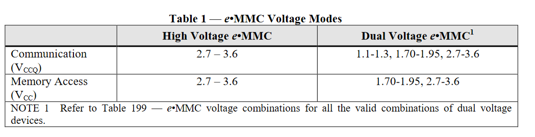
Emphasis on the “Dual voltage eMMC” section, the ranges there doesn’t mean an EMMC has to tolerate all of the upper ranges but rather fall within the bands, not all EMMC ICs are the “High voltage” variants, and as we have discussed, data recovery on an bad or failing IC stands a better chance when we use a lower voltage on the EMMC primary rails…
No clue about this… seems to me a few pennies for a level shifter would solve this problem…
Just to add to this, as I feel this could go back and forth a few times, and the dev may claim I’m wrong or I’m misinterpreting the EMMC specifications or something
If you skip to page 12 where it explicitly states the power supply voltages of VCCQ maximum is 1.95V
This is just one of many examples of EMMCs not supporting 3.3V on VCCQ, and while there are a lot on the market that do explicitly support VCCQ at 3.3V (and some which don’t but will tolerate it) it’s not always a given…
Just a few other points to note which limit mmcblkNX device functionality, say your working on a Switch Lite, the EMMC is soldered to the board, you point to point wire up to the relevant points but you would potentially kill the EMMC (if it does not tolerate VCCQ at 3.3V) and you would likely risk damaging the rest of the board as your basically applying 3.3V to what is normally a 1.8V rail… I appreciate this isn’t the intended function of his device, but had VCCQ been operating at 1.8V then this would be possible, and useful.
EMMC ICs aren’t particularly very tolerant to hotplugging at the best of times, but I’ve found there far more eager to die when VCCQ is at 3.3V… you might be thinking “I won’t htplug it” but in the real world, when some junk get’s stuck in the connector or your USB connector on your PC is a bit sloppy, your inevitably going to hotplug it at some point in time