When soldering the ribbon of sx core, the capacitor SP1 was pulled off from the PCB and the upper solder pad is missing. I tried to fix it by finding the trace that is originally connected to the pad. However, the copper around the pad is ground. If the pad is connected to the other layer of the PCB, there must be via but I didn’t see any via around the pad.
Does anybody know where the SP1 capacitor connected to? Is SP1 in parallel to the SP2?
It’s the 1V rail i think, it’s supplied by max pmic on back of the board and yeah think it’s in parallel with the other cap but i’ll have to check…but wait!!! don’t apply any power and disconnect the battery then take a better pic of the soc zoomed out higher res so i can see the extent of the damage… and whatever you do don’t take your iron to that mess you’ll make it worse, you will not be able to remove the solder after… it may already be dead
The switch can boot and run games normally. Are you sure it is 1v rail to rail? The large exposed copper is the first layer(ground). I think the marked area is the second layer of the pcb, which was connected to the missed solder pad. We can see a clearly boarder. I also test the connectivity between the markered area and the ground, they are not connected
I plan to fix the exposed area by pouring the green oil. Then, I fly a wire from the marked area.
Yes but before you do that i want you to disconnected battery and measure resistance to ground on the other intact cap… it’s supposed to be low but if you’ve mashed layers together and the reading is lower than it ought to be then the soc will not last long…hence : turn it off and unplug battery.
two readings please, one with black on ground and red on caps positive and second with red on ground and black on caps positive… note:i’m after resistance readings not diode
It’s advised you don’t touch the area with damage it won’t take much to deform the exposed layers with a probe, for example
Will mention this for others, don’t dig out pads on the SOC, it’s multilayered pcb with a silicon die, i’m shocked the op’s switch still boots… this shouldn’t be done at the best of times on a regular PCB atleast without first verifying on a scrap donor to see whats below, how many layers etc
I always keep the battery unplugged during measurement.
“two readings please, one with black on ground and red on caps positive and second with red on ground and black on caps positive… note:i’m after resistance readings not diode”
Do you mean the using the resistance measurement channel of the multimeter?
I didn’t notice the position of red and black. I used the connectivity / diode checking channel to test the conductivity.
diode mode is useless on such a low impedence circuit… make sure to take measurements on the intact cap and not the damaged pads
continuity mode typically doesn’t register unless resistance is below 30ohms, but this varies between mulimeter brands/models, which is why i want actual resistance readings in both directions
Yep. I can understand. That’s why many points were “conducted” when measured with the diode channel. The switch is not beside me currently. Maybe tomorrow I can confirm the resistance.
What should be the value? Why alternating the red and black probe? To check if the two values are the same and if there is a parallel diode?
This again depends on the make/model of the meter which is why i generally insist on actual resistance readings and not diode - not least because values vary wildly from person to person… diode readings generally should be used as a personal pass fail compared to your own working donor, anything in between then check resistance.
I’ll check the values for you later.
to check transistor/diode junction is functioning, typically one way round will be higher and the other will be lower.
Ok , thank you. Why can’t I insert a figure in the post? If I can measure the resistance and label them on a figure to show it. Let assume that the resistance is confirmed to be normal. What should I do next?
And do you know which capacitor I am talking about?
don’t know what you mean by figure, sorry… symbol? image? document?
If i confirm the readings are good, then you’d want to delicately clean the damaged area/pads with ipa… and i mean clean, Spotless! you don’t want any copper particals hanging around in there. then heat at 100c with hot air for a few seconds to fully dry the area, then cover in green conformal coating, heat to 100c for 30seconds and hit with UV light for 10 mins
forget about these pads, theyr’e writeoffs now, any further attempts to revive them will result in a switch sized paperweight… i’ll find another location for you and show you in an image what to do
Clean the area gently and and re-measure on the good cap, if all is well then mask it with conformal based on my previous instructions.
Test the SX flex and ensure corresponding pads are in parallel, if they are then no jumper is required and you can get away with just soldering to one cap.
It is advised to not solder the two ground pads to the shield frame…I’ve repaired several with damage in this area, plus the solder prevents the heatsink top/plate from sitting flush.
Ensure the IC on SX flex is slipped under the metal shield surround.
It’s also advised to practice on a dead laptop/pc boards CPU (wire to cap) prior to carrying out this job so you can feel confident in the outcome :without worry
It can’t boot now… With the sx core soldered, the sx core will light the pink led but the screen will not light. Without the sx core soldered, the screen also keep dark. The voltage of the battery is 4 V. What might be the problem?
Retake the resistance measurement on the intact capacitor the same as before and ensure the readings are the same as before.
I don’t recall the error colour codes of SX core, but i have a feeling pink indicates a short typically, either that or failure to detect EMMC… i forget.
Check that you have not bridged the capacitor/s etc can you take a clear photo that’s more zoomed out than last time?
There is no significant difference on the resistance. The switch is not beside me now. I had left the switch in office and plug the charger on. Maybe it needs some charging>?
I think you need to retake the measurments when your next in the office to be on the sure side that there is no issue.
Aterwards, if the resistance measurments are good, then plug the battery back in, promt it to boot with the cable and measure the voltage on the intact capacitor, it should be approx 1V (be very careful here, you are in close proximity to several other rails on the other caps). you should be able to use a USB ammeter here too so you can monitor the current draw as well, if the current draw is excessive then it indicates a short circuit while the device is under load… sometimes bad capacitors will behave like this (short only under load)
 The switch is not beside me currently. Maybe tomorrow I can confirm the resistance.
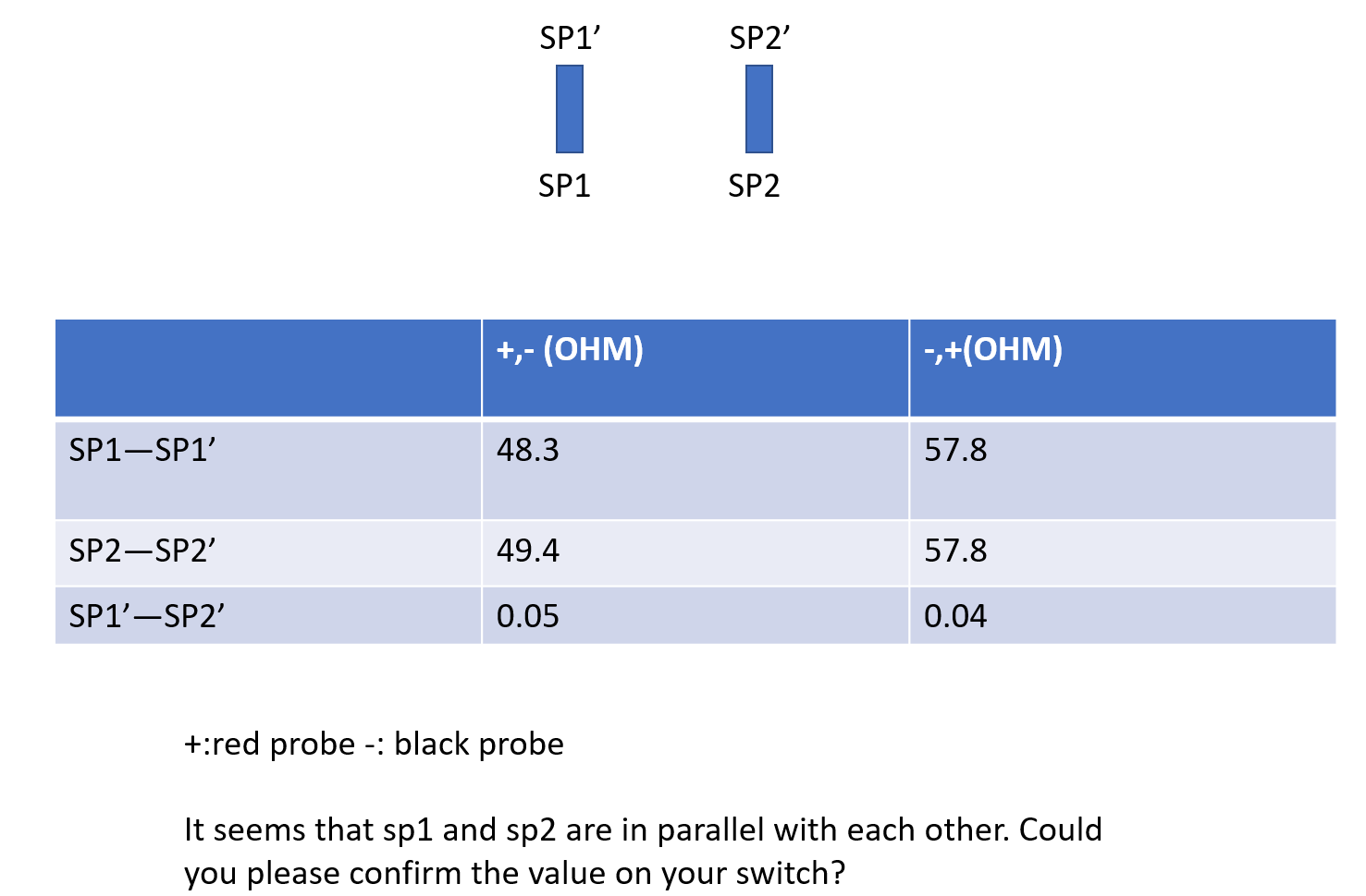
