The capacitor is brand new. I am worry about if the switch has already dead. 
1 Like
-based on the information i am seeing online and my experience (from memory) purple/pink light does indeed indicate a short… typically as a result of poor soldering on the capacitors…
The reason i told you to practice on a scrap CPU is for this reason, no offense but the original damage was caused because of a poor install to begin with 
Don’t panic and when your back in the office tommorow stay calm unplug the battery and peform the above tests i mentioned, also check the BQ and M9 chip for shorts also.
Thoroughly inspect the capacitors on the board for any potential debree/solder etc
And please take photos of you replaced capacitor install
not easily no, not unless your supplying the 1V rail from a bench PSU and the meter is running in line with the PSU output… which i don’t advise you try.
Don’t under any circumstances put you meter in current mode and directly probe the board, this is not how measuring current on a meter works, if you were to do this you are in effect creating a short circuit accross your probes
Just to confirm, did you install the capacitor with hot air or a soldering iron? -
solder iron。It’s hard to use hot air because the ground absorb large amount of heat.
Good. Yeah, don’t use hot air here it’s asking for trouble
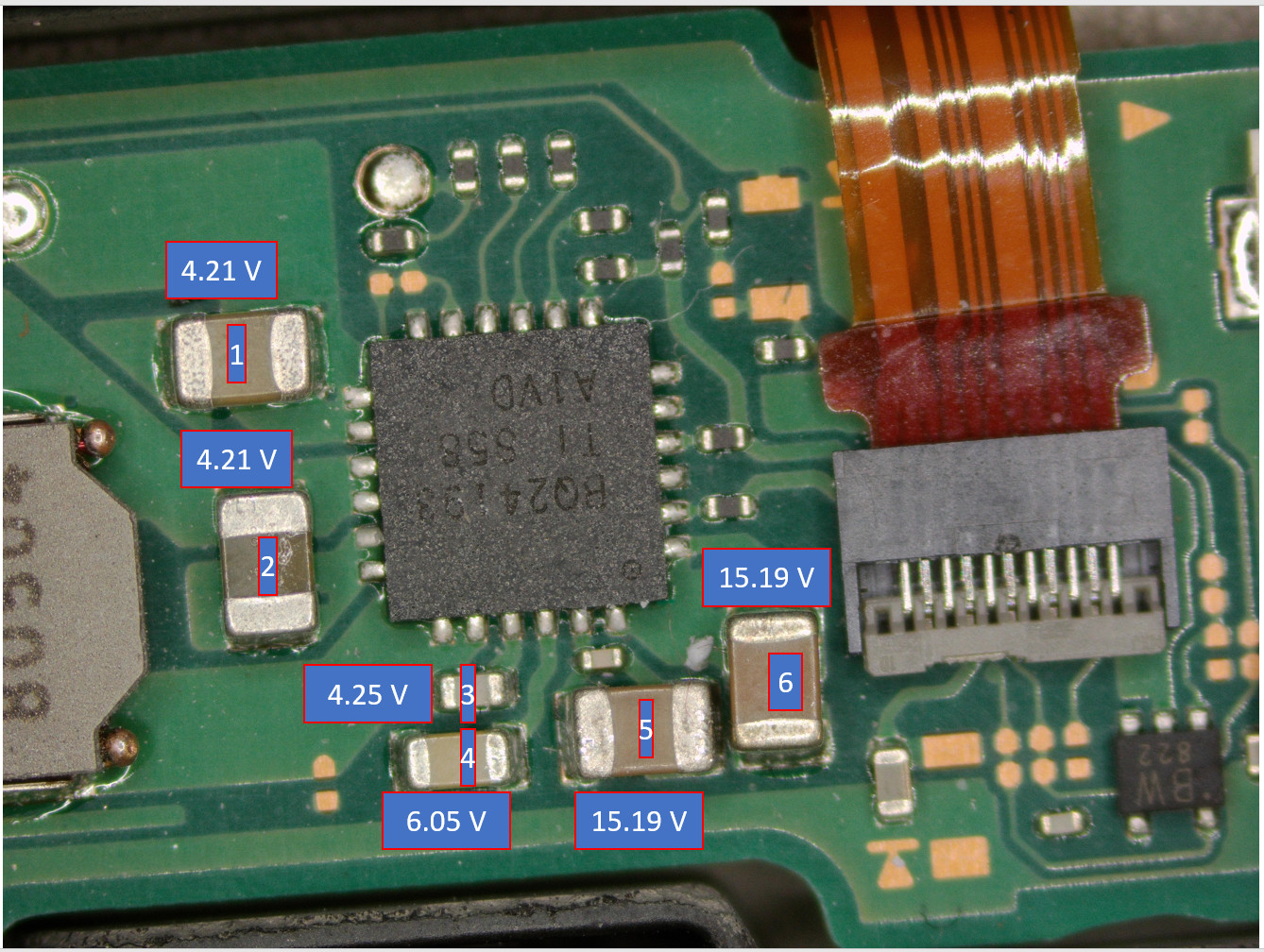
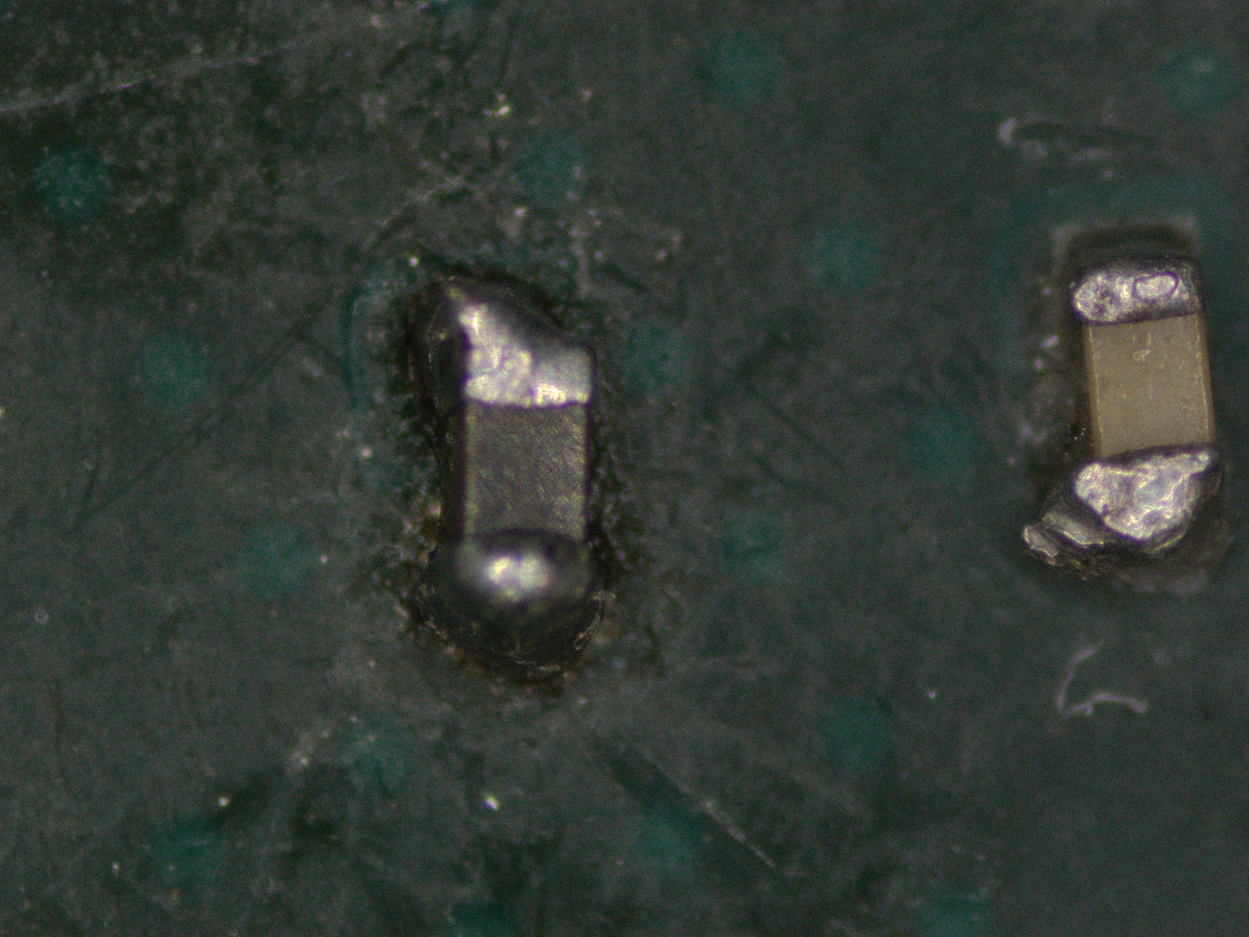
Those caps look a little sad.
What is the resistance measurments on them? do it the same way as before.
You could also try putting a few drops of IPA on that area with the battery plugged in, and power cable. If you see the alcohol boil off when touching a particular cap it would point to a cap that is bad when system is under load.
SP2. 53OHM, 62OHM. There is no significant difference.
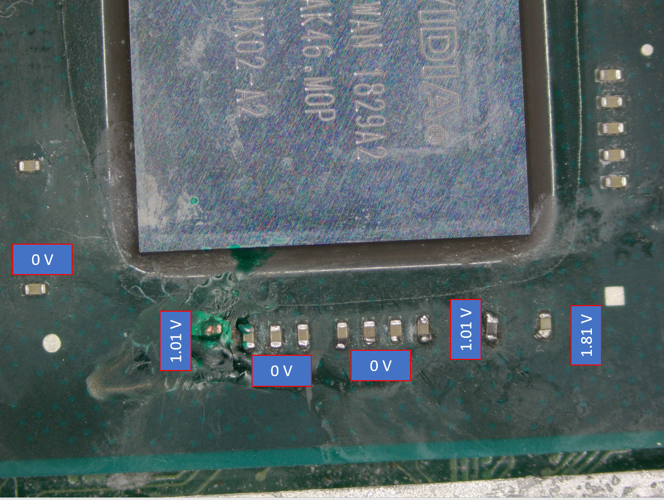
If that doesn’t reveal anything then you can also unplug and also measure the resistance on the caps showing as 0v in your picture, from memory i believe theyr’e provided by the max ic just below the soc, if this rail is being pulled low if could produce your symptoms
No boiling. bottom(0V) 80ohm ,66ohm. Left corner(0V) 0.05ohm.
those values are acceptable.
after you applied the conformal coating but before you installed the replacment capacitor and before you installed the SX-core, did the connsole still boot at this point?
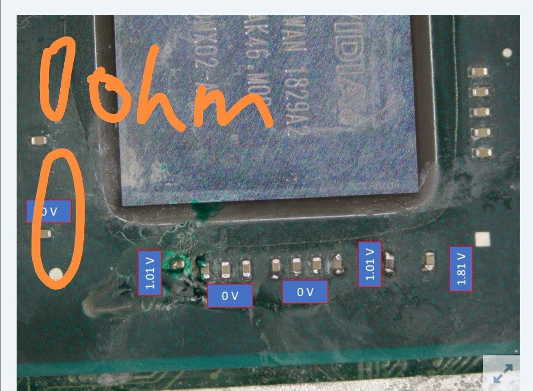
This cap is ohm to ground. Is it normal?
The switch can boot into ofw after SP1 is lost and with SP2 replaced before I post this question.
I tried to reinstalled the sx core as you said yesterday. Before installation, I didn’t try booting the switch. After the installation of sx core, I still get pink led and the switch didn’t light. After removing the sx core, the switch still can’t be booted.
Yeah it’s normal.
Hmm this makes this harder for me to diagnose virtually.
There was a short present when you installed SX core the second time as indicated by the pink/purple LED which means it’s entirely possible it could have done something to your EMMC.
I would also inspect the connector on your EMMC module, if there is damage to the connector then the console won’t boot.
Last thing i can think of, test your SX ribbon is still good and make sure the positive side of the caps pads on it are not shorted when it’s connected to the SX-mainboard, then
reinstall SX core without EMMC module connected to it (practice first on a scrap CPU etc) you should get a red light from memory
If that’s the case then disconnect battery/power again and install the EMMC module in SX core, making sure it’s the correct way round, don’t hook up an SD card, hopefully you get the SD message on the screen. then we’ll go from there.
Maybe this goes without saying but also check your LCD connector is good and has no bent pins inside.
This would be easier if you had a USB ammeter as it would tell us if fast charging is working which would indicate second stage boot process is good.
I had ordered a USB power meter. I think the lcd connector is fine because I never touch it.
can you provide resistance measurements on the last 1.8V cap too?
It’s two pads. To ground. 0hm and infinity respectively.
should be approx 10k on this particular rail.
Reverse probe/change polarity and take the measurment again
The resistance is not fixed and it will keep rising to 30k and 29.5k. The channel is 200kohm range.
this doesn’t sound right, light me check on one of my donors