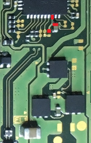
With black on ground and red on the positive side of this cap, you should get approx 10k
With red on ground and black on the positive side of this cap, you sould get approx 13k
If you trigger the transistor/diode junction (for example you slipped with your lead and touched something else) then the positive side of the cap can in some cases can read OL or high meg
btw checked on 3 donors and 2 working boards.
based on your readings something seems to have become open circuit on this 1.8V rail
At what point did you attempt using hot air on the capacitors?
Should also mention my measurments are all based on the board only with no LCD or other ribbons connected, i don’t know how they will alter some of the readings if they are connected.
Hopefully this goes without saying too, but don’t connect the joycons either through any of this process
I had tried the alcohol and there is no evaporation.
The different resistance might be the influence of compnents connected. Plus the tin under the hot air area didn’t melt, how could the other area be heated?
While the resistance isn’t a dead short on the 1.8V rail it should atleast be drawing 77 Milliamp which should make the culprit at least mildly warm and presumably the resistance will drop under load/heat increasing the current draw.
doesn’t matter if the balls below didn’t fully melt, you might have got them just above the transistion melting point, or warped the board…
I have my doubts they’re altering it to this extent, you could prove this point by disconnecting evrything though and retaking the measurments.
Also now you’ve changed your meter to an auto ranging, you might want to re-take all the measurments on the other caps also just so i verify your result consistency
Yeah i know, but can you check them again with your yellow meter, i want to verify the integrity of your readings/results. When you measured the resitance of the 1.8V rail to ground you were getting very different results between these two meters which is concerning.
At this point no, if your 1.8V rail is 23ohm relative to ground i can’t imagine the console booting in any form or fashion, this issue needs to be resolved first
Oh ok, in which case it’s too high one way and too low the other.
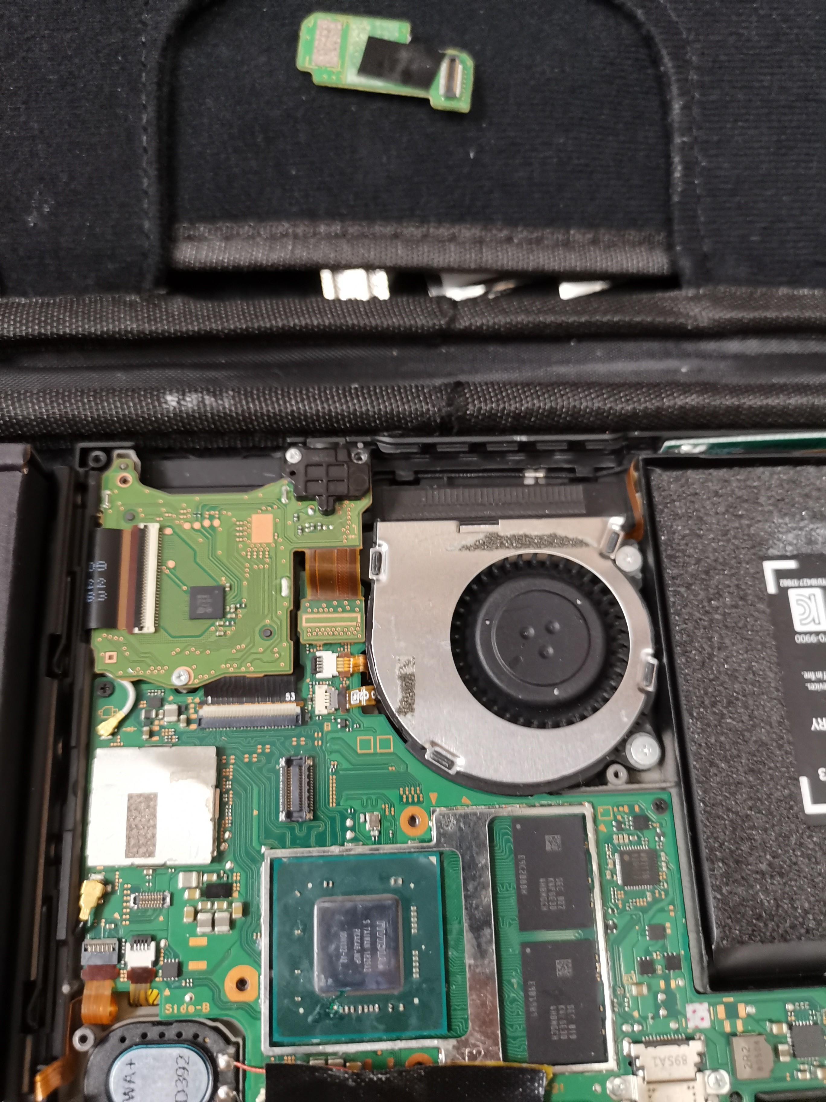
Think you should disconnect all ribbons from the assembly and GC PCB and retake the measurments here… even so can’t think why it would have an impact, particulary relating to your 23.36kohm reading. But it doesn’t hurt to verify.
could also try putting slight downward pressure on the soc while taking this measurment and seeing if the resistance changes which would point back to a bad connection under SOC.
Or you could try applying mild heat on the SOC (100c for 30 sec) and retaking the measurment and seeing if the resistance significantly changes
Not at this point, just remove all ribbons and disconnect the GC connector
take you measurments at any of the following points relative to ground as it’s safer than constantly probing caps on the soc, the points marked are on the same rail.