Will do it tommorow. What will be the next step if it is normal?
If it measures approx 10k one way and approx 13k the other then proceed with earlier recommendations with SX core but keeping all ribbons disconnected until we can verify some signs of life
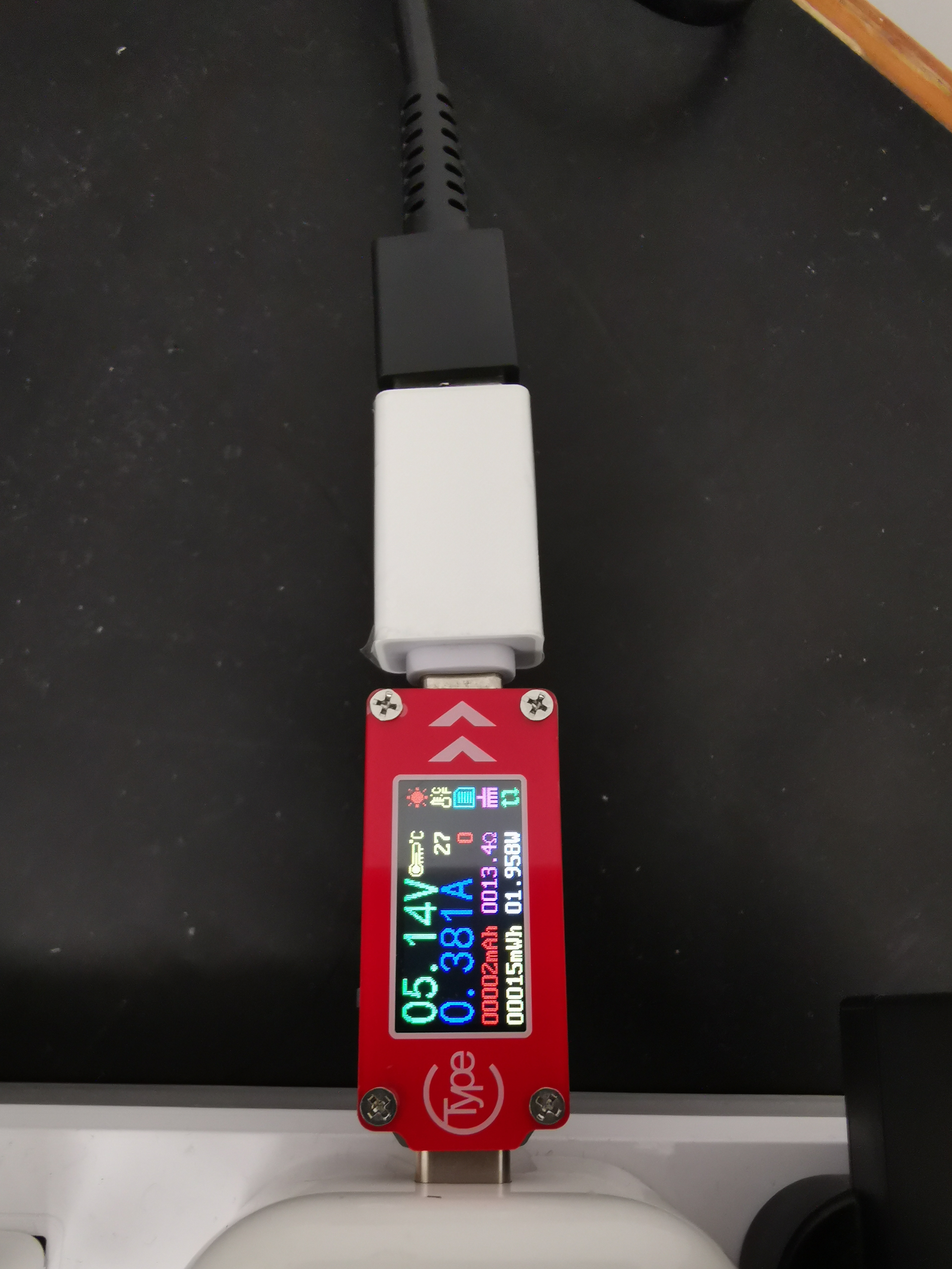
I test the switch using ammeter. The charger belongs to Iphone 12. Output 5 V.
With the charger connected, plug on the battery, switch is in off state: current is 0.288 A.
With the charger connected, plug on the battery, after pressing the on button: current is 0.327 A.
With the charger connected, disconnect the battery: current is 0.062 A.
Moved all the connectors, the resistance is still the same as the previous value.
Also tried to reinstall the sx core.
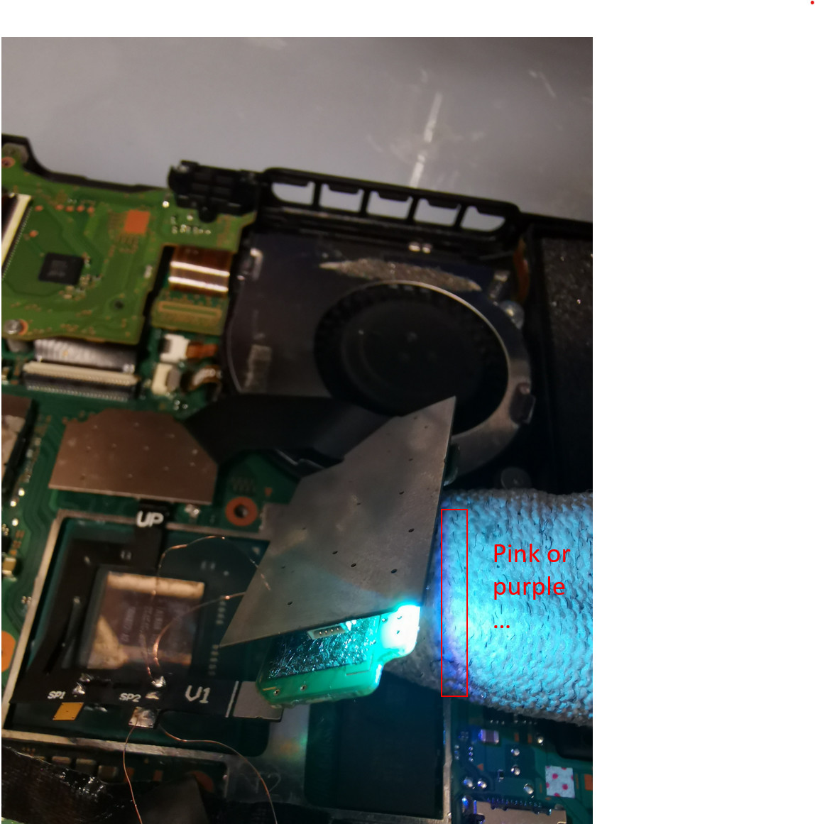
It always flash blue for a while and then turns to pink led with and without the EMMC module connected.
I use two enamel insulated wire to connect the ribbon to the SP2 and the connectivity is fine.
Can you test with another fixed 5V USB charger? i believe the apple ones can output 9V/15v+ but i am unsure if it would boost in this instance… but some of the cheaper USB ammeters will not display the correct voltage output even if boosted. I am more familiar with current draw at 5V and if it’s boosted it will skew these readings.
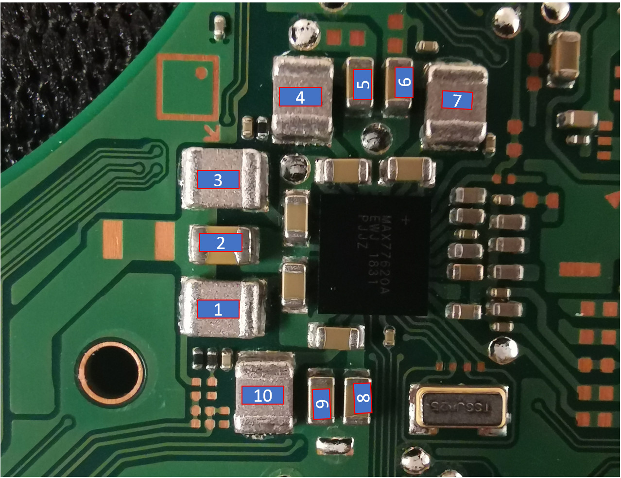
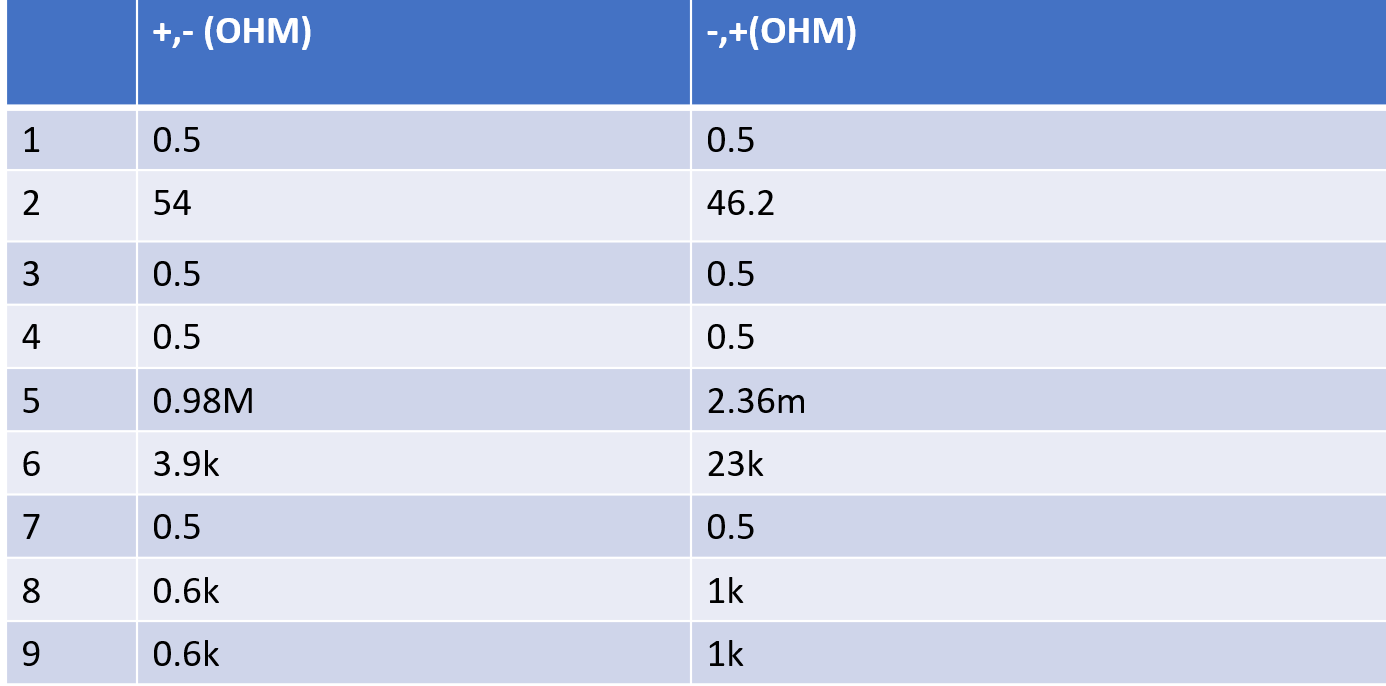
on first glance, apart from your 1V8 rail measurments then the other readings are acceptable, your measurments on 5 appear erroneous and should retake to make sure.
(for anyoe else, the readings on the inductors are being measured across them and the results are irrelevant)
Can you confirm the IC (6-pin i think) on the SX-Core ribbon flex is not touching the metal shield? even so i do not think the switch will boot with the 1v8 rail in it’s current state
I guess your enamel jumpers are going to the relevent rail on the back of the board? if so i don’t think it’s a good idea to run such a long wire, i’m not 100% sure what TX is doing throughout this “glitching” process as i have not read up on it or looked on my oscilloscope but it’s possible it’s a high frequency signal, if so, with such a long line it could have negative results.
It’s rare for the Max PMIC to fail, it’s even more rare that a bad PMIC here would still produce all the other rails so you can rule that out.
you might try my earlier suggestions
If nothing changes then unfortunately it is seemingly becoming more and more likey that one or more of the solder balls below SOC have joined/disconnected either/or, or that 1V8 has came into contact with the 1V rail ![]() I don’t know how tolerant the SOC is to overvoltage conditions (maybe someone else can answer if overclocking is a thing on switch?) … but this is a situation where it would be easier to confirm in person.
I don’t know how tolerant the SOC is to overvoltage conditions (maybe someone else can answer if overclocking is a thing on switch?) … but this is a situation where it would be easier to confirm in person.
At the beginning (when the switch is normal), when the sx core is installed, the switch will always boot into OFW with the pink LED lighting. So I think sx core will not change anything since it never communicates with the band successfully.
I think the ammeter is fine, when connected to the original charger of switch, it will show around 15V. It didn’t output 9V/15v is because the protocol of charging is not detected.
If the 1.8V rail is connected to 1 V rail, it can be detected by the multimeter easily, right?
Could you please check the.resistance between 1.8 v rail and 1v rail for reference.?
Then even at that point there was an issue and a potential short… disconnect SX-Core and update it’s fimrware via the debug USB to rule that out just in case.
btw SX is not communicating with the SOC via the flex on caps, this is just a voltage rail afaik, this is not a signal path, the “glitching” process takes place on this rail to put the cpu into a certain state (presumably a panic state) and afterwards the SX micro intercepts and modifies the bootloader on the EMMC module, the short/pink LED is indicating the SX is unable to do this for whatever reason
Your ammeter is fine, it’s showing approx 0.4A which is typical standby charge which indidcates your switch isn’t clearing the initial boot step.
possibly but in this case, as you’ve made modifcations and removed and installed SX-Core multiple times it’s possible the short has already been cleared and 1v8 no longer has reference to 1V.
I can, will be able to check in an hour or two
Tested the 1.8 v according to the picture in a post (I can’t insert a link).
The value is under the diode channel.
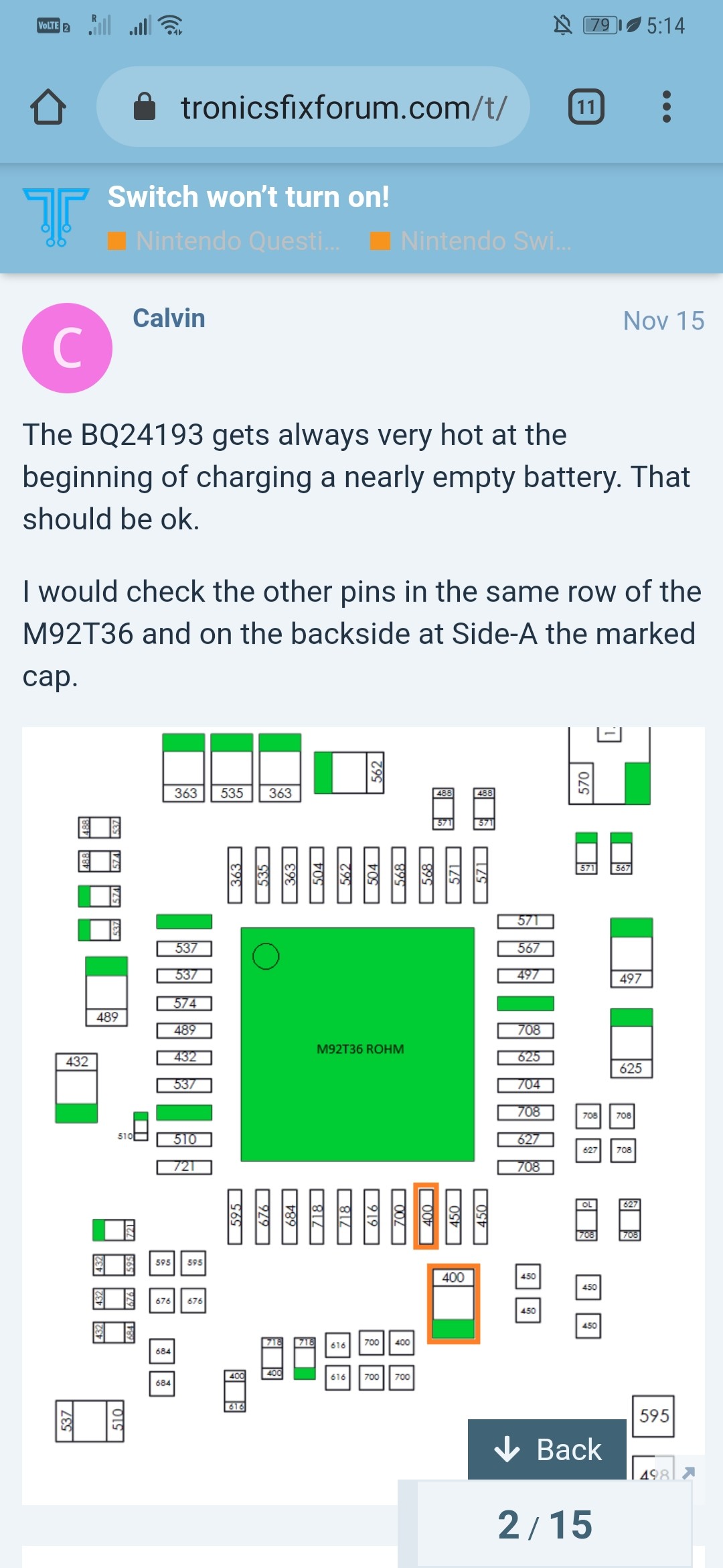
The result is the same as that in the picture.
I measured the 1.8v and 1v rail, they are not connected.
This might be a problem. If it had done some damage, there will be somewhere shorted.
If this is the problem, I think the best choic is to send it to a repair store.
I’ll get the measurements for you on the 1v8 and 1v rails but afaict OL/not connected would be normal in this case. In the meantime, try some of my earlier suggestions that you may have overlooked and post the results.
I agree, but would advise you make sure they are capable of reballing (the soc in this case, plenty of repair shops claim to be able to do these repairs but can’t and botch them even more than originally) and if you do, point them to this thread so they have a better understanding of the history, you’d be more than welcome to send it to me but i expect that by the time you pay for delivery two ways it will cost more than the switch is worth. Where are you located? maybe i can find an honest repair tech for you.
@FXDX is capable of reballing very well and he maybe closer to you and willing to undertake this repair and do a reball if that is the issue
I had tried to heat it for 30 sec and measure but no difference. Do you mean resoldering the SoC? I think we are not in the same country…
No, numerous voltage rails are present on soc balls, if you bridge one (or another as the case may be) then you’ll destroy the soc (if it isn’t already fried that is) or at best you’ll decrease repair likelihood by someone else
btw your welcome to send me a PM if you can figure out how to do it… i have no clue, can’t find the option
Will the ultraviolet light hurt the circuit? I had used it to fix the green oil for above 20-30 minutes. …
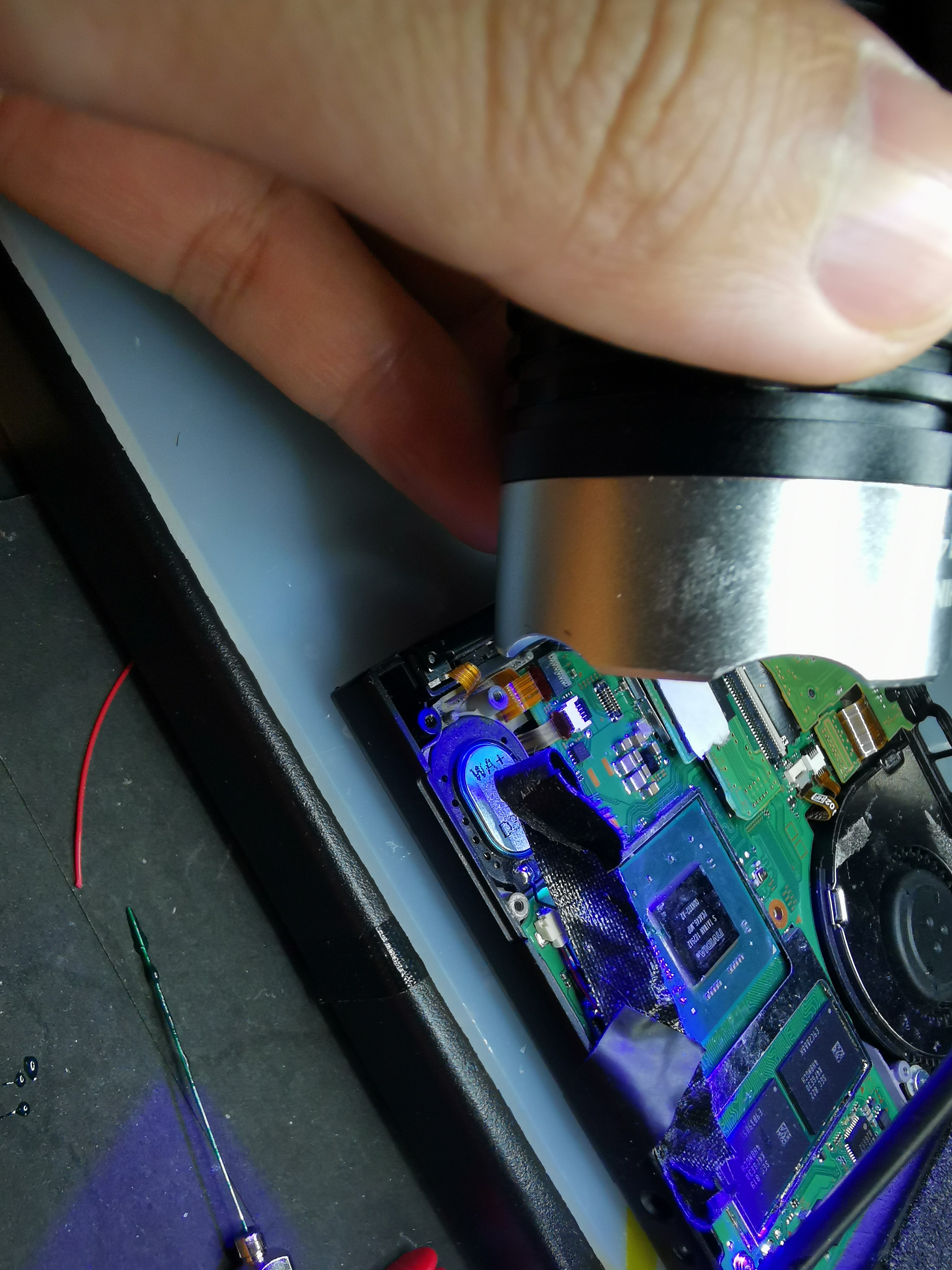
no, did a repair on somebody’s botched SX install yesterday which had bad caps and indent and scorch between solder pads and i used a much more powerful UV LED matrix compared to yours over the entire board for probably over an hour, doesn’t make a difference.
Is that why your covering max ic below soc because you were worried? or is there damage in that area?
No. I just see some post that some times the max ic below soc is the problem. So I just want to take a look but the result is fine.
Very strange.,I just solder the SP1 and SP2 during the whole process. If the 1.8v rail is bridged to the 1v rail. The 1 v rail
should become 1.8V. Except the resistance on 1.8V rail, we had exclude the problem of max ic,right?
I will go to a local repair store. I will feedback the problem once it is fixed.
Sorry, don’t think I’ve explained the symptoms and diagnosis of the suspected fault very well.
To begin with, the 1V rail in question is suspected to be CPU vcore, typically (but not always) CPU vcore is max rated at 1.2V on embedded devices, slight increases above this rating will cause stability issues but if the voltage goes over the “absolute max” ratings (which i don’t know, don’t have a datasheet) then you will kill the soc’s intergrated CPU. While i know for sure that the SOC can tolerate a direct short to ground on the 1V rail either because of or due to short circuit protection on the max PMIC (on the boards rear) or as a result of the heat buildup triggering an “alarm” on the temperature IC (next to the soc) forcing a shutdown…but… whether or not this soc can tolerate 1.8V on on the 1V rail is tbd… i have my doubts at least for any extended amount of time.
Now, to answer your question, just because/if 1.8V got onto the 1V rail doesn’t make it automatically create a short between the two rails (assuming that’s whats happened) after the inital short/bridge is removed. It could simply skew readings that should otherwise be good (for example the bad readings your getting when measuring the resistance to ground on 1.8v) due to internal damage.
Other indicators > the SX core shining pink/purple indicating a short on one or both of these rails, SX core receives and passes through 1.8V to the EMMc module and also outputs to the 1V rail (via the ribbon), this indicated the fault from the beginning and points to bridge between the 1.8V and 1V rail, though this is an educated guess, there isn’t a really easy way to tell without removing the SOC entirely. The other possibility is the balls below the SOC aren’t making contact because of hot air or several have joined together (or both)
A simplified analogy > Think about your desktop computer, if your overclocking it you are in turn increaseing the voltage to the CPU, there is typically safety measures put in place to prevent you from increasing the voltage above a point to prevent damage, though there are ways to bypass these protections in some cases, thereby increasing the voltage too much causing irreparable damage
I hope they are able to fix the problem, and hopefully the prognosis is better, i would definately make them aware of it’s condition up to this point so they can better diagnose and hopefully repair the problem otherwise theyr’e likely turn it away if they open it without knowing this info first (i would)