Alright got a weird one here for a nintendo switch, feel it’s on the cusp of life but just can’t figure it out at this point and hopefully someone can shed some light.
So switch is a faulty ebay purchase apparently it was taken to a repair shop who failed and the customer just sold on. However the p13 was shorted and around 12 caps/resistors/filters missing around the p13 as well as a tampered bq chip, a cracked fuel gauge and a couple other missing components.
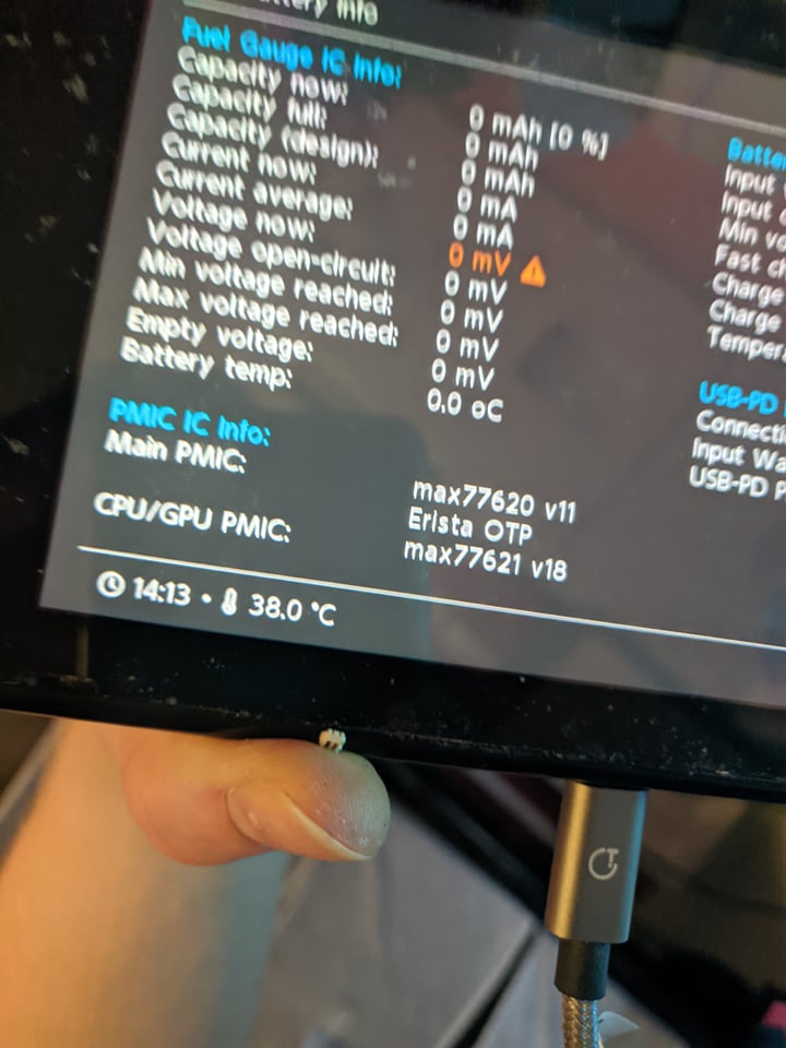
So after rectifying the p13 chip and replacing all the components we were met with a blackscreen upon boot at 0.4a charging so I suspected auto rcm or dodgy nand so I booted into hekate and rebuilt the nand from scratch as I obviously do not have a working backup. All is good despite the fuel gauge ic error in the screenshot and I go to do first boot and we get the nintendo logo followed by blackscreen and then a 0.4amp draw again.
Suspected the donor board fuel gauge I used was bad so tried another, same result, so bought a brand new one but sadly same result. So I decided to just replace the entire fuel gauge circuit (the surrounding components on the fuel gauge) as well as replace the BQ chip as it looked tampered with and just for the hell of it threw on a brand new m92 too. But lo and behold the error still remains. Have tested with different batterys and switch housings but same result.
As a hail mary I also removed the diode arrays as I know they can cause charging issues but aren’t needed.
At this point I’m at a complete loss. I do believe the fuel gauge is what’s preventing the boot up however I can’t be 100% sure but I do know the nand rebuild/downgrade has been carried out properly as I’ve done it many times but this switch is a real wrench in the works and haven’t come across this in about 30 switches.
Likely over rework of the USB, P13, BQ or fuel gauge areas of the board of which has caused layer seperation and open vias/lines… I’ve had numerous USB/P13 layer/via issues in recent times due to over rework of USB/P13, but it seems like fuel gauge/BQ lines being open is the new more developed fault now… then again, donors from eBay, not all that surprrised
A failure around the battery sense pin would give you a nintendo logo and then black screen. Might be worth checking a different battery or looking for corrosion on the battery connector.
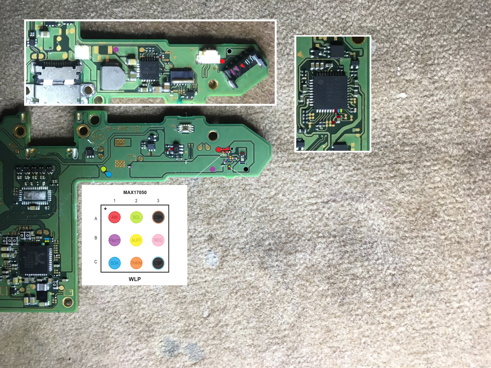
This is almost certainly a hardware issue. If the fuel gauge stats aren’t showing up in Hekate, and you’ve verfied the center pin on the battery connectors has continuity at the following locations, and your also getting continuity to the other points in my image
and if following a replacement of a new fuel gauge the stats are still not displaying in Hekate, then it’s likely there is an open line elsewhere (to/from the SoC for example) , which could be the result of board layer damage. You could also take diode.resistance readings on the the fuel gauge surrounding components in both probe polarities relative to ground and see if anything jumps out at you as being a miss comparing to a known good
Already done that prior to this post alongside replacing the entire fuel gauge circuit including the 3 different fuel gauge ics themselves as stated in the post but still no change. Everything around BQ is perfectly fine too.
Chances are it is damaged traces within the board as this was probably someones donor board chucked on ebay as a faulty device as p13 was missing along with about 12 caps/resistors/filters. Weird thing was a cracked fuel gauge but there was absolutely no damage to the pcb underneath so it’s a real strange one.
Can only assume something blew causing p13 to go alongside some deeper trace damage.
You also didn’t mention having a battery connected while checking for continuity? As I do not have continuity from the sense pin to various test points unless the battery is connected.
Edit: Actually just clocked that it links up to the two test points next to the realtek which the resistors feed into it looks like, along with the realtek chip itself. Somewhere I hadn’t realised was linked so I’ll check those locations too, be nice if it the line was broken there and a new realtek chip solved things.
Lines to/from BQ and Fuel gauge (and others) run past this area on inner layers, so if the person prior has cooked the board attempting to get the P13 off/on, then it’s potentially whats caused this issue
You don’t leave the battery / power connected when checking diode, resistance/continuity on any board and should always disconnect all power sources the only time you’d leave power connected is when checking voltage
If your not getting continuity then that’s likely your issue
Thanks Severens, i was check the continuity following your schema, all seems good for me.
In my case i just sold Fuel gauge max17050 without balls.
Before changing BQ i had 2100-0001 error, i also can charge battery and with hekate i can read battery level but i can not read battery info so Fuel Gauge IC info cause exception 0000000E.
Now i got the battery info but voltage now at 0mV
I ordered a new Max17050 with balls, i hope that will resolve this problem.
Bad Idea for many reasons, I would highly advise you lift the IC (check it for chips or cracks) and properly reball it with stencils and solder paste, ensure all balls are of the same height and even and reinstall or as you say, wait for the preballed IC to arrive… In the meantime I would disconnect battery and refrain from powering this console on as I expect something has shorted out as a result
Likely M92 related issues or an issue with your install - bridged or open pins etc
i just removed the max17050 so i will wait for the new chips.
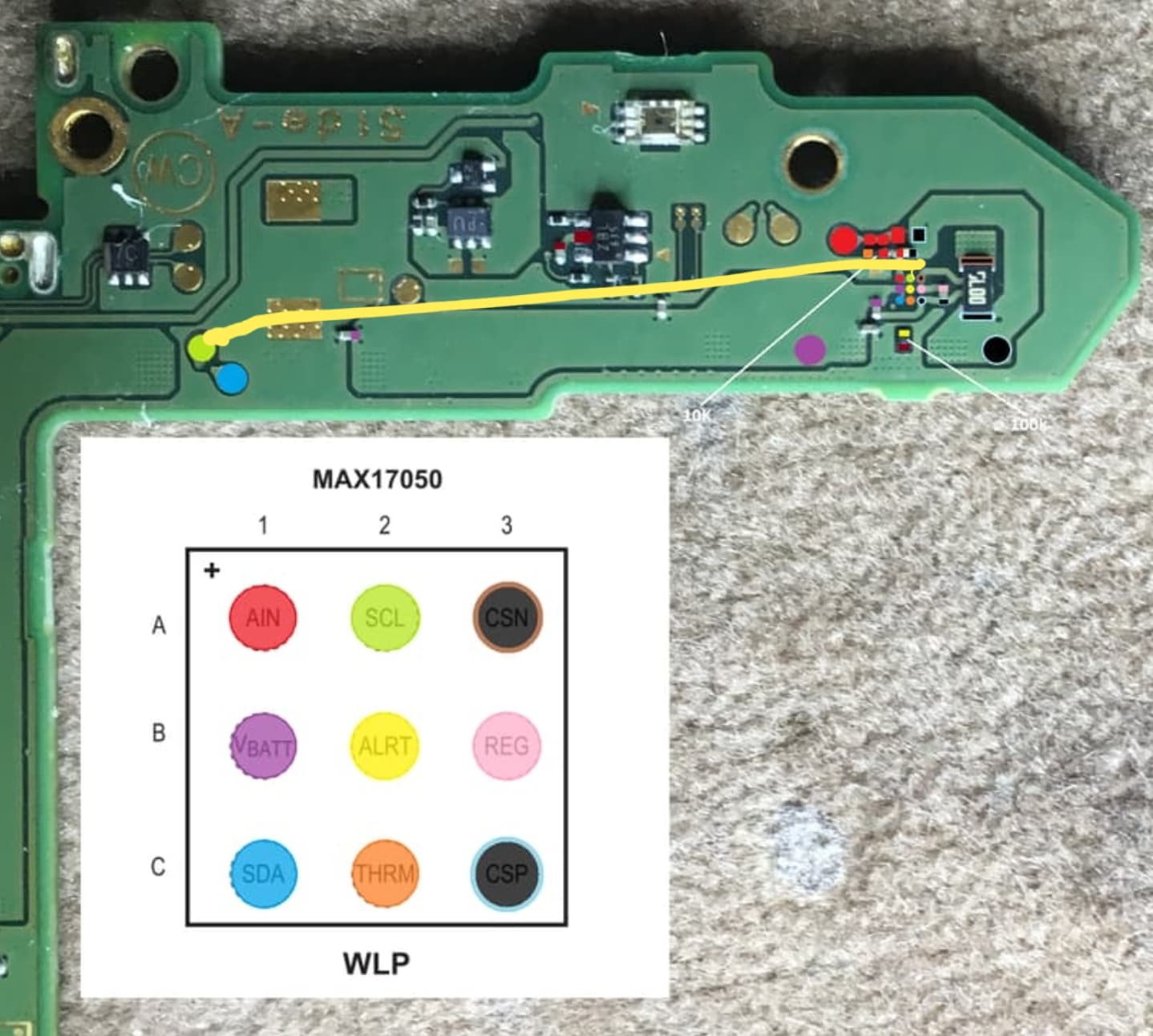
I therefore had to be able to check the points in the middle and unsurprisingly the green one named SCL does not show continuity with other green points.
It’s smell not good !!!, i dont have any idea how to fix it.
You’ll have to narrow down where the break is by checking continuity from the fuel guage SCL pad to the next nearest and seeing if you have connection, my image above is incomplete and I2C lines ishow up numerous places elswhere such as the BQ IC etc… so you’d check for continuity from the fuel gauge SCL pad to the BQ SCL pad, if you have it, then check that the BQ SCL pin/pad has continuity to the M92 SCL pin/pad, clean rinse repeat, if you find where your missing continuity then jump it with some enamel wire
I’d also caution relying solely on your meters continuity buzzer (and this includes the other other lines at the fuel gauge such as SDA etc) as if you board is suffering as a result trace/via damage then as a result resistance on those lines can increase but still be low enough to trigger your meters continuity mode, so make sure to check the actual ohm readout on the screen or use the dedicated resistance mode
Quit hard to tell using the board scans as the quality takes a hit in this area, but it seems there is two vias for these I2C lines coming off the BQ pins, they go through the board several layers and then split of in two directions, with the ones your interested in heading off to the fuel gauge… so you have two options, dig down in a safe are of the board (fuel guage side) where these traces appear and then run an enamel wire from that round the board and back to the BQ pin or use an increibly thin peice of enamel wire from the BQ directly to the SCL pad and UV cure and place the fuel gauge on top.
As I said though ensure the resistance of your other fuel gauge lines… if one via has failed then there will be others which either have or are on the verge of failing open.
If the SCL pad on the fuel gauge has continuity between it and the test pad marked in the diagram then couldn’t he just run a jumper from the test pad to the bq pin as those will be directly linked? As a test pad surely runs directly to the place it’s testing?
Unfortunately I have no continuity between the max17050 SCL pad and the first green dot mentioned in the diagram, that’s why I tried to find where this continuity stops. it turns out that I have no continuity between the closest point i.e. the SCL of the BQ. therefore I must link them directly. Wish me good luck
Yes in other circumstances that might work, though I think the line to the testpads comes from a junction from the suspected failed VIA… definately worth checking though as I only very briefly checked those blurry board scans