Hi everyone,
I bought myself a 2nd hand Switch to learn a few things as a hobbyist (I’m completely new to this). It was listed as “untested”, but that was obviously a lie: a torn ribbon cable for the backlight, some sharpie writings on the board, a sticker on the game card reader which reads “out of order”… I guess I’m going to learn a lot with this one
Anyhow, when plugged in, it draws 0.15A at 15V, then lowers to 0.05A. When pressing the power button, it goes to zero. When plugged in to a computer, it draws 0.46 at 5V. It’s detected by Windows, and even seen by TegraRCM as “OK”, but no payload can be injected.
I checked everywhere with my multimeter for shorts, bad filters, blown fuses, etc, but everything looks normal.
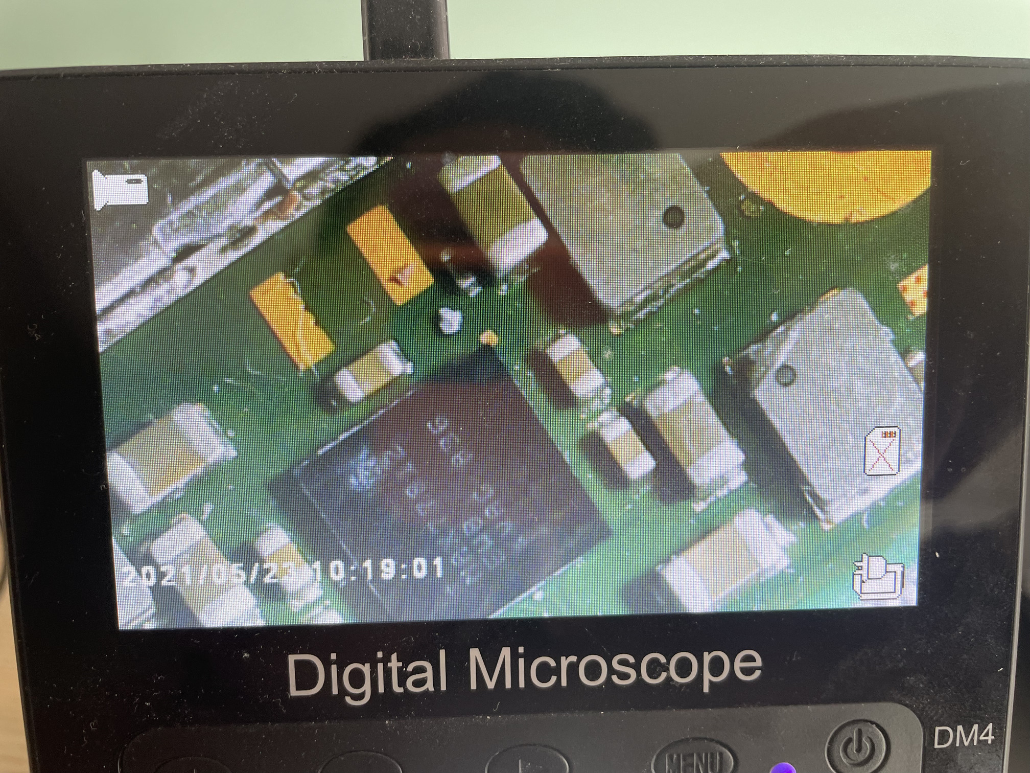
I followed Retrosix’s guide, and I found a lot of missing rails around MAX77620.
Stage 1 rails:
In your opinion, does that mean MAX77620 is faulty here?
Please let me know if you need more info or measurements, I’m very eager to learn.
Thanks for you help!
If tegraRCM is detecting the switch in RCM mode and you’ve not purposely put it into rcm mode then that is likely a nand issue or the switch has autoRCM enabled.
Try sending a payload to the switch, if tegraRCMGui shows a 0x7000 message then it sent successfully and the switch is not patched and may just have auto rcm enabled
Hi PhynxVT, thank you so much for your answer. I did try to send a payload, but the program hangs (“not responding”). I tried an online version, no success either.
Even if I were in AutoRCM, shouldn’t I be getting all the power rails?
I don’t believe so, though don’t hold me to that as I am not 100% sure.
Go plug your sn into xhttps://ismyswitchpatched.com/ this tool will let you know if you can load hekate. Good news here though is that at least its being detected by windows.
FWIW, to my understanding the 77620 is very sturdy and doesn’t often suffer failure on its own. If you are missing voltage rails on this chip as a rule of thumb id start by looking upstream of the issue before monkeying around with the max IC.
Have you inspected the USB-C port for any damage / buildup / overall wonkyness? I personally just had a board getting stuck at first nintendo logo that was due to one wonky pin in the connector. Have you inspected the fuel gauge (max 17050) and its surrounding passives?
Could really do with knowing what type of board this is as if this is a Mariko unit then this potentially changes things. Assuming it’s a standard Erista rev board
Should be present following prompt to boot. If theyre not you’d want to measure the resistance to ground on these rails.
So if it hangs from my experience it can be two things, a bad usb cable or a patched switch
With a usb plugged in check if you get 1.8v on the various vias on the nand module, your current voltage rails are expected, the 1v0 rail being 0.8v makes me think this is a mariko board? HAD-CPU-10? if yes then it is patched and your issue is the nand module
It’s hanging in this case because there is no Ram rail, Switch basically can’t do anything without memory. I’ve seen anyware from 0.8 to 1.2V on the boot CPU rail across all board revisions so don’t think that’s an indicator
This is what I get:
*1V0: 22.8 Ohms
*1V05: 61.7 kOhms
*1V3: 7.53 kOhms
The motherboard reads HAD-CPU-01 and when I check the serial number on @coda 's website, it says it’s patched. I wouldn’t trust the serial number on the shell too much though, as I won’t be surprised the previous owner swapped it.
As @PhynxVT mentioned. I’m pretty sure Mariko units are the only boards with the HAD prefix. So unfortunately you can’t run any payloads
This too also signifies Mariko.
Are you sure you haven’t got these two readings mixed around? 61.7K on your ram rail indicates a near open. Can you take a few photos of the board as I’d like to see if there is signs of any prior rework, sometimes people attempt USB or M92 replacements and inadvertantly dislodge Ram in the process. As far as I remember though the rail should still be produced regardless of whether Ram is present or not (approx 1.05v) but maybe it’s different on Mariko
Also,can you overlay the readings your getting on an image on all inductors surrounding the PMIC, resistance relative to ground with black probe on ground just so I’m sure I’m not misidentifying the rails your measuring?
If someone’s misidentifying anything, that’s going to be me
Here are the Voltages, Resistance to GND, Diode readings (red probe on ground), a picture of the front and back of the board
ht tps://drive .google .com/file/d/1yqzdUddcrkFMS6R5mhhebODR0vx0_pdo/
(remove the spaces)
Aha, so the rail you’ve labeled “VDD_CPU_1V1” is the Ram rail (secondary in this case) i was talking about, sorry my bad as it can measure anywhere from 1.05 to 1.15V on any given board. So it’s all good in this case. Off the top of my head all your measurements look good. The rail you’ve got labeled as “VDD_1V05A” I’m guesing the info within the brackets is from the datasheet “from VDD 1V3” ? if yes then it makes sense to not being seeing a voltage here as your missing 1V3/1V35.
So on Mariko boards missing 1V35 is pretty typical, it seems to to suggest something pretty early on in the boot stage is halted. Unfortunately it’s hard to be specific in this case as pretty well anything could potentially halt boot but I’l just throw a few possible or common ones - Fuel guage would probably be most common, CPU/GPU buck reg, M92 sometimes, Bent USB pins sometimes, Bent LCD pins, then we get even rarer but still possble, P13, audio IC etc
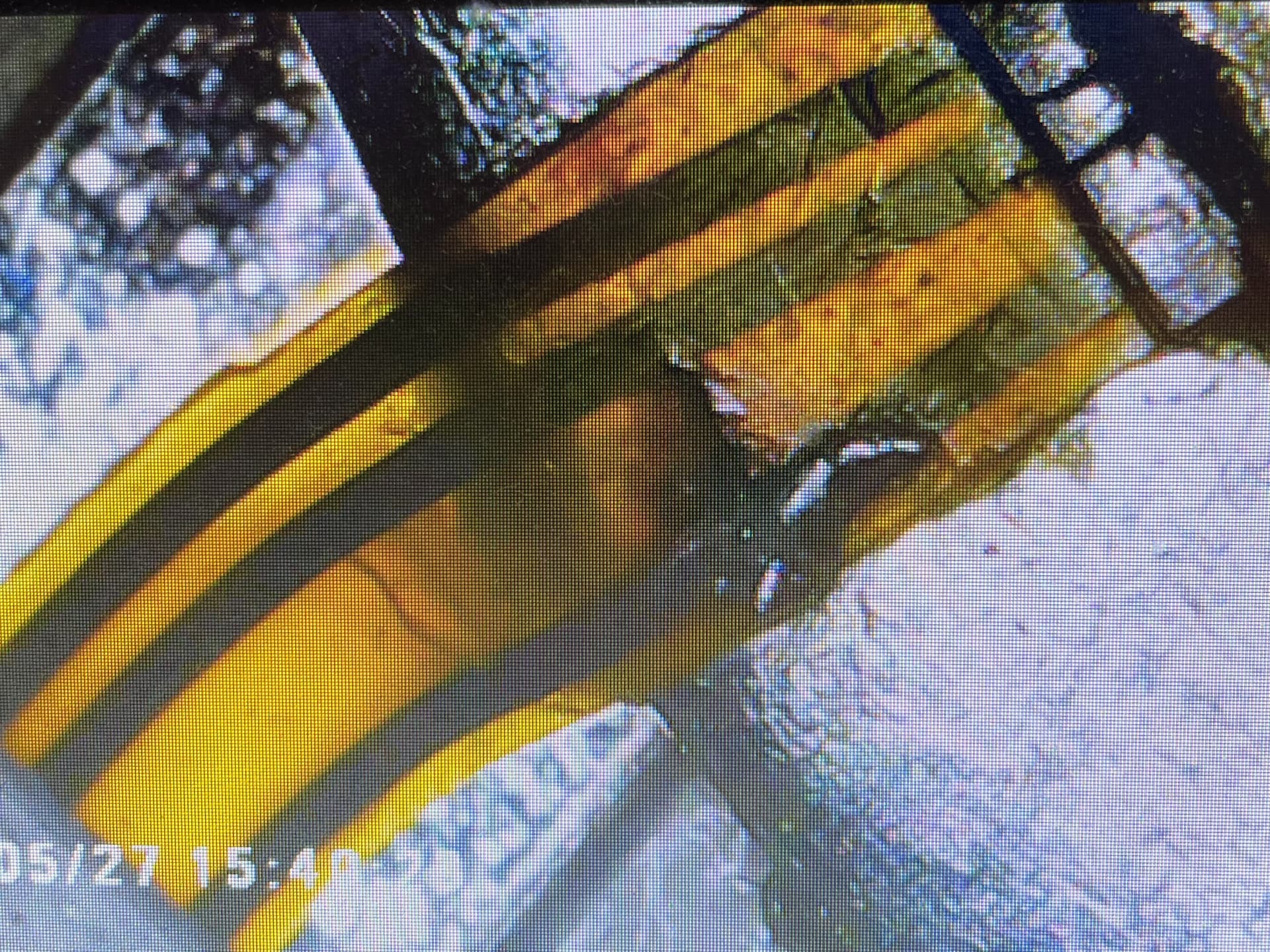
looking at your images of the board though everything looks in pretty decent condition, no signs of prior rework afaict, permanent marker is normal from factory… The only thing that stands out to me is over at the other Max IC below the SoC (CPU/GPU reg) it looks as though one of the inductors has chipped possibly indicating impact damage, it could well be this IC itself has suffered damage as a result and is causing the problems or a ball on this IC is floating… or worse some other IC on the board has either of those problems following impact - So I’d start taking a close look in this area to begin with, though I could be wrong and it could be camera//lights playing tricks on me
hard to say but as the damage at this inductor tracks with the damaged backlight ribbon (I imagine it sheared off on impact perhaps (?) ) then I’d say damage to the Max IC or it’s joints is the most likely candidate.
If it were me I’d swap out that Max IC and inductor (although I imagine the inductor is actually fine tbh) just to rule it out…but, It’s important to note I can whip off an IC from a donor and reball it and prep the board etc in a couple of mins and reball the old IC if it was never the issue to begin with for later use. If your just starting out or don’t have the tools (or a preballed IC if you don’t have the tools) then maybe this isn’t the best first step as you could potentially spend hours on this or cause secondary damage. Maybe it would be best to start with the fuel gauge (even though I don’t think that’ll be your issue) as theyre cheap and you can easily find them preballed etc but I think it’s up to you,
I don’t think it will be the M92 IC if you can’t see any signs of damage to the USB port and also because your rail checks earlier make it so much less likely.
You can measure the resistance to ground on the inductor surrounding the Max IC in question but given this is a suspected open scenario I don’t think the odds are stacked in your favour that we’ll see anything revealed specifically on the outputs.
It might also be worth looking very carefully at all these styles of IC’s (glass package style) and just seeing if there is any indicators of harline fractures or chips onn any of them, with particular attention paid to that Max IC below the SoC and the fuel gauge which might help narrow things down, though I imagine you will have looked for this since last time.
No, no random reflows, as if a ball is floating around under there, for example a ball sitting around SYS (just as an example) and some sub 1.2V I/O and a random reflow causes them to touch (and it’s sods law it will happen ) you’d just destroy the SoC the moment you apply power.
Oh, one thing I completely fogot about. Have you got a known good display to test in conjunction with this board? Or do you think your able to repair the backlight ribbon? (I have a post here somewhere going into detail regarding repairing ribbons of this style if your not sure)
As, while it’s unlikely, it might well be outputting a panic colour code on the screen which could further narrow things down. For example, if you were getting an orange screen it would further point towards that Max IC below the SoC or an SoC issue itself is the most likely problem. Just for example
And the plot thickens! I love this fault finding part, thank you so much for the detailed explanations!
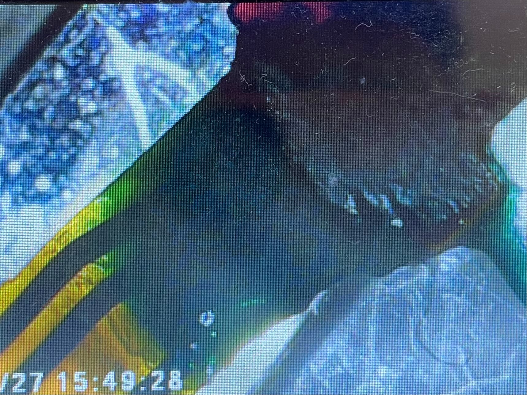
Now that you mention it, the ripped backlight ribbon and the chipped inductor are probably correlated, you must be right! The inductor is still conductive, so I don’t think it’s damaged
Never had to fix a ribbon before (I’ve always swapped them in Macbooks for instance), so any resource will be appreciated
Nothing else looks suspicious
I just bought another faulty Switch (because I make bad decisions). Hopefully, the display will be fine, and I will test the board looking for panic colour codes before going crazy with the hot air station.
I’ve never soldered a BGA, let alone reballed one. But I’m eager to learn and will try with preballed ones, starting with the fuel gauge then the max IC
I’ll keep you posted, thanks for your help!
topic here on the subject, different ribbon but same principles
It’s worth repairing them as the replacement LCD panels avaliable for Switch which while cheap are either the manufacturer casts offs much like the enviroment for phone screens which exhibit ghosting, colour patches and other similar issues or theyr’e refurbished with new ribbons bonded or soldered on (in the case of backlight) and that’s if they don’t turn up DOA and then you have the nightmare of getting the panels into the assembly square etc which is not a problem you’ll be used to if your coming from a macbook or ipad background as the fit and finish there is usually spot on and the frame won’t allow you to fit the panel crooked.
Just practice this elsewhere on some old phone or laptop boards prior to trying on the actual device of repair and get to grips with it. after failing the first 10 / 100 times things will start to take shape
Hey there,
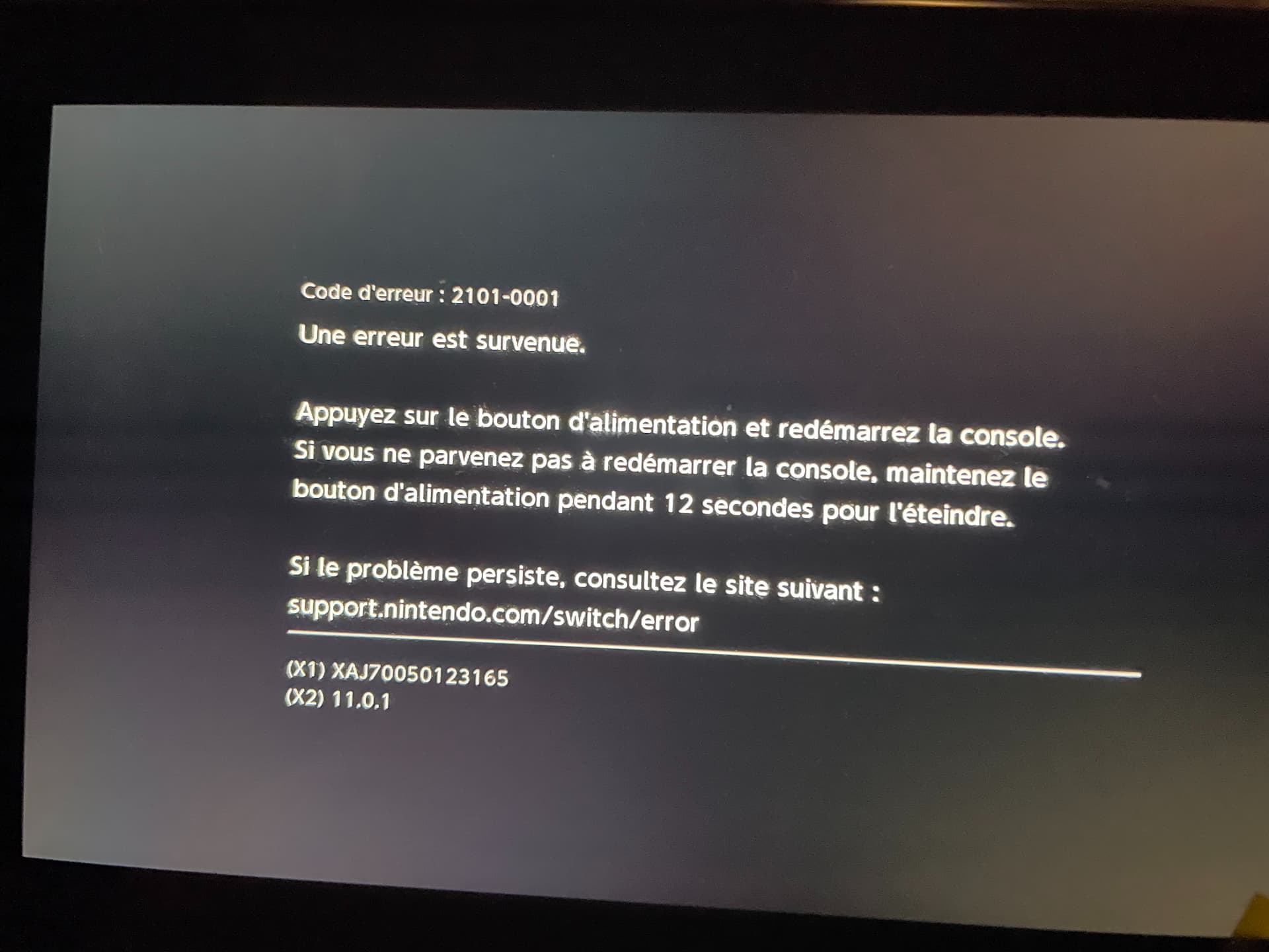
So first update: I received the other faulty Switch. It was covered in flux and the USB port had obviously been changed. The ammeter wasn’t even turning on, despite no short showing up elsewhere on the board, so I decided to plug in a charged battery to see what was happening. And it turned on with a 2101-0001 error. So as soon as I receive the new USB ports I ordered, I’m going to swap it. But I have high hopes to fix switch #2
Then I tried to fix the backlight ribbon on Switch #1. I carefully followed your tips.
Scraped some of the plastic