I don’t believe you suppose to have continuity between on end to the other end ( not a fuse)
Will double check later today for you
I don’t believe you suppose to have continuity between on end to the other end ( not a fuse)
Will double check later today for you
Thanks. A least i got the other cap back on with the solder iron.
Before you start pulling other IC’s off the board, please can you provide resistance measurements relative to ground on these “shorted” areas.
As we established earlier, one of your “shorts” wasn’t actually a short at all 
Hi Severence.
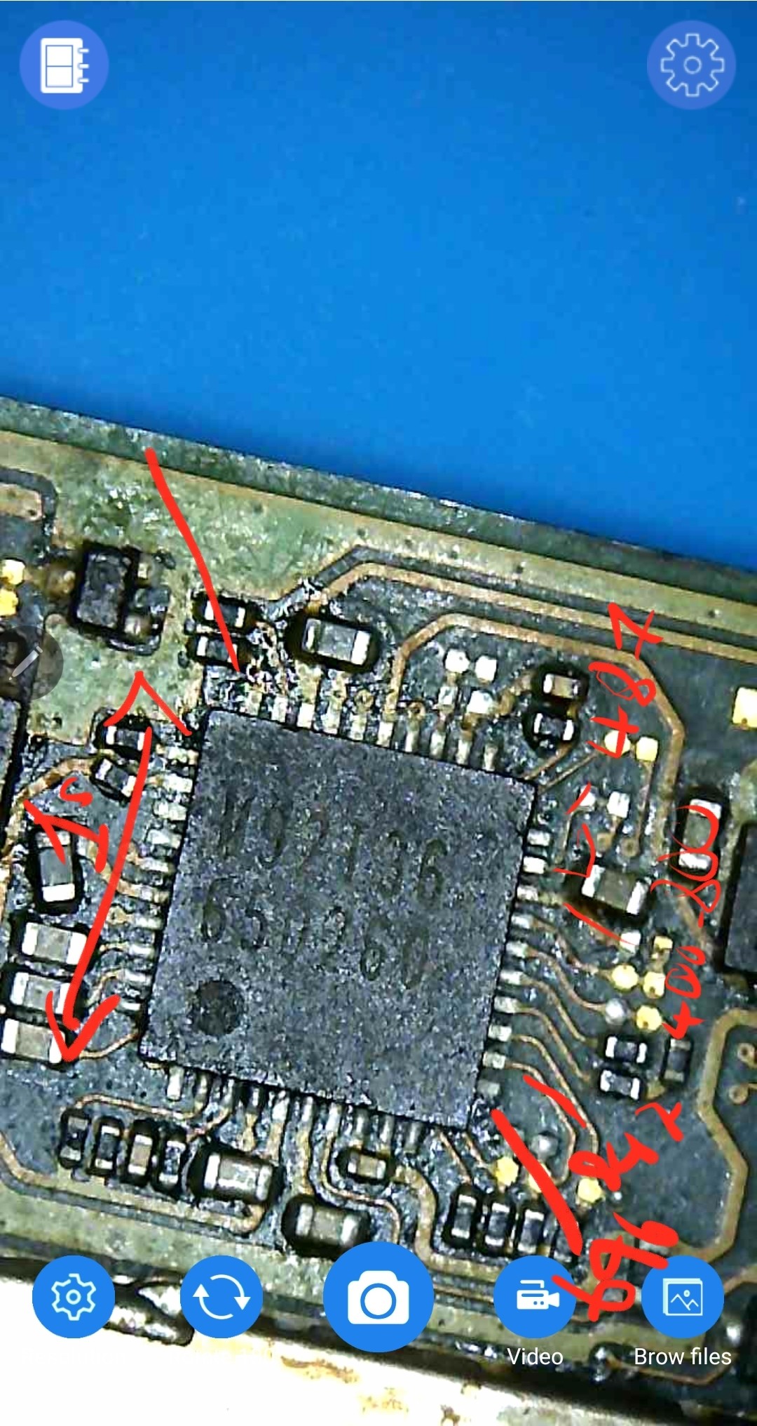
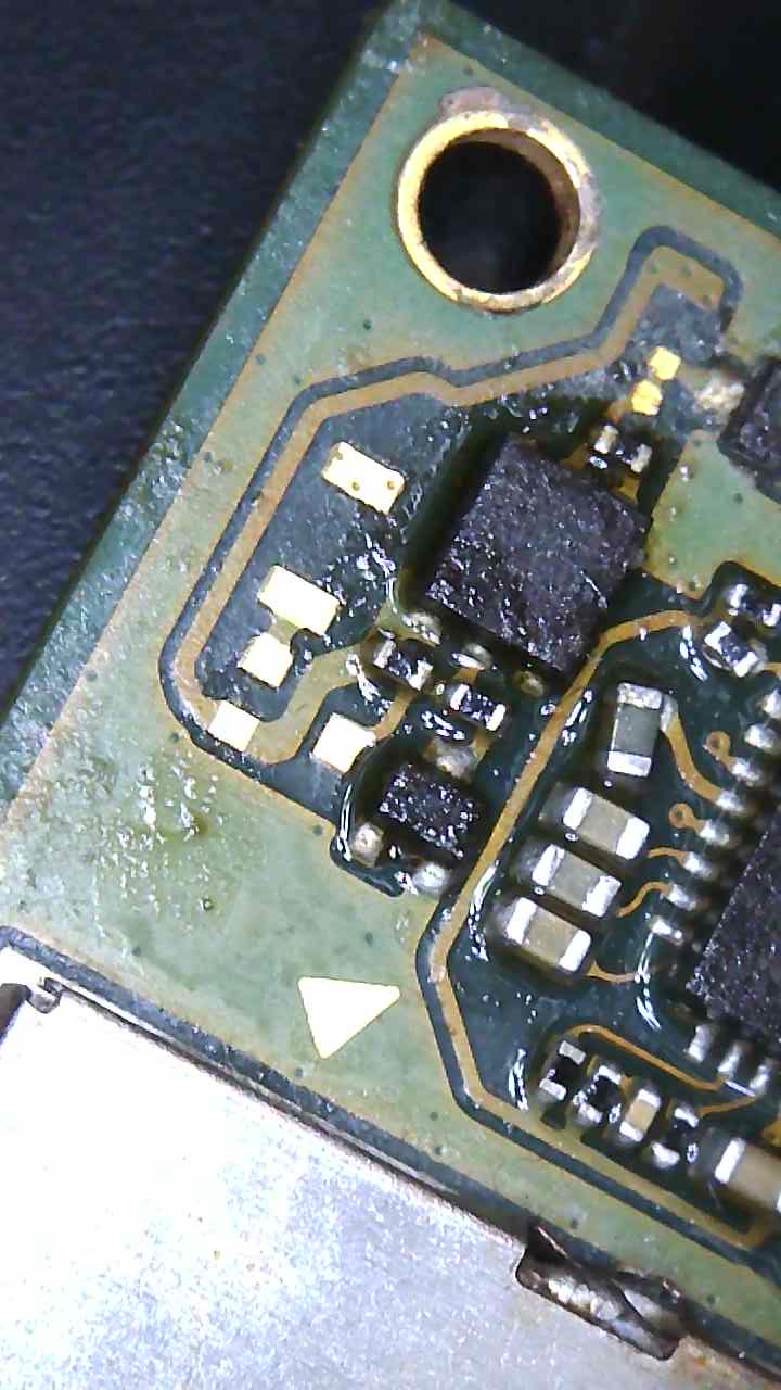
This is what I found. No shorts around M92 chip anymore but above present.
Btw will the switch function assuming all is well considering I seemed to lost/destroyed one of those tiny 100k resistors.
Your measurements pictured above are fine… no shorts
Probably not, I’ll measure it out of circuit and confirm the resistor value for you
Thanks Severence. I guess my understanding of what a short is flawed . Do I just put a new chip on and resistor (that should be fun) next?
Just to confirm your missing resistor is indeed 100k
Yep
No, your understanding is correct, it’s just a familiarity with those particular points and knowing what is normal and what isn’t…
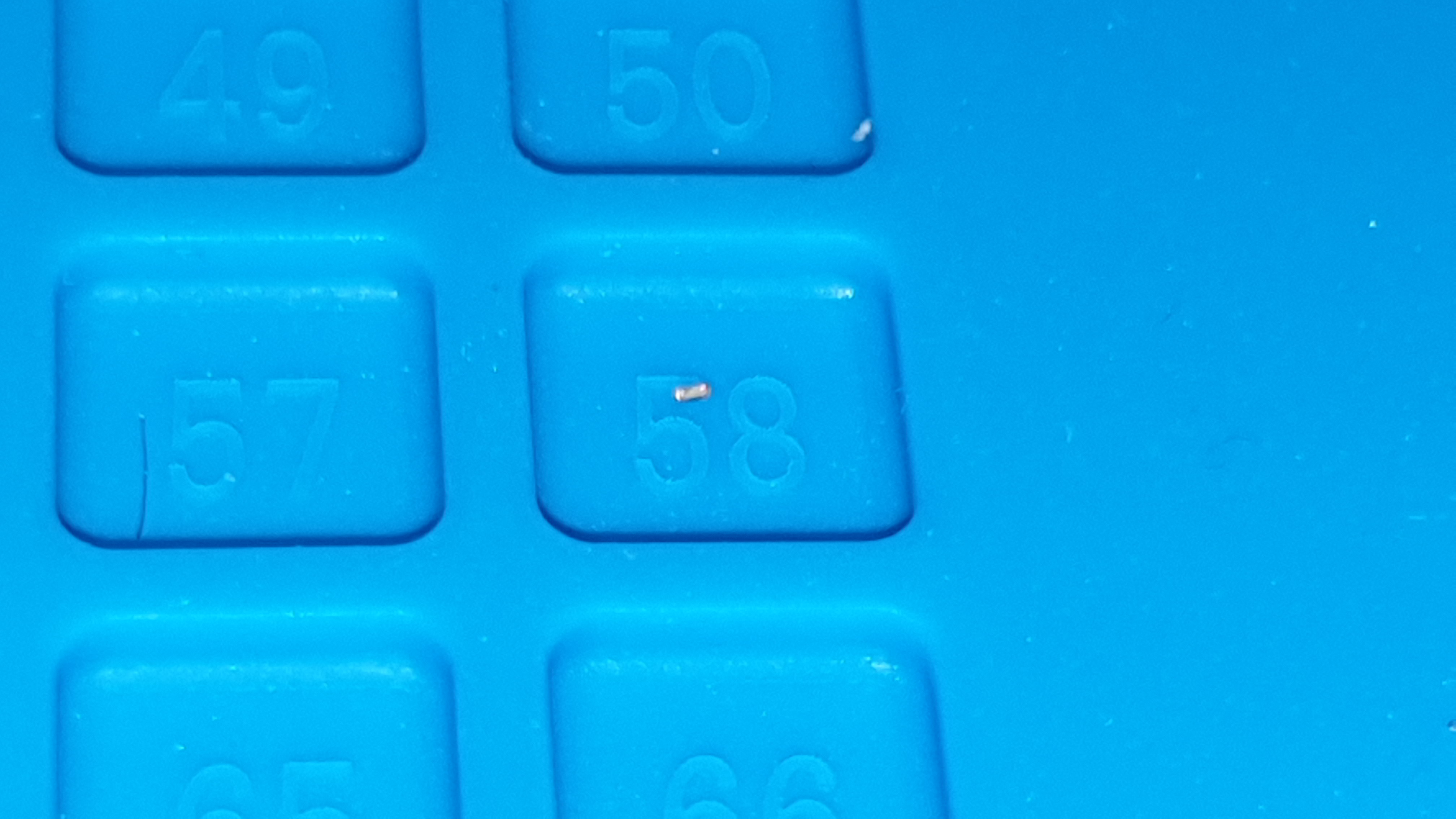
I actually found it haha its ridiculously tiny. I managed that to get on the other cap with my crappy magnify glass but I will need some of microscope for this job.
Managed to put the new ics fairly easily just to realign once but looks like it on properly. But that 0201 is nightmare. What’s the best method to put it on. Air or solder iron? So far I am tried air because I feel a solder iron I would be to clusmy. But it keeps flying away with air on lowest.
Unfortunately I lost again haha
So I’ve order a new one off Mouser amongst other suggested things.
Cheapo microscope is very ok but the image is yellowish here compared real life.
Hey,
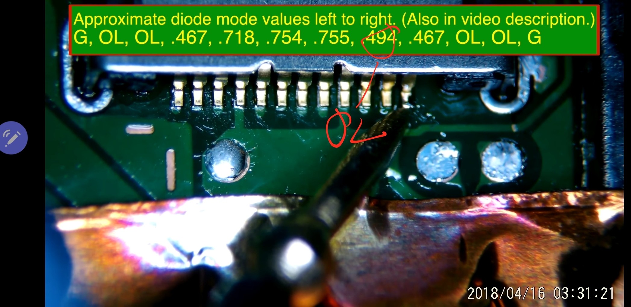
Apart from the ground and 2 pins in left middle. I am geting 0 reading and all the other pin on the m92 ic in diode mode. Is it possible this could be due to the chip not being solder on properly? Also the 100k resistor is still missing so i guess this could affect it.
Looks as though your lacking solder on the resistors pads, tin them up with your iron with leaded solder and flux (nice fluffly pillows) then add more flux, place resistor roughly in place and heat up with the nozzle directly above the resistor, if it’s significantly blowing/sliding the resistor around then your airflow is too high, decrease it. keep on standby with your tweezers in case it decides to tombstone.
3 resistors (good thing I bought a few)later I managed to get on although slightly wonky . New solder much better 
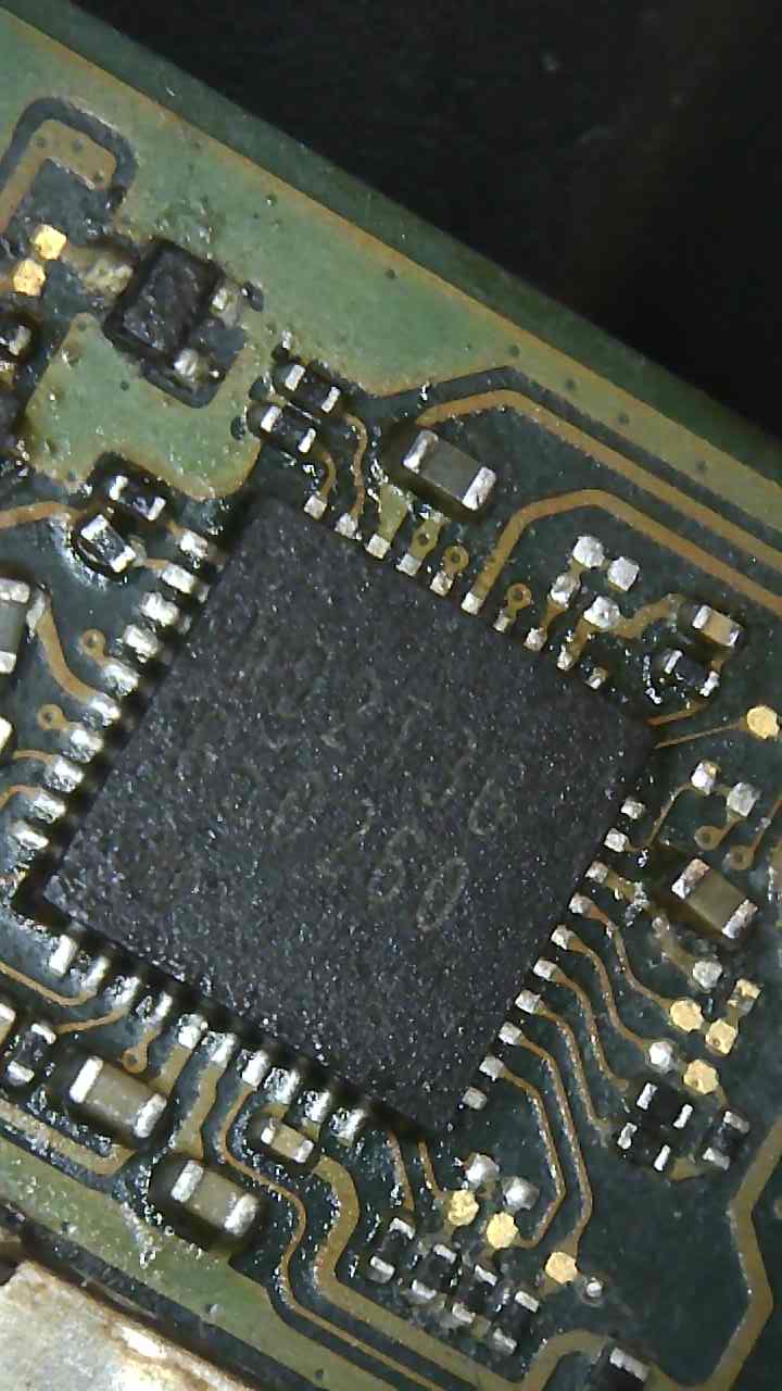
I actually took the chips off again and retinned with new solder and realigned it looks like it on properly but still nothing. Infact on the old ic I would get 0.02amp now 0amps. Also I took some dioade readings but some numbers are off and a lot 1s. I am thinking it’s not 100% aligned? Also waiting for new meter …
Possibly.
Check your battery connector, fuse, esd diodes too. How does USB look?
Which other two resistors were replaced? just checking, you used the correct values right?
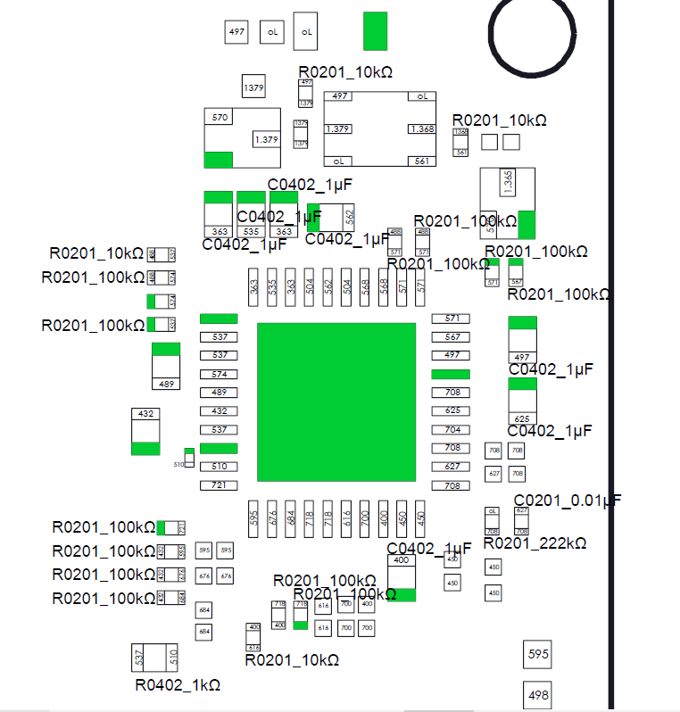
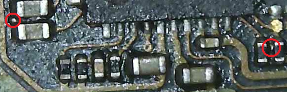
Btw few stray solder balls…might not matter as pads might already be connected, don’t remember off the top of my head.
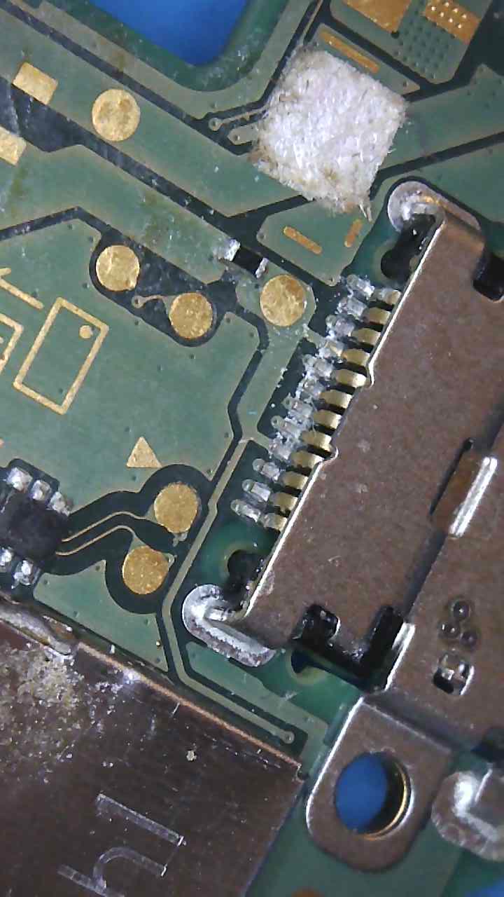
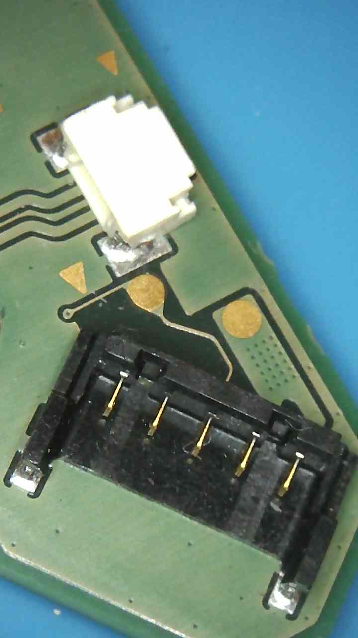
Taken some pictures of battery connector - any test I should do? Which is the esd diodes?
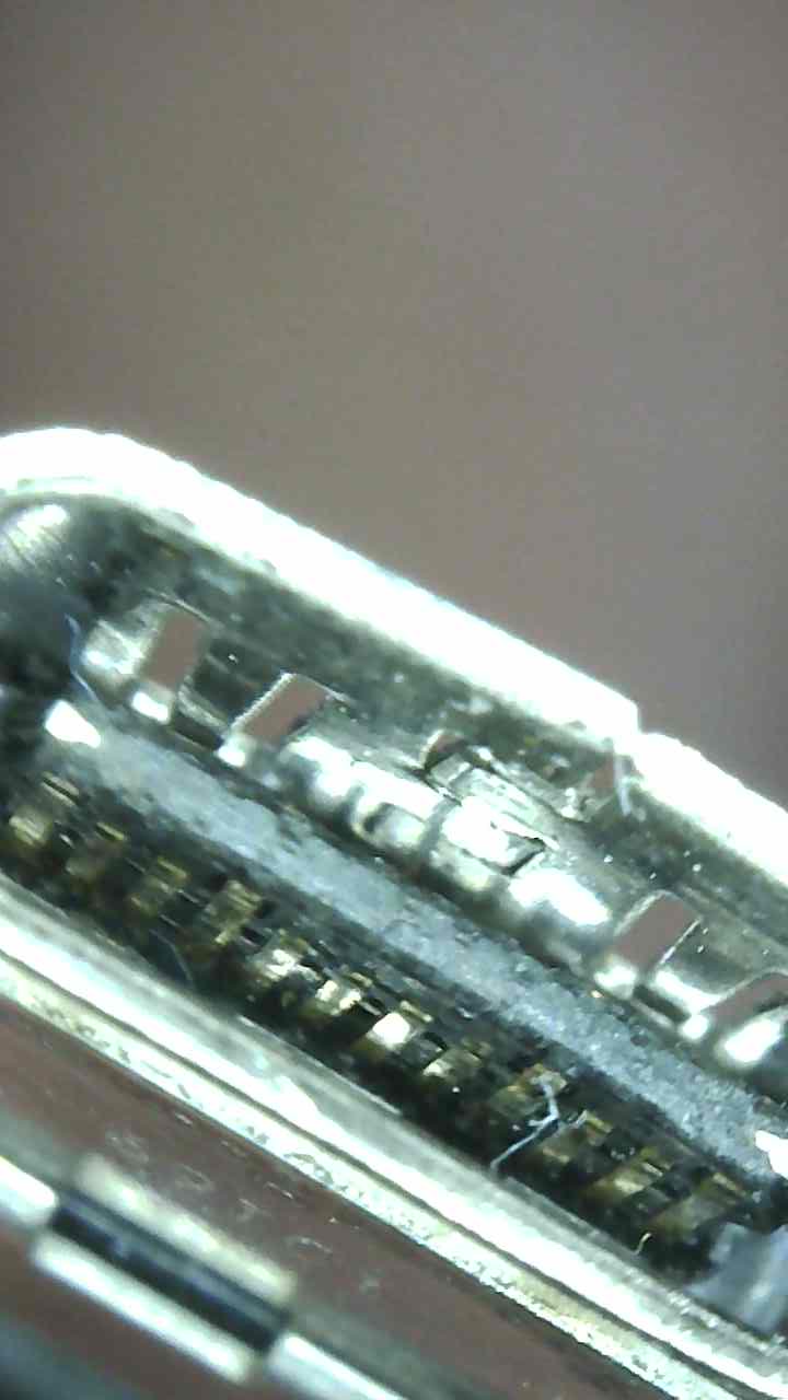
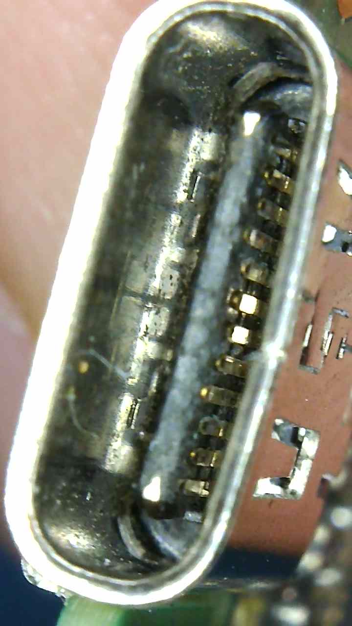
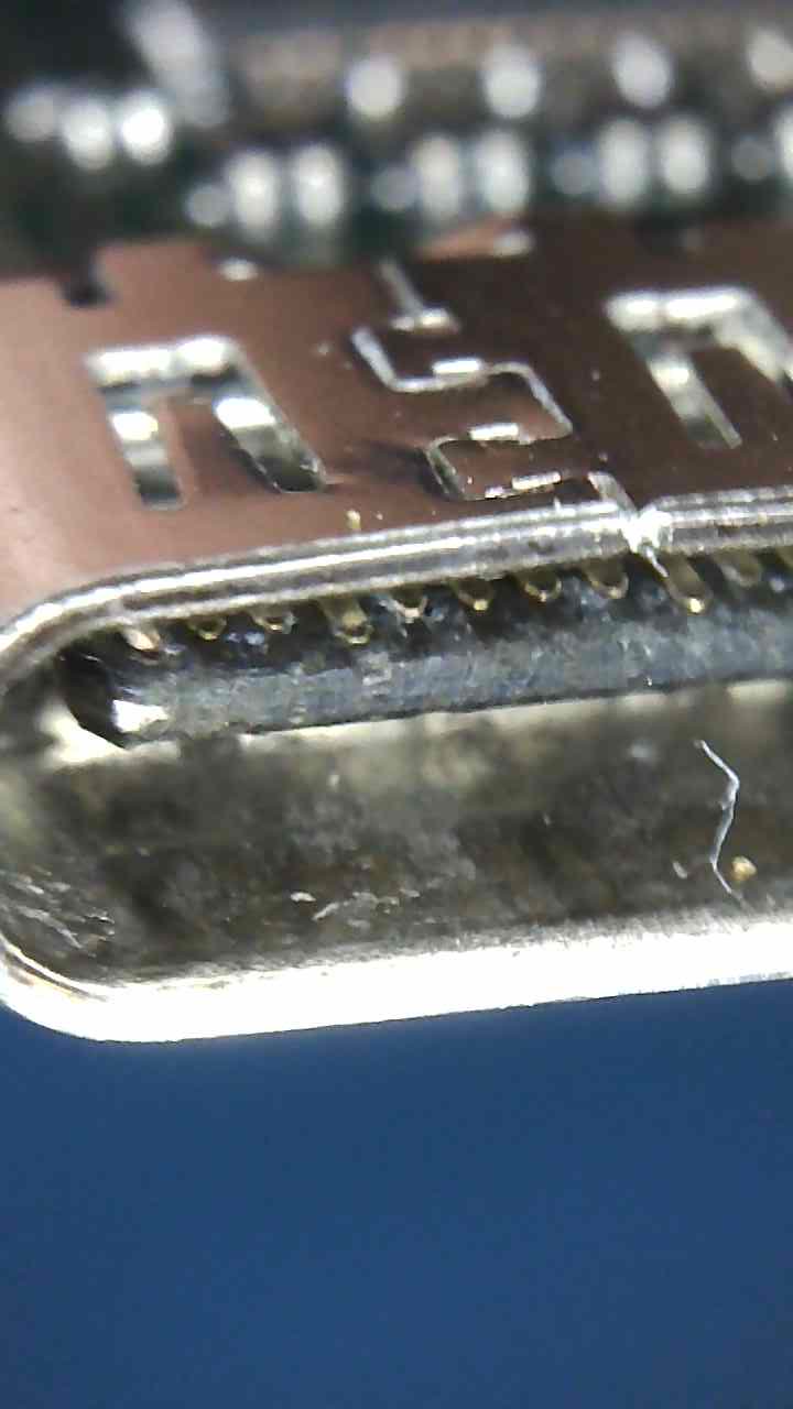
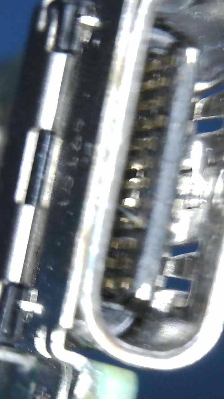
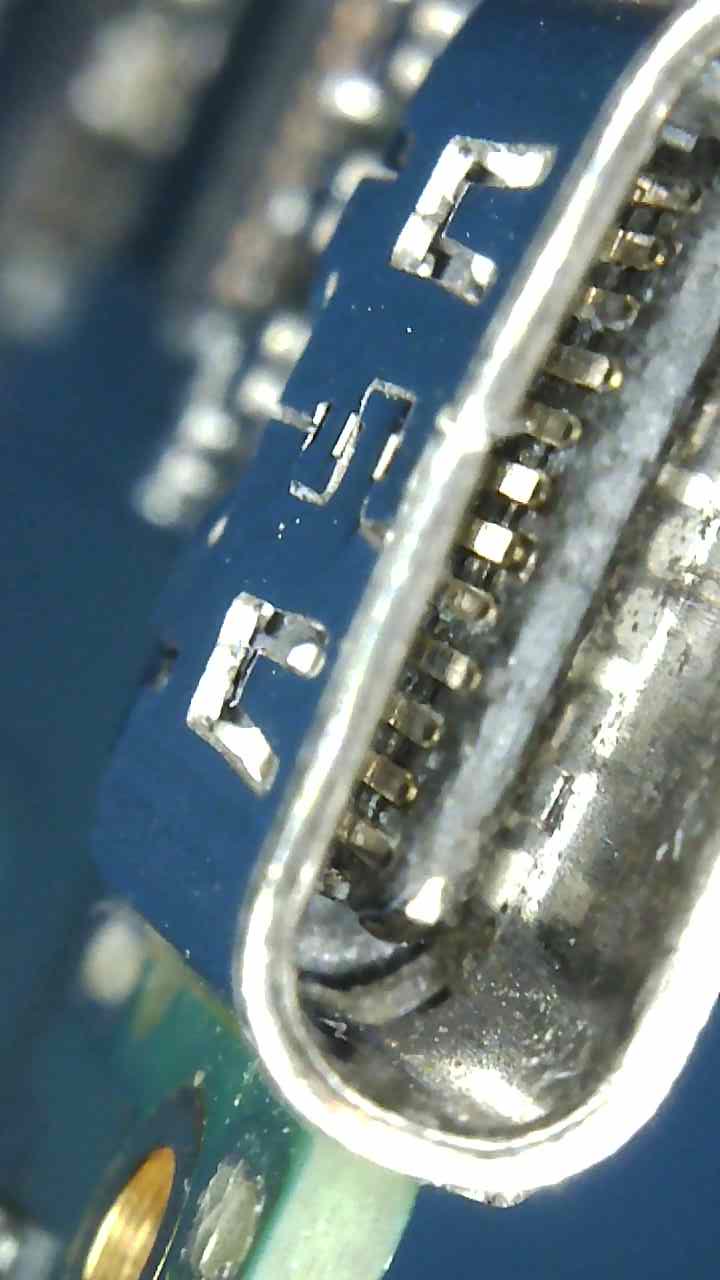
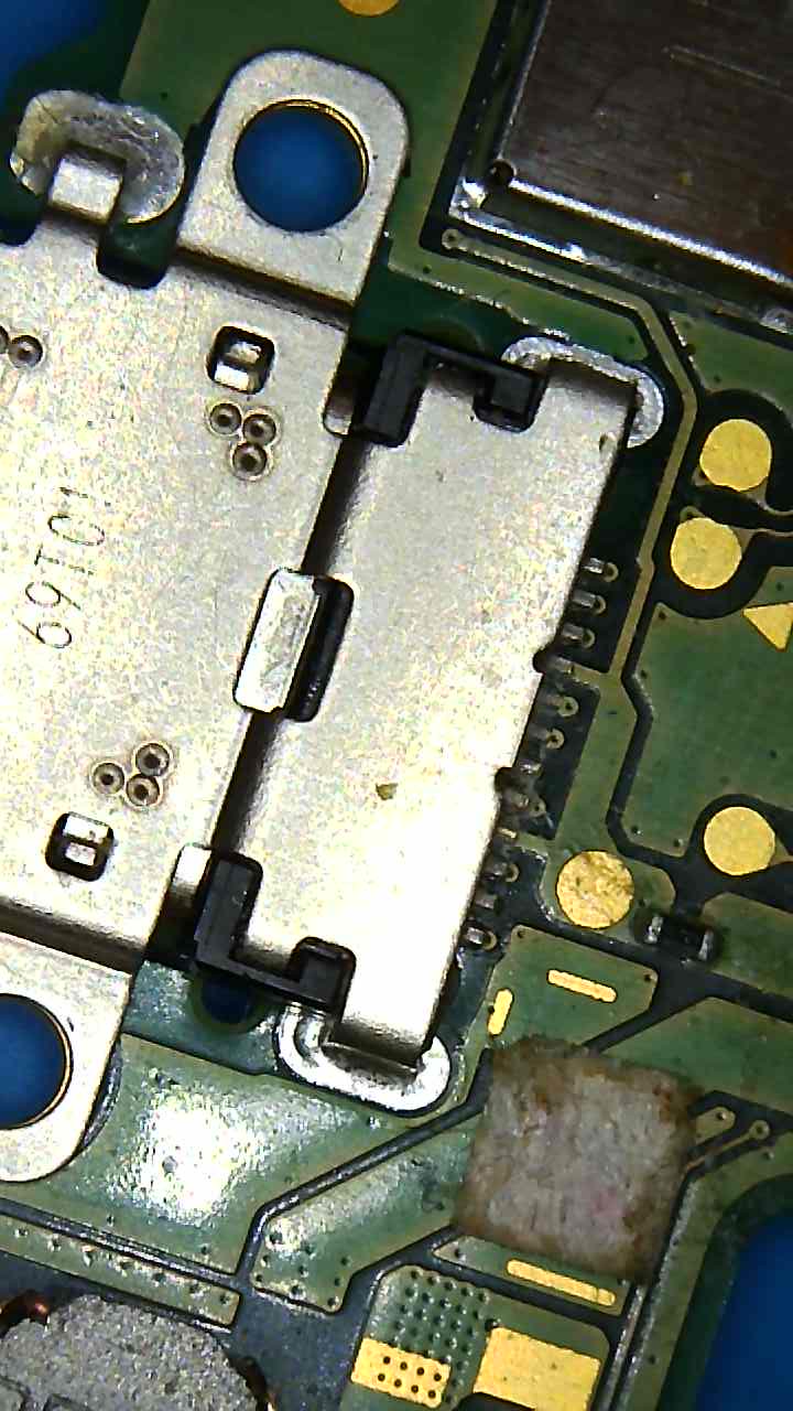
USB look ok, nothing bent, a bit dirty - pic uploaded.
Just one resistor - the wonky one ![]() But I lost 3 in the process. I order a couple of : CR0201-FW-1003GLF and
But I lost 3 in the process. I order a couple of : CR0201-FW-1003GLF and
Good spot on the solder balls - Managed to clear one the left and the one on right is lighting from what I can tell.
I returned the other meter to recoup on cost ![]() …waitng for the other one, so for now limited to what i can do.
…waitng for the other one, so for now limited to what i can do.
You’ll have to wait for your meter, just involves checking continuity to the next nearest point. Also worthwhile using another battery here for testing purposes so you can rulle out wire damage, they can disconnect from time to time (under the batteries sticker)
If you search the forum for “ESD diodes” in the switch category, there are a few posts detailing there location and how to test them in circuit.
Ah, i see ![]()
Looking at your images of the USB, maybe it’s the camera warping it, but it looks like the USB is bent slightly… assuming it actually has, thats typically as a result of pry damage with the cable connected, or a drop with the cable connected, in these situations the stem in the center can often break the conductors. You’ll have to test you have continuity when your USBC breakout arrives or just replace it
Take it your getting voltage at the fuse with cable connected?
Hey,
Yes I got ~5v near the USBC.
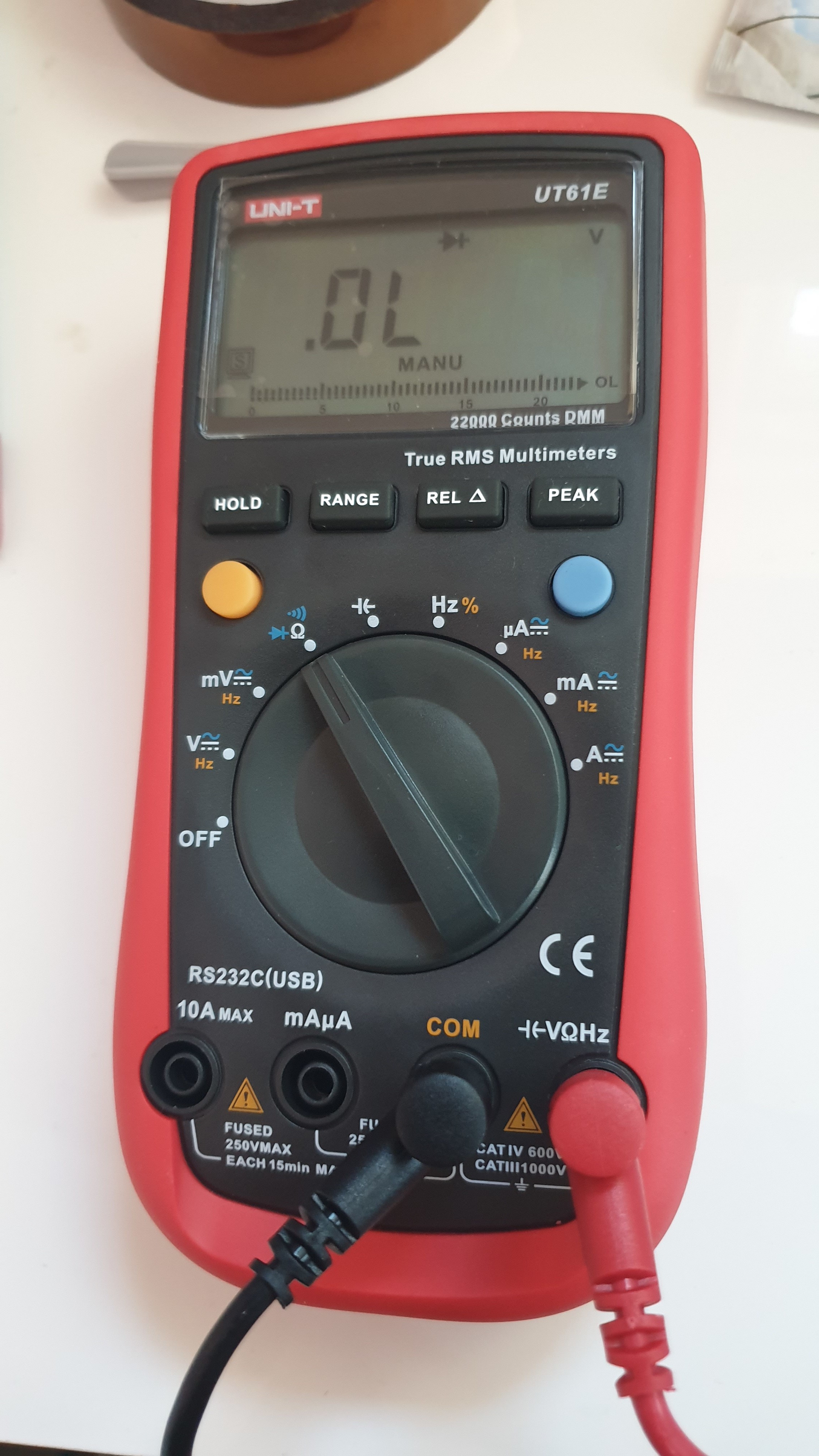
Got my UT61E. And made progress prehaps?
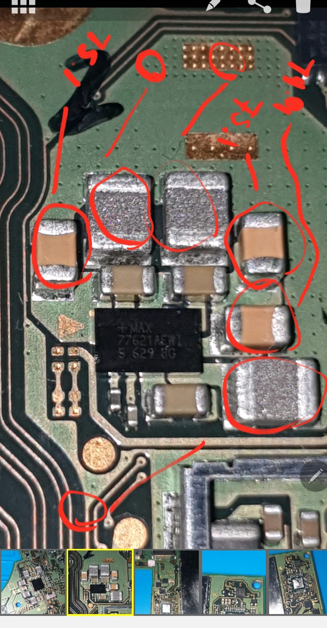
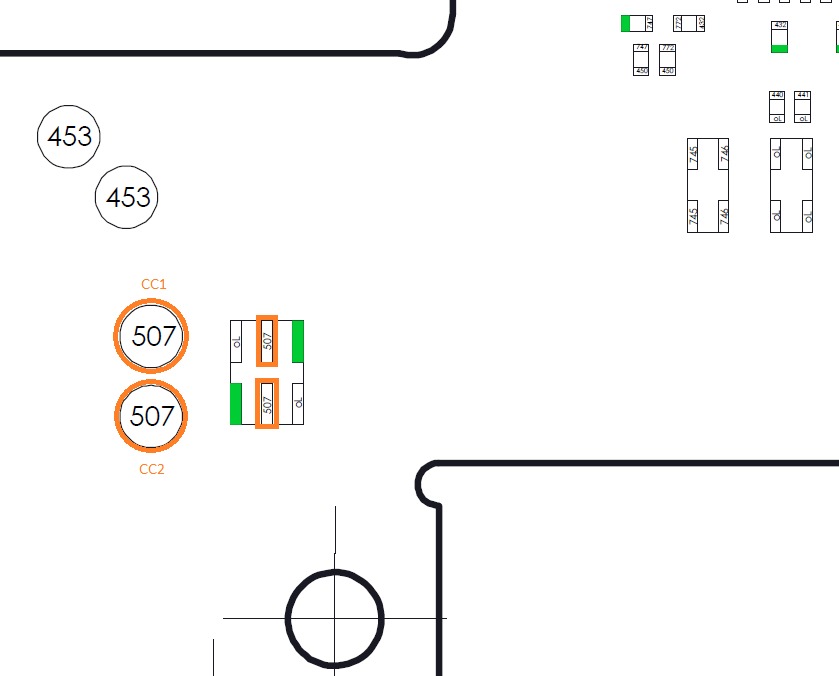
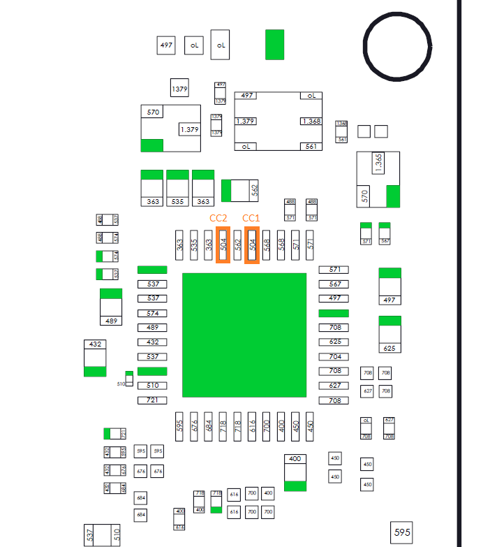
I looked up Calvins post about the esd dioades and I think I have problem here.
CCL1/2 and all highlighted orange give me OL . For reference the the points just above the CCL give a accurate reading but in different decimal 0.45.
Also I do have continuity on the battery pins expect pin 3 (middle). Pin 1 and 2 and 4 and 5 have continuity.
The small fuse by the usbc have 5v measuring while plugged into mains.
Thx