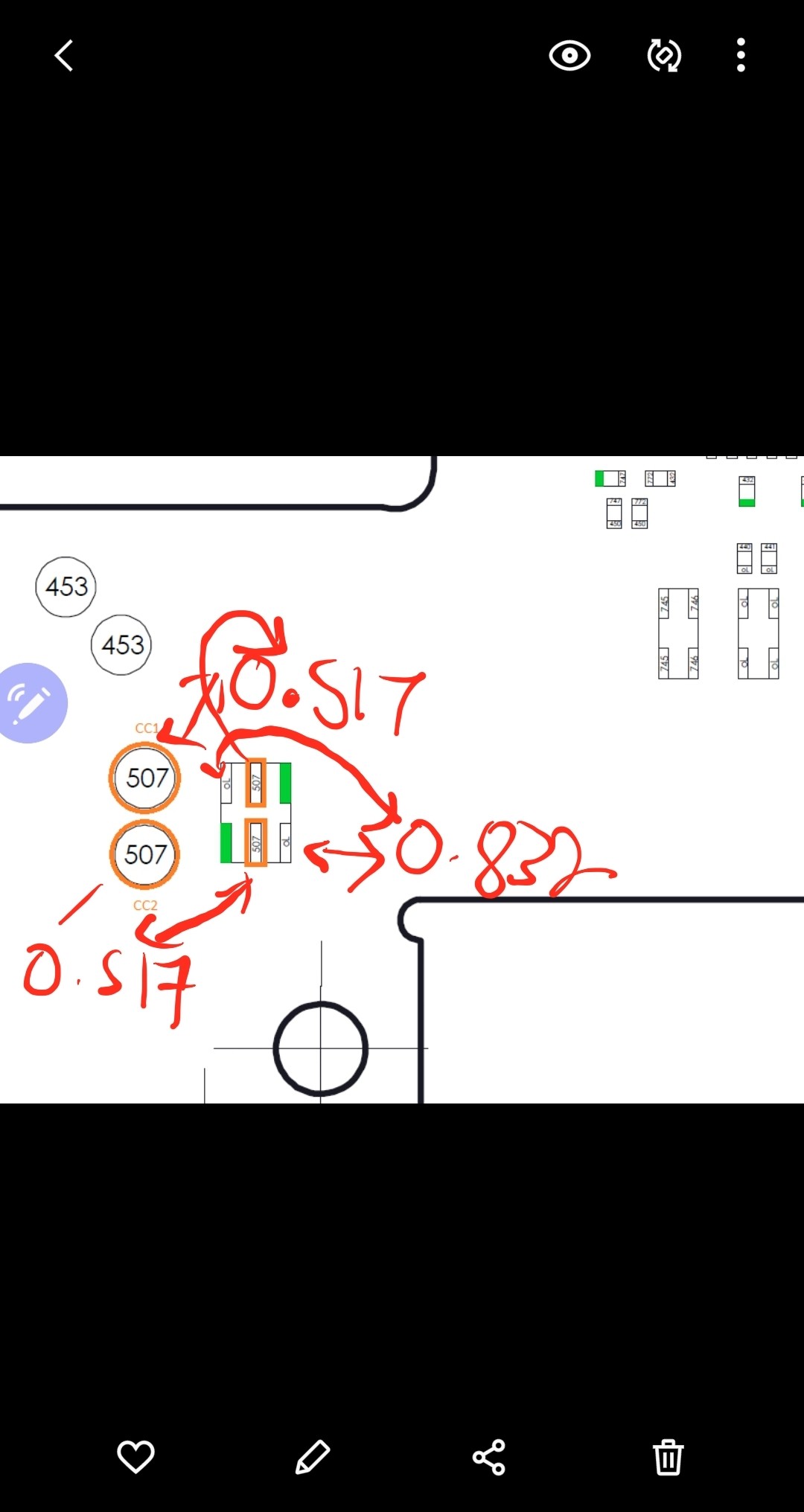
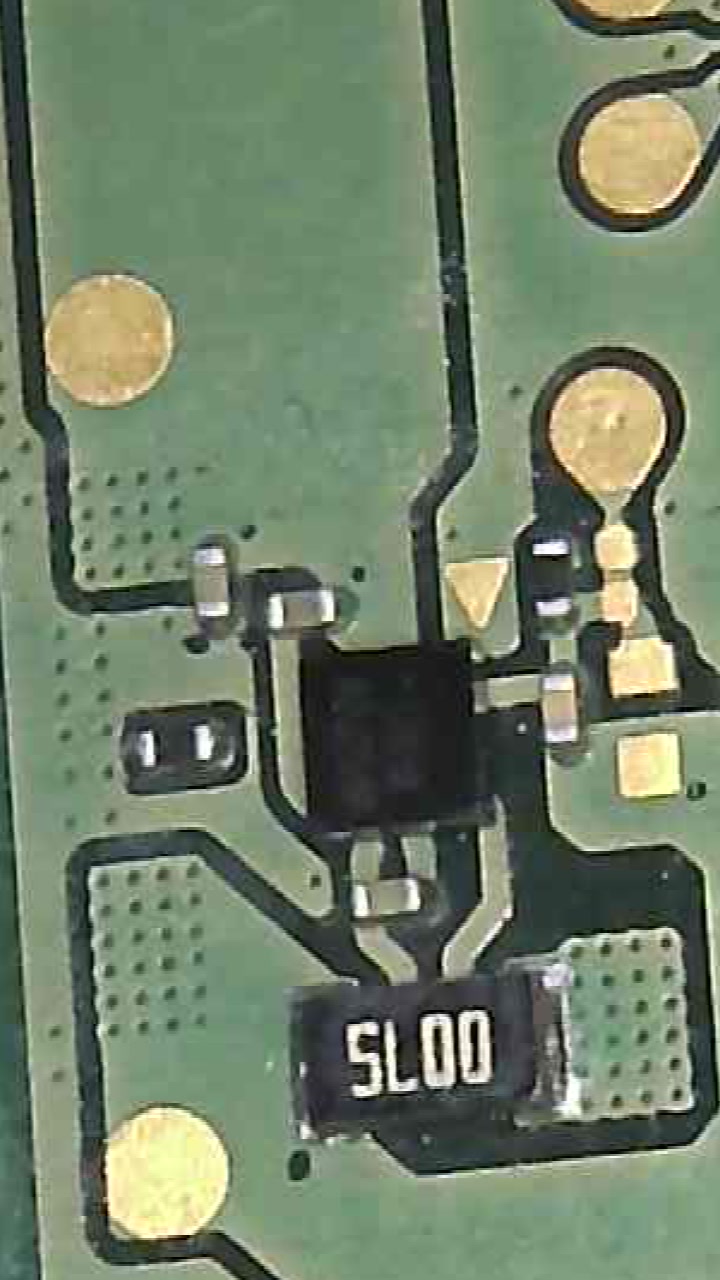
These points on “Side A” go directly to the M92 IC, you should be measuring approx 1.2 and 0.5 diode mode depending on probe polarity.
The points “Side B” go via a filter.
This indicates your M92 IC is still bad, or one of the pads is not making proper contact with the board, or something surrounding M92 is open or not connected. Check and see if you have continuity from CC1/CC2 to any of M92 pads.
Do you atleast have continuity from the pin to the testpad snaking off from it? it will typically measure in the high megs relative to ground, which is normal, it goes off to the fuel gauge.
Edit: whoops missed Calvins post there, doubled info, will leave it anyway
solder on is ok I have no continuity on both orange points. I will desolder completely with wick and put fresh leaded. I actually got m92 recently but i have another spare if that fails.
I’ve never tried, but you may be able to test the pads directly on the chip itself in diode mode, one probe on the center pad, maybe somebody else can confirm.
And just to clarify, you should have continuity regardless of whether M92 is present or not
It might be normal, the center pad might not be grounded until it’s soldered to the board, it might mention this in the datasheet but i haven’t checked, will take a look later.
Alternatively you could try using one probe on a pin you know for sure is ground from the datasheet.then reverse polarity.
I’ll check this for you in a bit on one of my IC’s laying around and see
I don’t know if the M9 IC i picked up was suffering any faults, but it does appear the center pad is isolated when off the board.
Diode mode doesn’t show anything conclusive, nor does resistance mode, black probe on ground (pin 1) and red on CC1/CC2 i measure approx 4M and 3M don’t think that helps particularly in determining there condition externally… unless the IC i picked up was faulty
I’ll maybe try again on a known good M9 IC… if i can find one hanging about the place
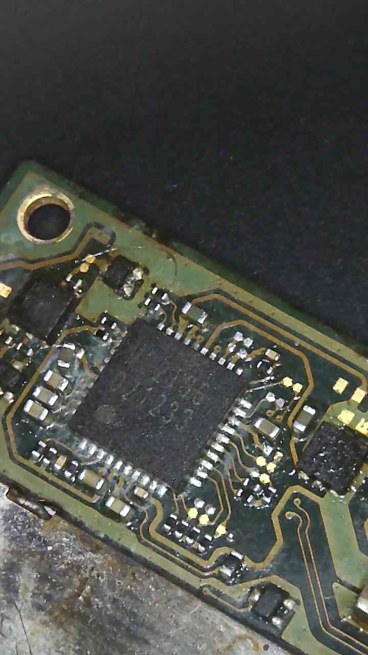
I put on another m92 that I have the other switch lite I am fixing. In the process of desoldering with wick I nearly pulled a pad off but I managed to push back down and dioades reading indicate it ok.
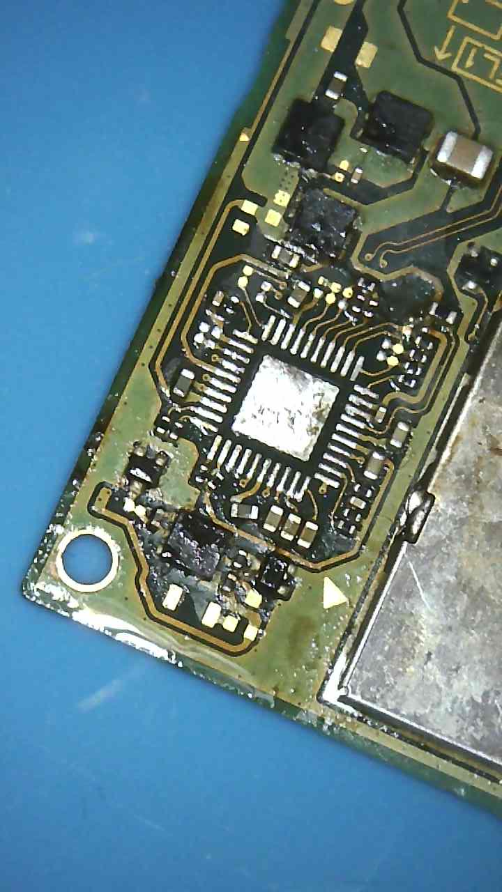
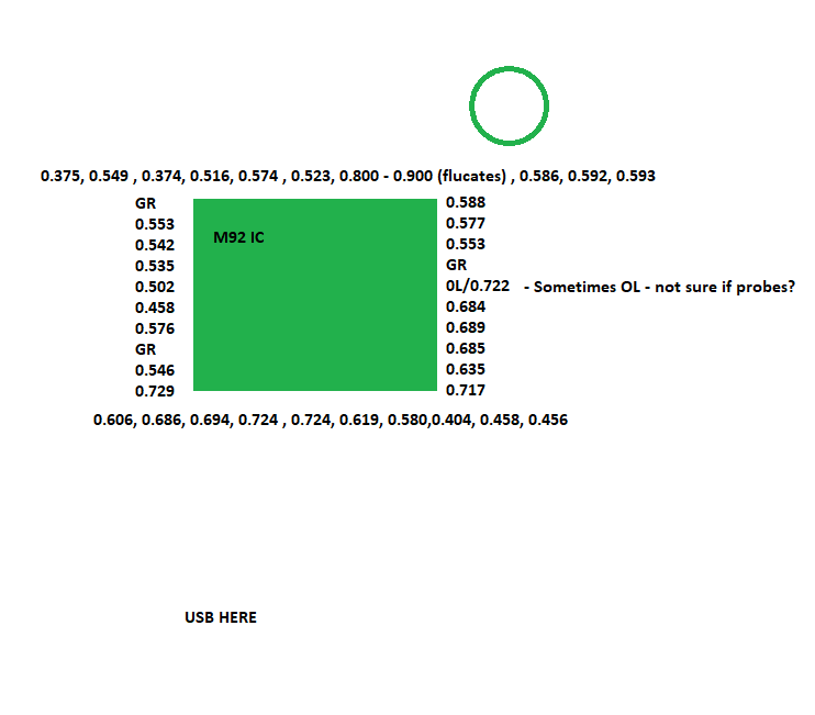
So this m92 has a bit more progress as I am getting all the required on esd dioades or close. But as you can see I don’t get 0L on the ones you would expect to get.
And even the dioades readings on m92 are almost all accurate expect the one highlighted red which has a ground reading. I got 0.02 to 0.05 amps . But it doesn’t boot. Why you think I might have ground reading on red? I made sure there is no bridges and proper connection.
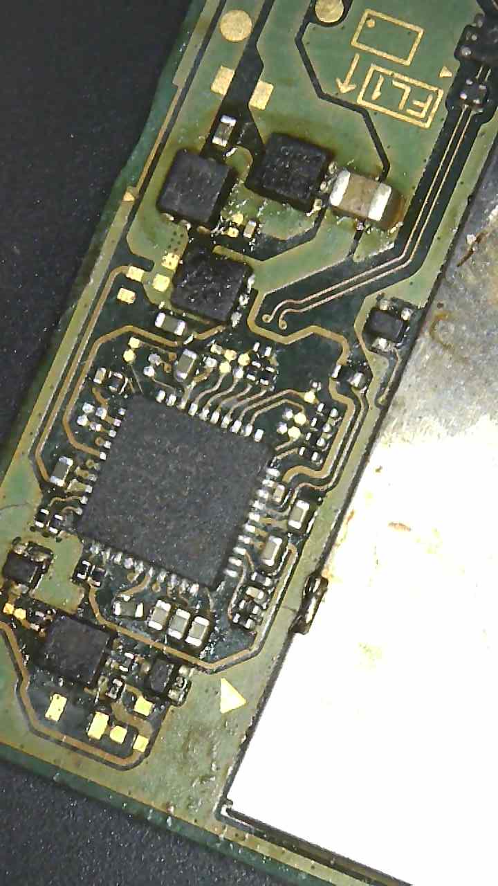
Pin 2 highlighted in your image:
According to the datasheet (assuming it’s correct)
VSTR/ATST2 TEST/Debug
Not yet looked into it or traced it out, bear with me…
Looking at the datasheet, it goes off to two 100k resistors i guess you bridged one accidentally during reflow maybe or the pad? I’ll take a closer look on one of my boards.
btw We still need to confirm your battery connectors middle pin, resistance to ground.
Will do. Am also in the process of doing a accurate dioade reading for the whole ic. I think you right about the resistor I knocked it out again when I touched up the solder haha. But it is back in place just need to finish the readings when I get a chance.
That’s not good if thats 16.7Ω … assuming there is no other issues relating to the M92 IC with your diode readings compared to Calvins diagrams, then next port of call is BQ and fuel gauge area.
If I’m interpreting your M92 IC diagram correctly, you now seem to have resolved your short on pin 2, correct? if yes, what was the problem out of interest?
btw for future reference, it’s not neccessary to wick the pads on the board after M92 IC removal, the only time this would be needed is if you were using a stencil to pre-apply solder paster on the IC directly… Or if you accidently added to much solder to the center pad and needed to remove the excess. Under normal circumstances, a few passes over the pads with leaded solder is enough to remove the majority of the original unleaded solder and prime it for a new IC.
I figured the BQ might be the next issue. I was looking at another of Calvins diagrams for the BQ and I wasn’t getting anywhere close to the voltage in the diagram earlier today.
Pin 2 was probably fixed by moving that 100k resistor. It was touching the other 100k resistor.
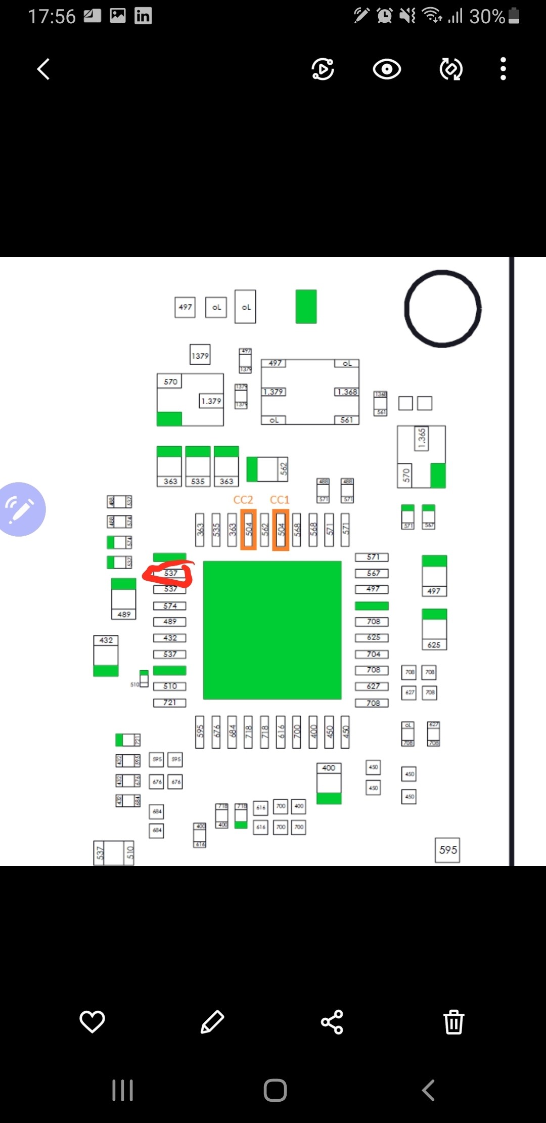
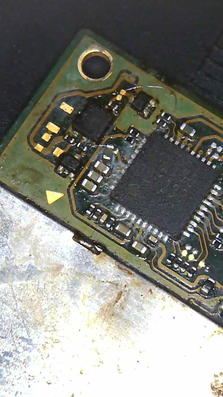
Lesson learnt about wick…nearly pulled off the pad on 4 from the right bottom.
Unfortuntely, still there @ 0.854 where it should be OL - Red on ground. I wonder if I need to make sure the pins on M92 are soldered properly. Because initially one of CC1/2 wasn’t giving a proper reading until I touched up.
I hope so. haha I will not plug it in but isn’t there a voltage check to make?
Yeah strange, these diode pads on the board are NC… they don’t go anywhere, so it’s either a bad diode or a bridge somewhere on M92 IC. If you remove M92 IC again, check those same points at the diode are open.
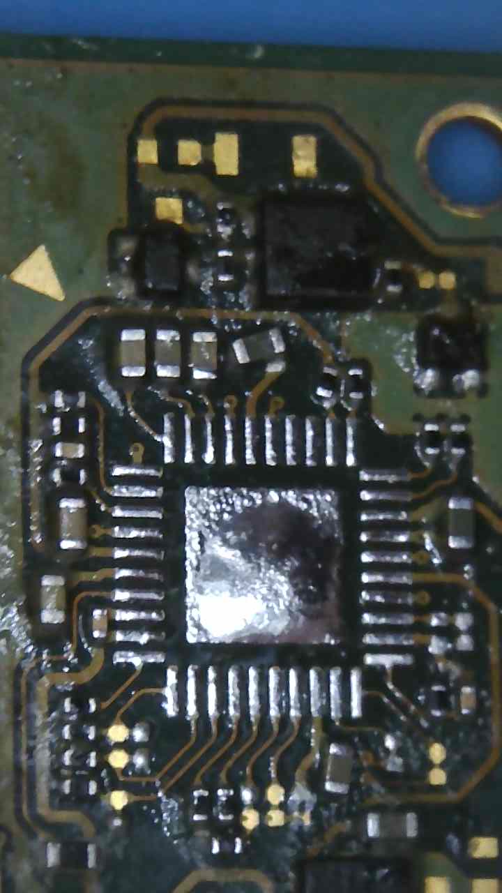
Btw looking at your image earlier of previous M92 removal, on the board you seem to have too much solder on center pad, wick it up so there is < half that amount (use hot hair to help if iron and wick are struggling). Upon reflow of the IC don’t push it down.
Add flux to your wonky caps and resitors during the reflow process of the IC, they should all fall back into place and properly self align
Also, I missed that on your diode chart, but your “0.900 (fluctuates)” pin is likely a bridge somewhere, just guessing, given it’s close proximity to that 100k resistor you touched up, seems likely.
Maybe before removing the M9 IC once again and putting this board through any more abuse
Set you hot air to 200C and hover in this area and run over this side of the IC’s pads with your iron and get them looking as clean as possible, if the fault on that pin or the diode doesn’t clear, flux it up again and attempt to reflow and nudge and see if that resolves the problem

 !
!


