Not*
Will attempt clean up all sides then reflow if that doesn’t work.
Not*
Will attempt clean up all sides then reflow if that doesn’t work.
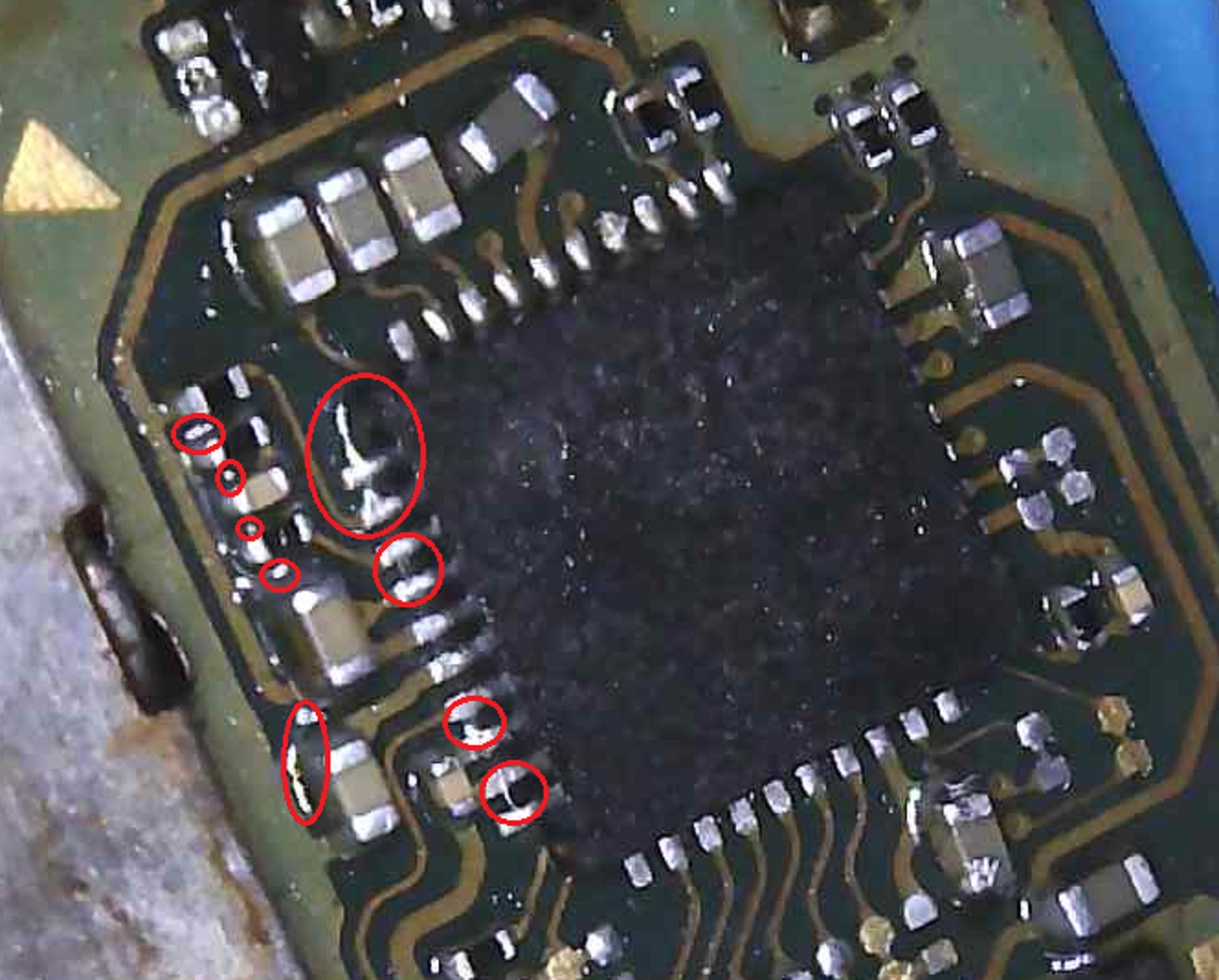
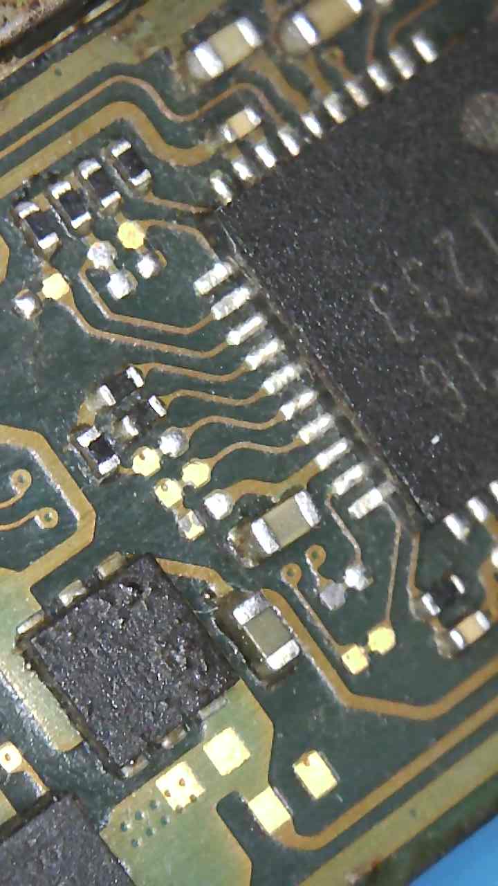
That’s just probably ipa or flux and lightning defo not bridges. This image should be better
I did get it a nudge towards the usb port but nothing changed. I think tomorrow I will remove off the centre pad. When I put it on the first time I did get a solder bubble which I cleared but I guess it could be bridge under as well.
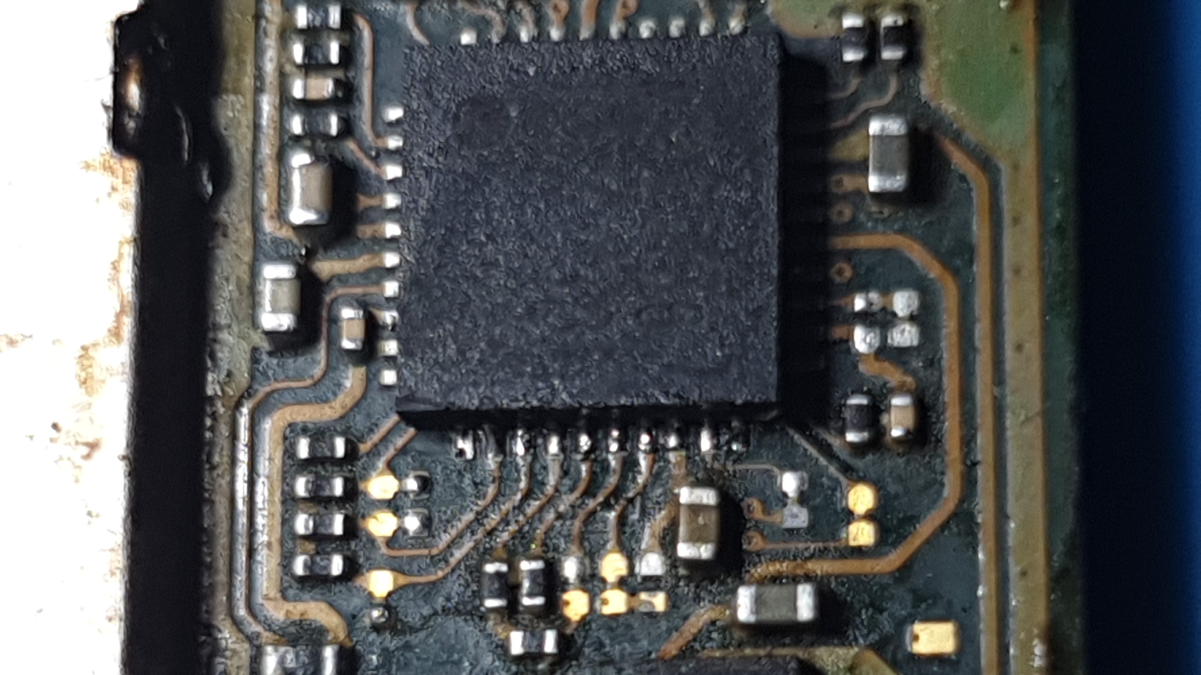
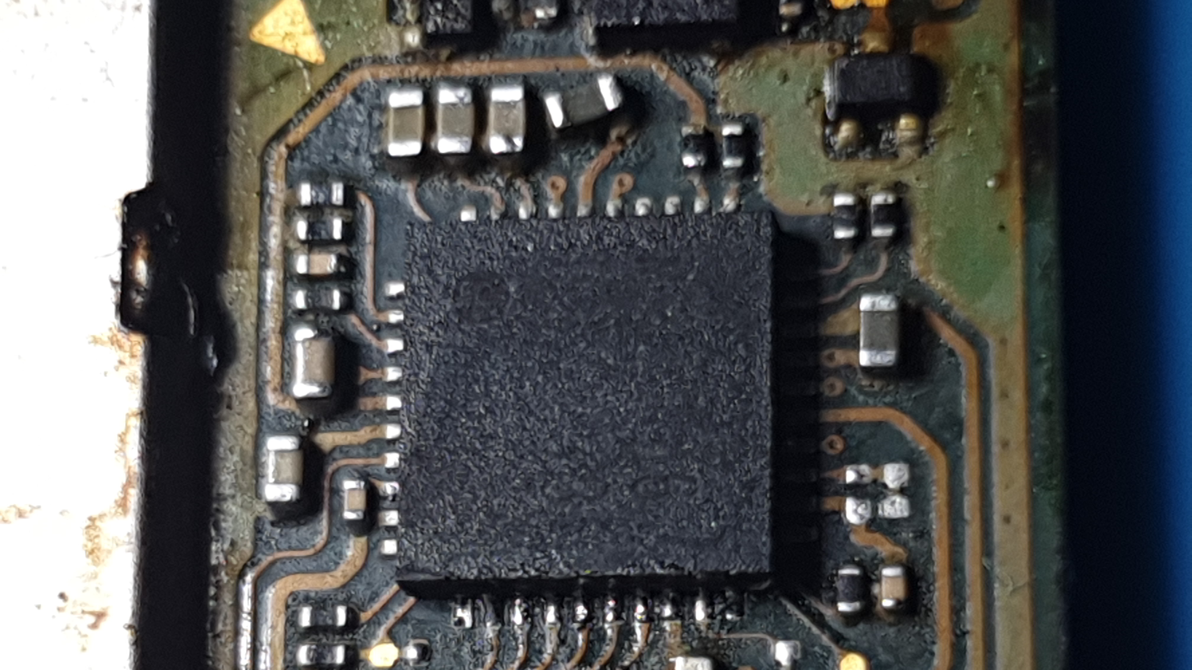
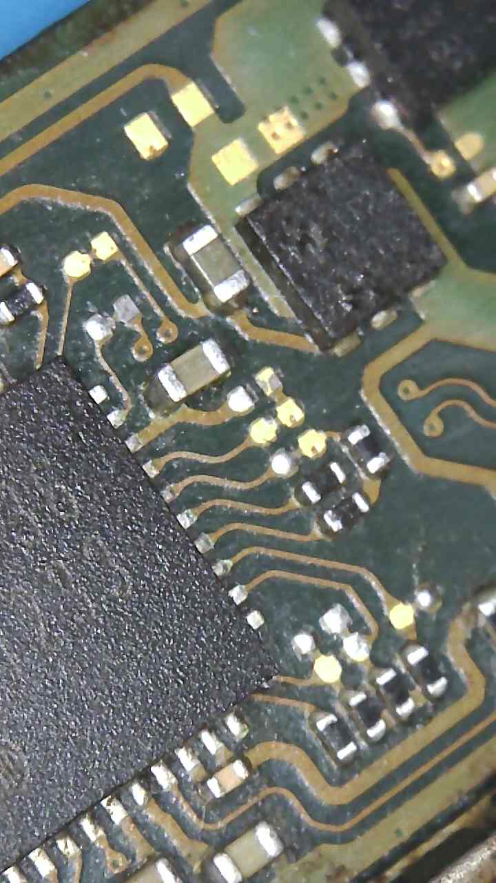
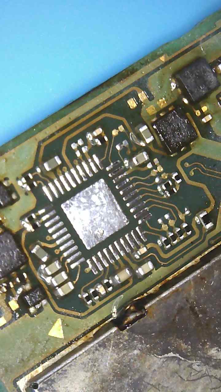
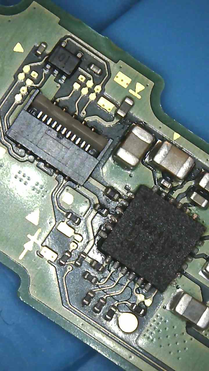
Here’s the chip on now I am confident it’s on 100% and I carefully checked every pin is soldered on.
I just wanted to clarify in dioade mode I don’t get OL on esd dioades but in ohms or resistance mode(?) I do.
I moved that wonky cap in place (finally!)
And I can’t see any bridges anywhere.
Well done ![]()
Strange, and in resistance, if you reverse probe polarity is it OL or high megs?
haha ![]()
What do you measure on your center battery connector pin now relative to ground?
15.7
I also get OL.
Btw is worth changing the usbc as well?
Weird. We’ll come back to this later if need be but for the time being leave it, given your resistance measurements, it won’t hurt anything.
Well, time to move over to the BQ IC I reckon, If you highlight where your diode readings don’t compare to Calvins charts.
Save it til last
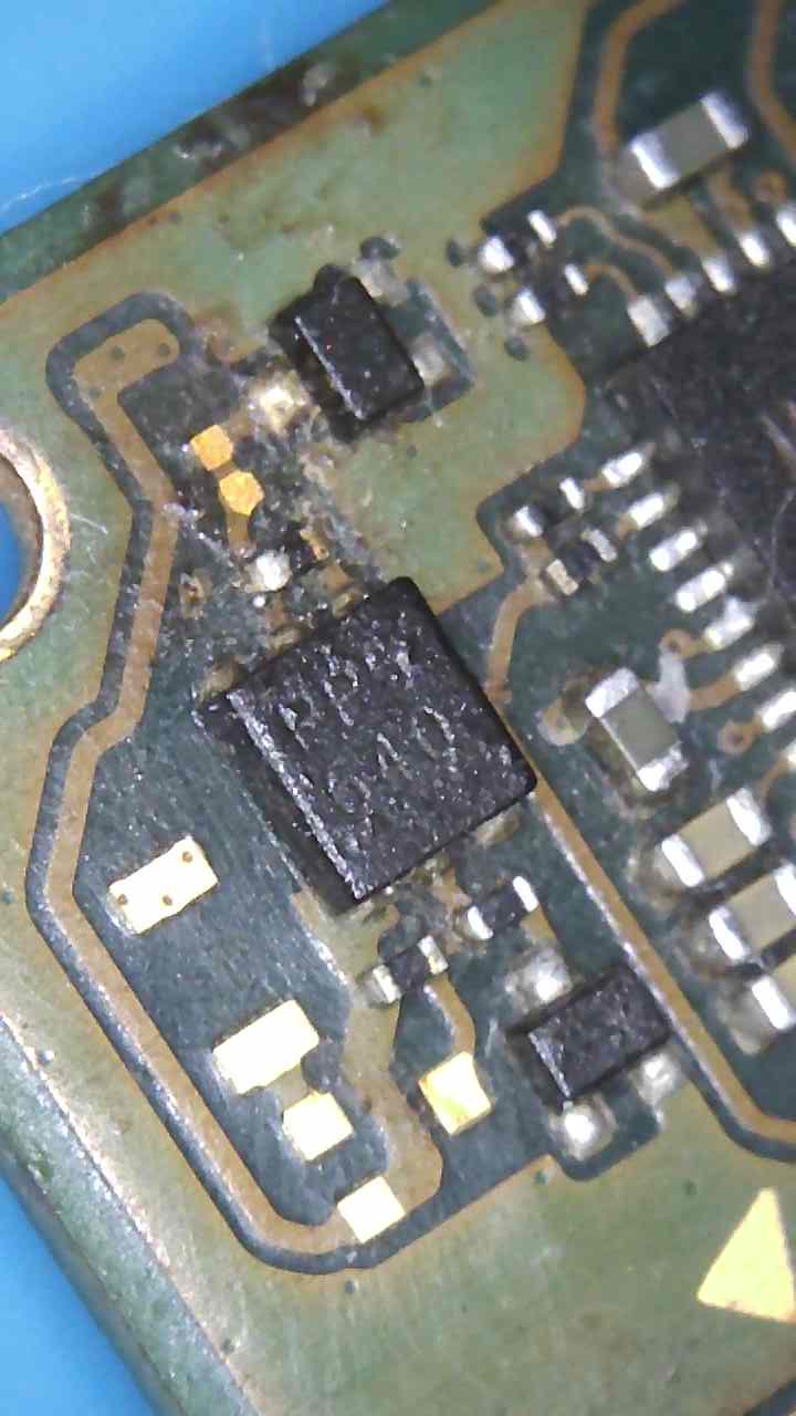
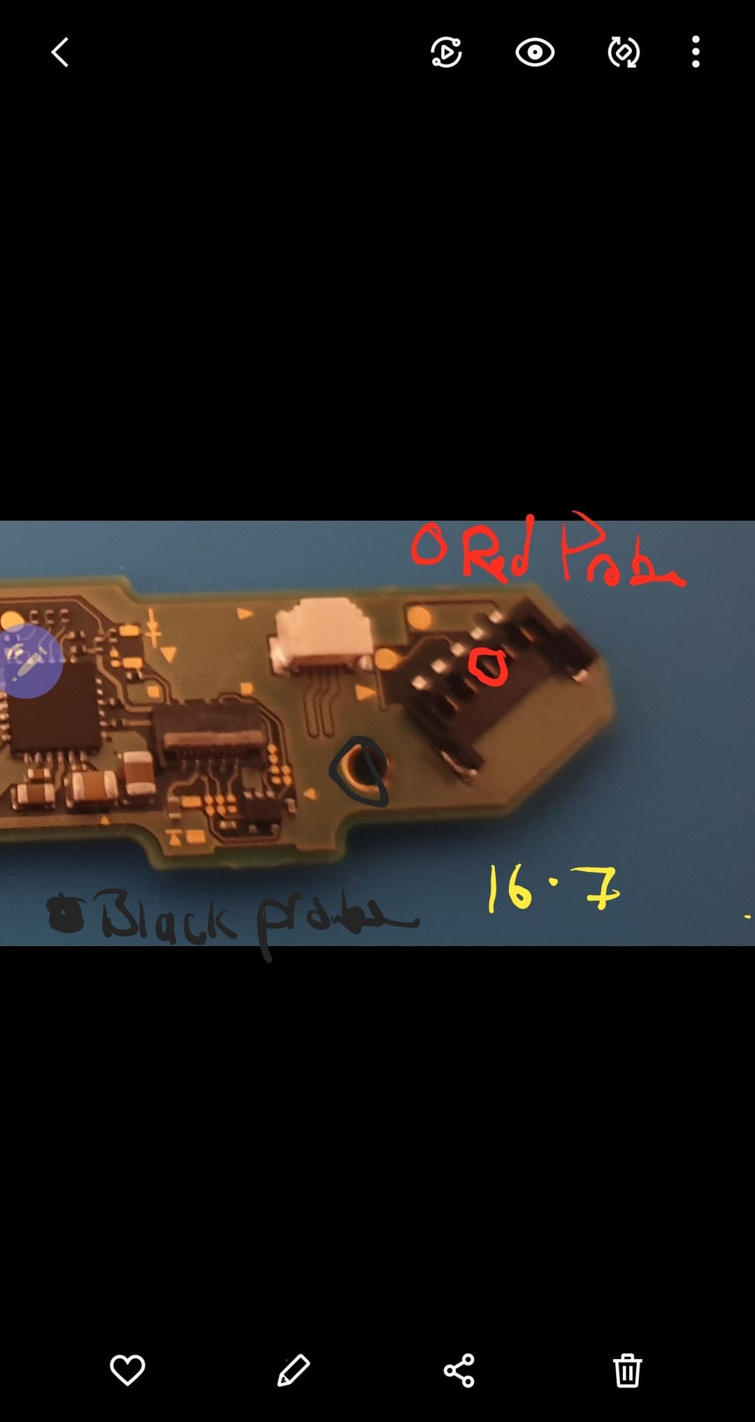
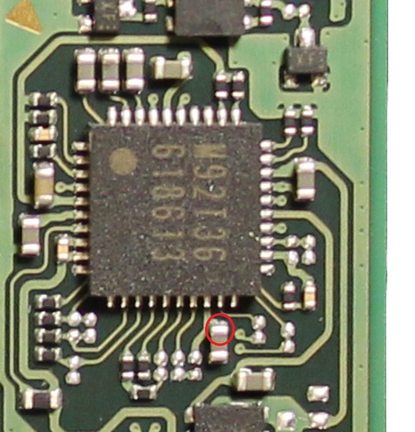
Everything seems spot on, only thing that came off as a concern I highlighted in picture, esp that resistor seems off by far.
the side of the 100k resistor you’ve highlighted in red is 1V8PDR.
Whats resistance to ground at your highlighted spot
The resistor appears to be a pullup for the joycon (connector) though i haven’t delved into it
Oh dear…
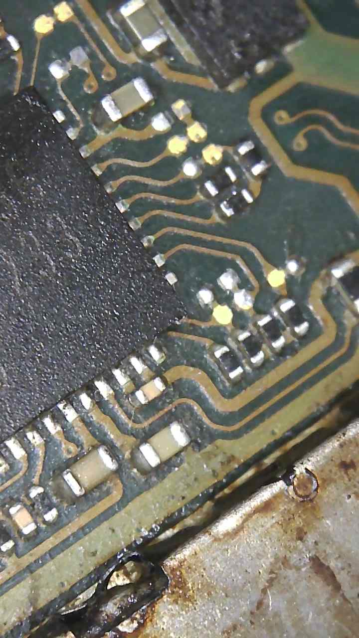
Can you take that reading here also just to confirm
And a reading relative to ground here too
This 56.05 . This cap did move and I did put on again. Wondering if it on fine or something else. Maybe solder splater.
The other reading is 1.08. Bad news?
Looking at your image it appear that cap needs a push up slightly.
Might not directly be the problem, provided there isn’t bridge accross it or to something else the cap itself is likely not responsible.
Yeah, that’s bad.
You can either pull BQ off to start with or…I’m sorry to say M9 IC again and see which (if any) resolves the short (which may be putting a secondary fault on 1V8PDR)
I suppose on the brightside… we’ve explained your funny readings on the diode and battery pin ![]()
btw you did check there was no shorts accross/between USB pins right?
![]() would it make sense to start on the BQ? Just got be careful of the plastic connector nearby.
would it make sense to start on the BQ? Just got be careful of the plastic connector nearby.
Well am glad am getting somewhere.
I didn’t register any shorts on the board. I had 2 on thrle M92 but they went after replacing.
How do you mean? In diode mode?
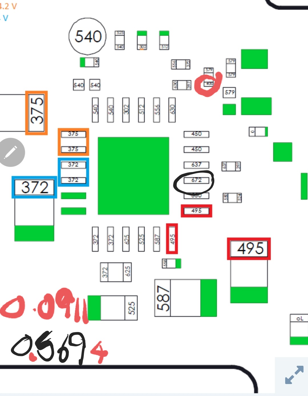
Your reading of 56.05Ω on 1V8PDR constitutes a short in this case (as it’s normally in the kiloohms relative to ground)
Your reading on one side of the Inductor relative to ground of 1.08Ω constitutes a dead short (on SYS)
In continuity mode.
I would probably start with removing M9 first because of all the rework and see if the shorts clear. If not pull the BQ IC.
If your worried about the connector, cover it in a shield, like what you’d find covering the SoC or WIFI, you can grab the from an old iphone too
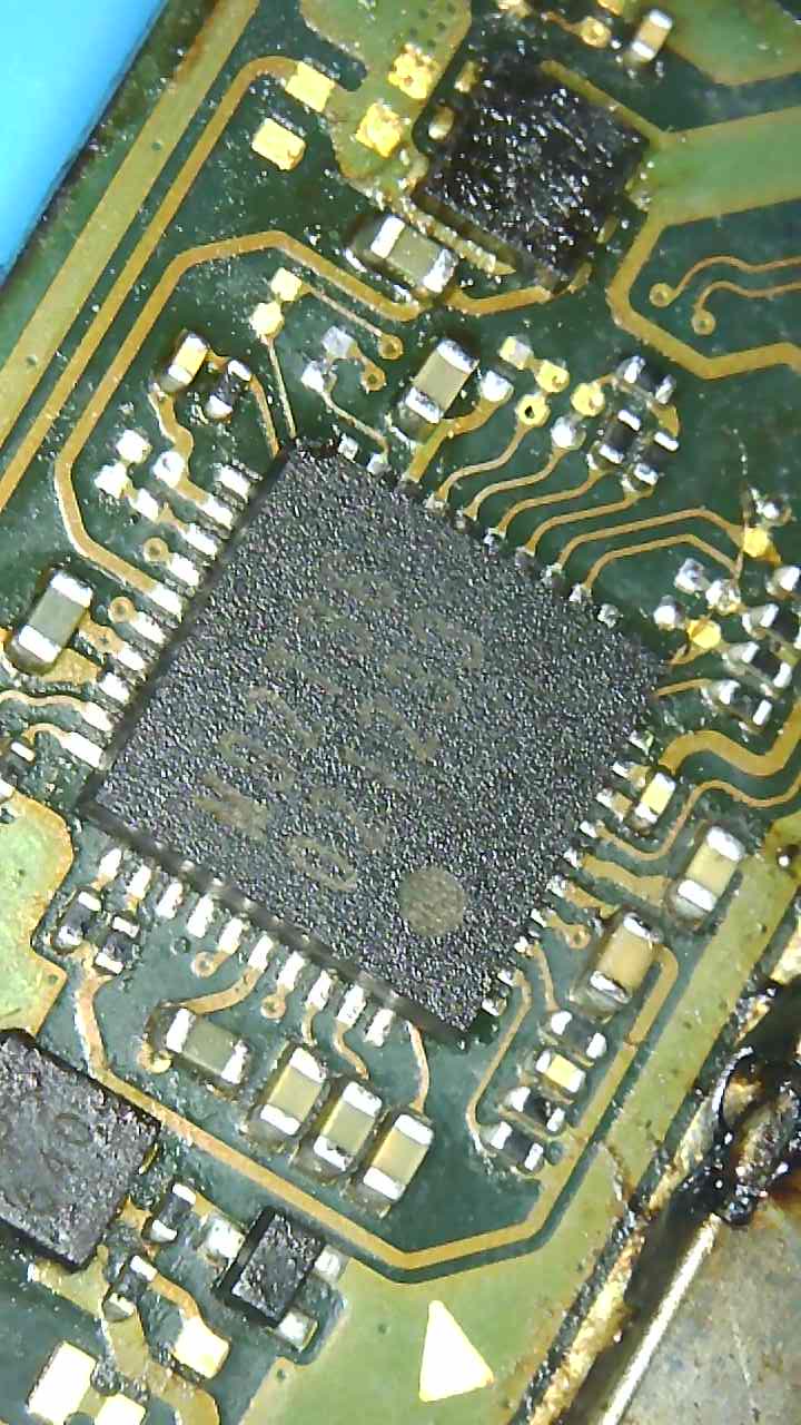
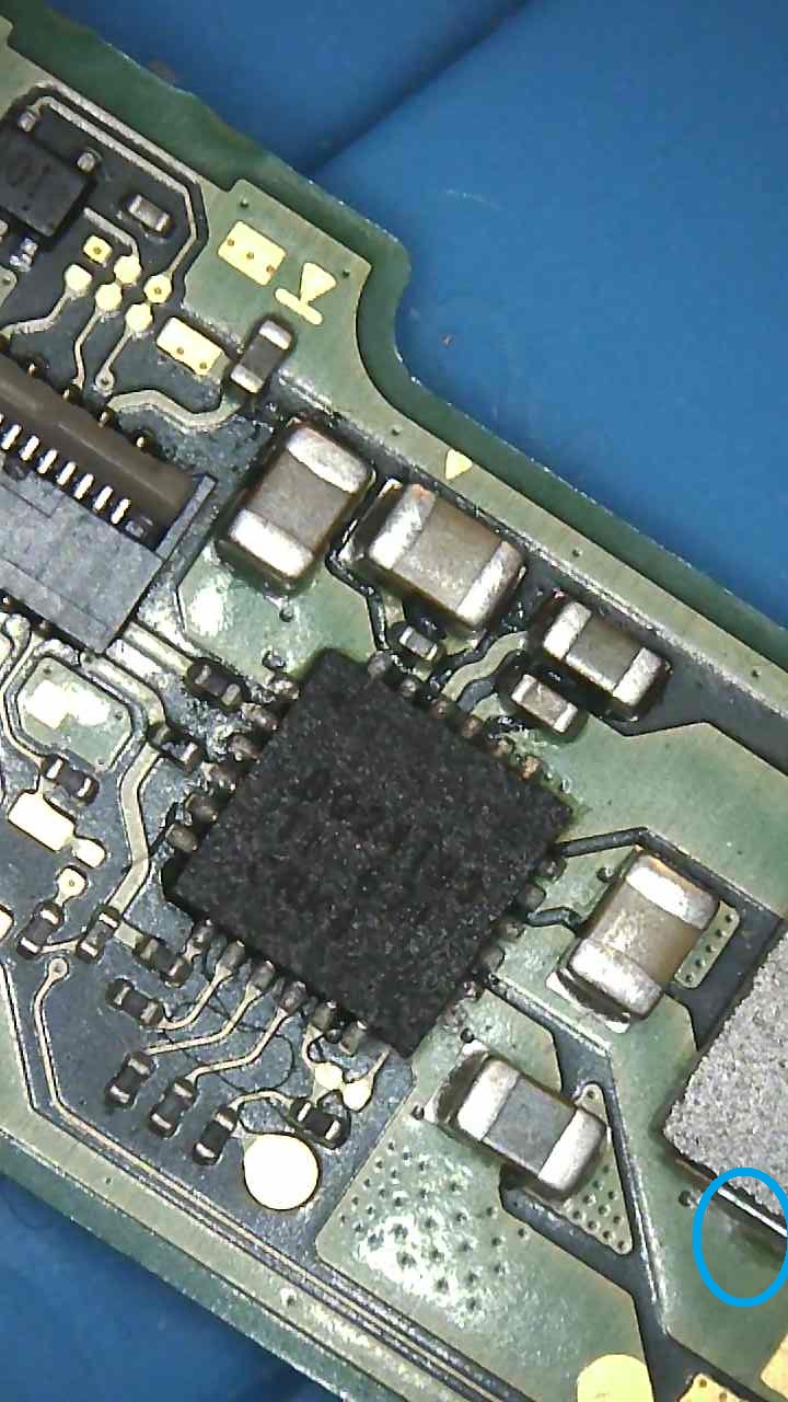
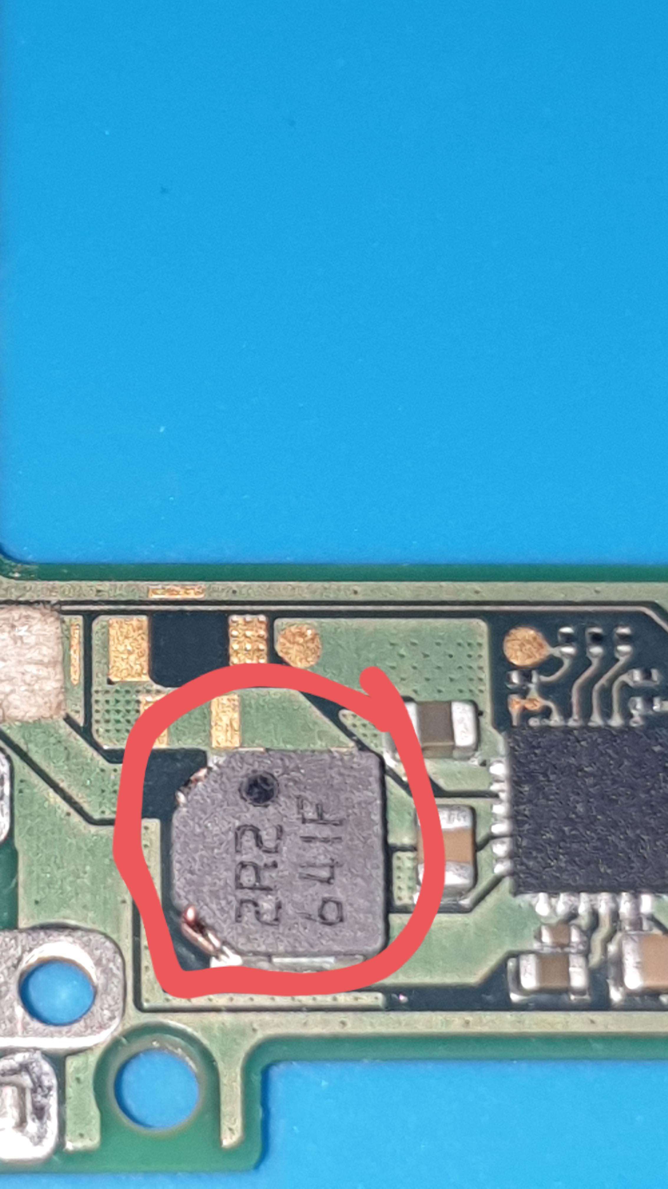
Should just add, you could pull that inductor near BQ (the blue highlight), then see which pad is short to ground, depending on which side is short, it’ll tell you whether it’s BQ side responsible or something downstream
Coincidentally, the same rail short as your lite and the same method & diagnostics
Just saw your other post haha.
Well I pulled the M92 and I tried to sort the cap out not sure if I made it worse but the reading 19.96 on the cap
And the other point is now 1.4709. What should they read?
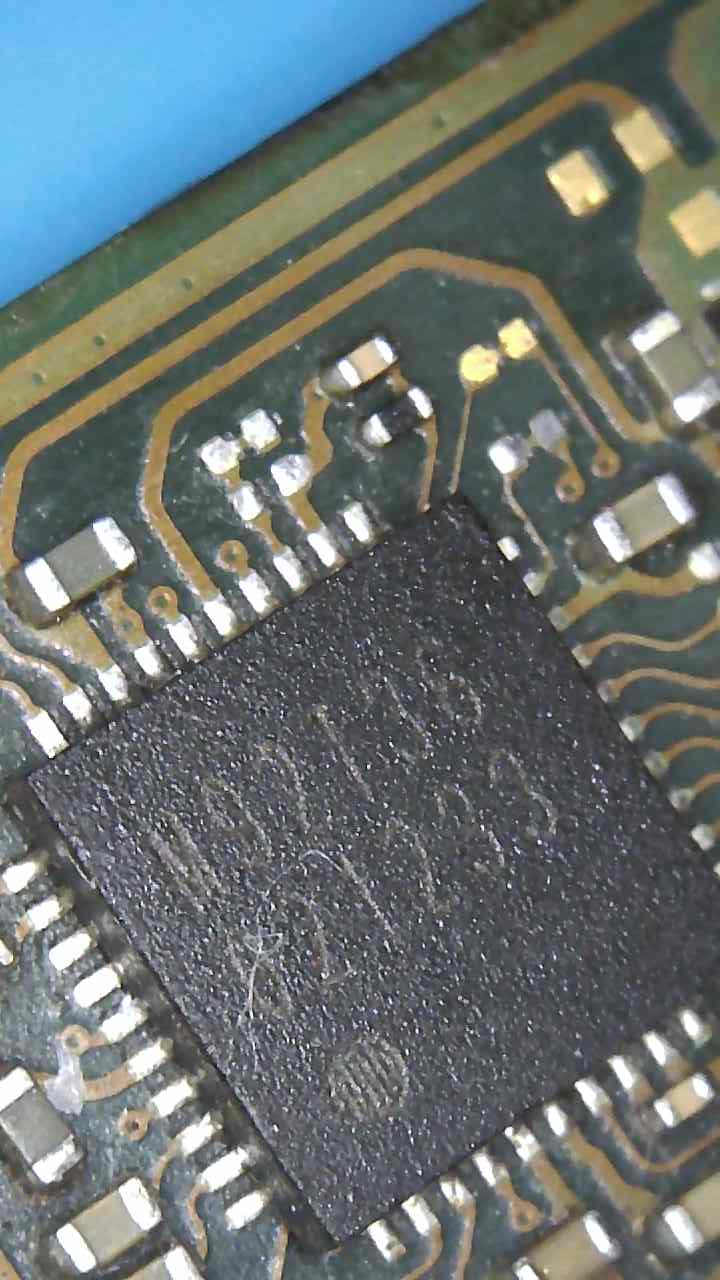
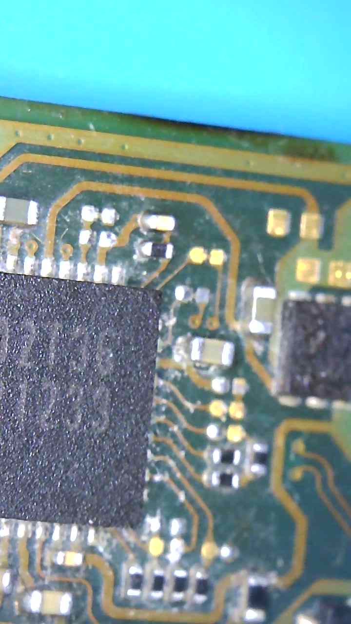
Is this the inductor
Just add I had continuity on usbc on pin 4 from the left and pin 4 on the right.