Strange, check you haven’t got any bridges across any of the M92 pads on the board. If your worried about that cap, you can just remov it for the time being.
Yeah. If the reading remains approx the same, then remove that inductor and see which side of the inductors pads remains short to ground.
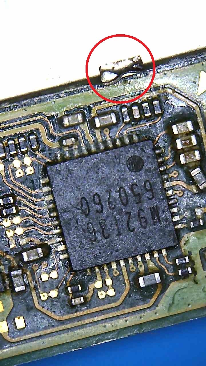
I thought it was because I pressed the range button but I wasn’t able to replicate that result again. So am not sure all I did differently today was a quick ipa clean on m92 pads
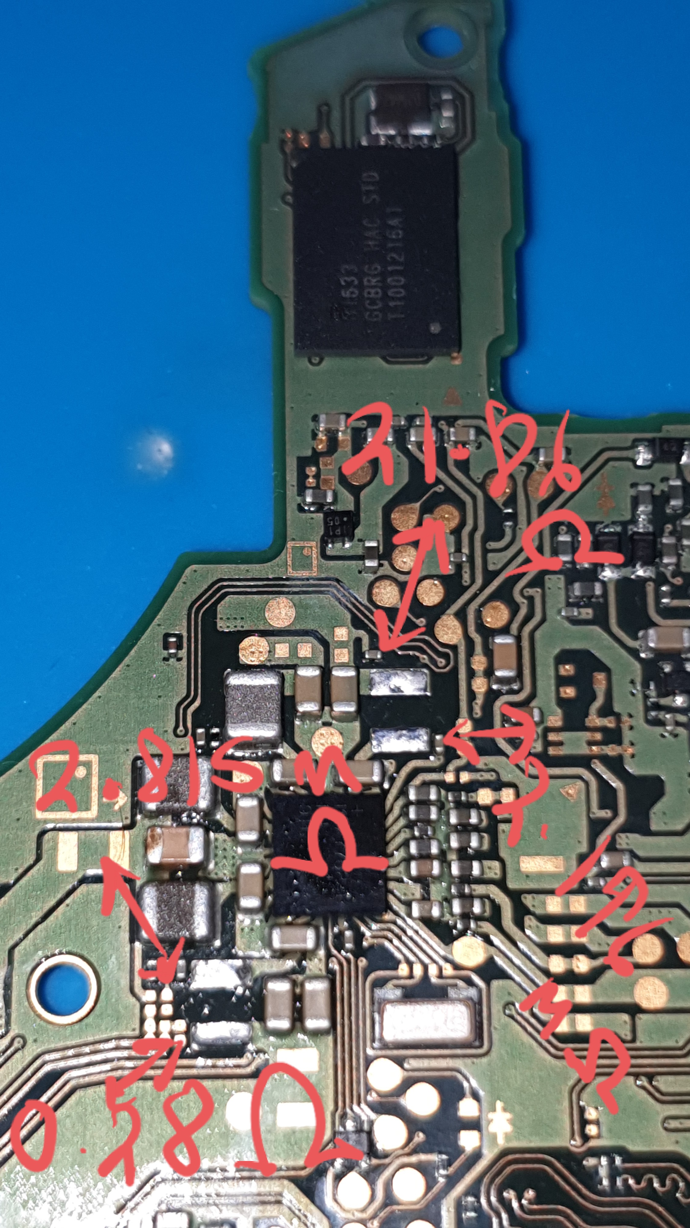
My guess would be Ram or SoC unfortunately as the two rails which are shorted (Red and Purple) feed them.
If it were me, I’d pull the Ram and see if the shorts clear.
You could also pull the incductors off first on the slim chance it’s the main PMIC responsible, though i think it’s unlikely and you’ll likely find the short/s is on the indctors output pad side…but you never know.
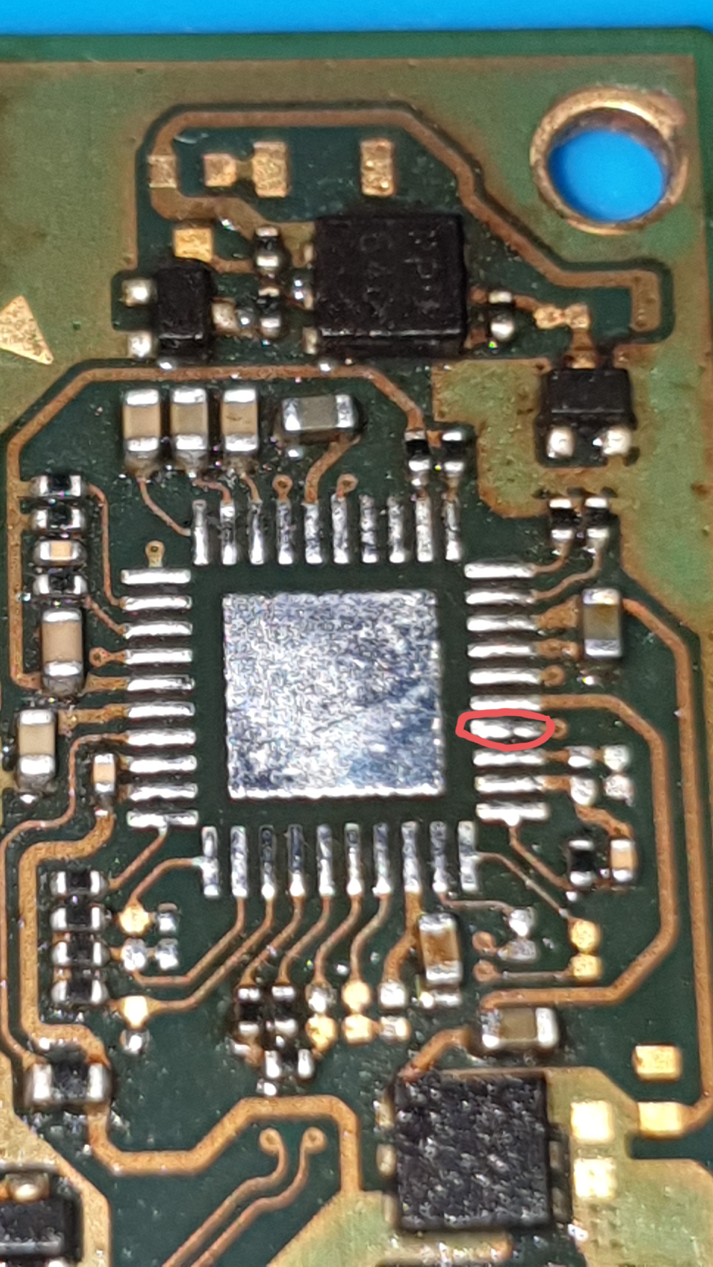
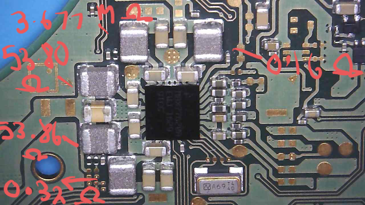
The two inductors surrounding main PMIC, representing the shorted rails. Red and purple, 0.16ohm and 0.32ohm, pull those two and see which side of the pad the short remains on
It’s a bit strange that your reading on red (1V8PDR) went from 0.16ohm to 21ohm did you change probe polarity or something?.. regardless, the short is on the output which lets us know it’s not the main PMIC responsible and it’s something downstream such as the SoC or Ram.
Nope no map unfortunately, I just stripped a donor board of all major IC’s and buzz it out in contunuity mode.
No just had black on ground and red testing. I might leave this one on hold until I decide what I should do with it. It’s shame though. But at least I’ve learnt loads thanks to you
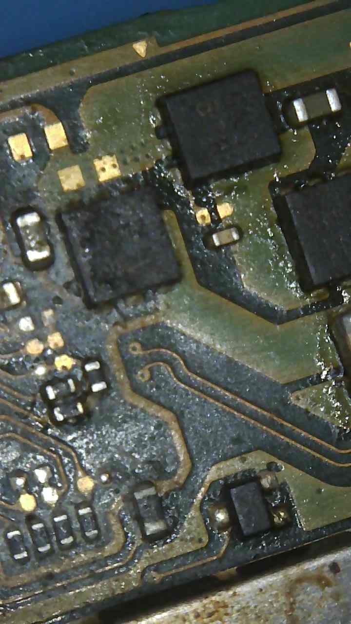
btw i forgot to ask, since removing the inductor next to BQ and the short to ground here spontaneously clearing, are you still measuring the short on the battery connectors center pin?
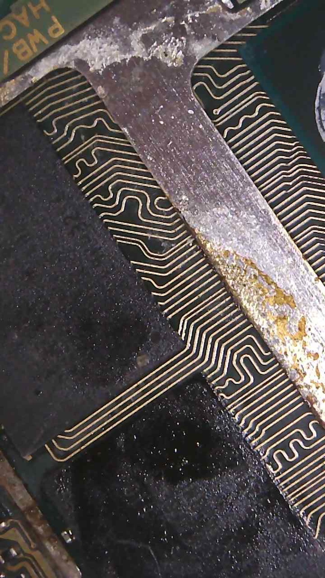
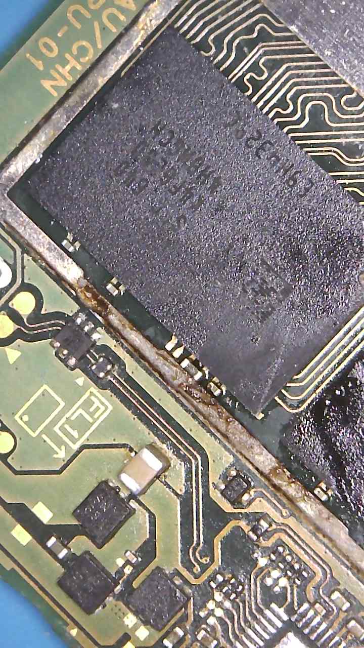
also, i don’t know if we established this earlier or not, but looking at your earlier images
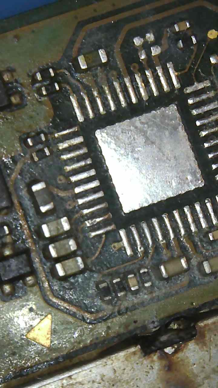
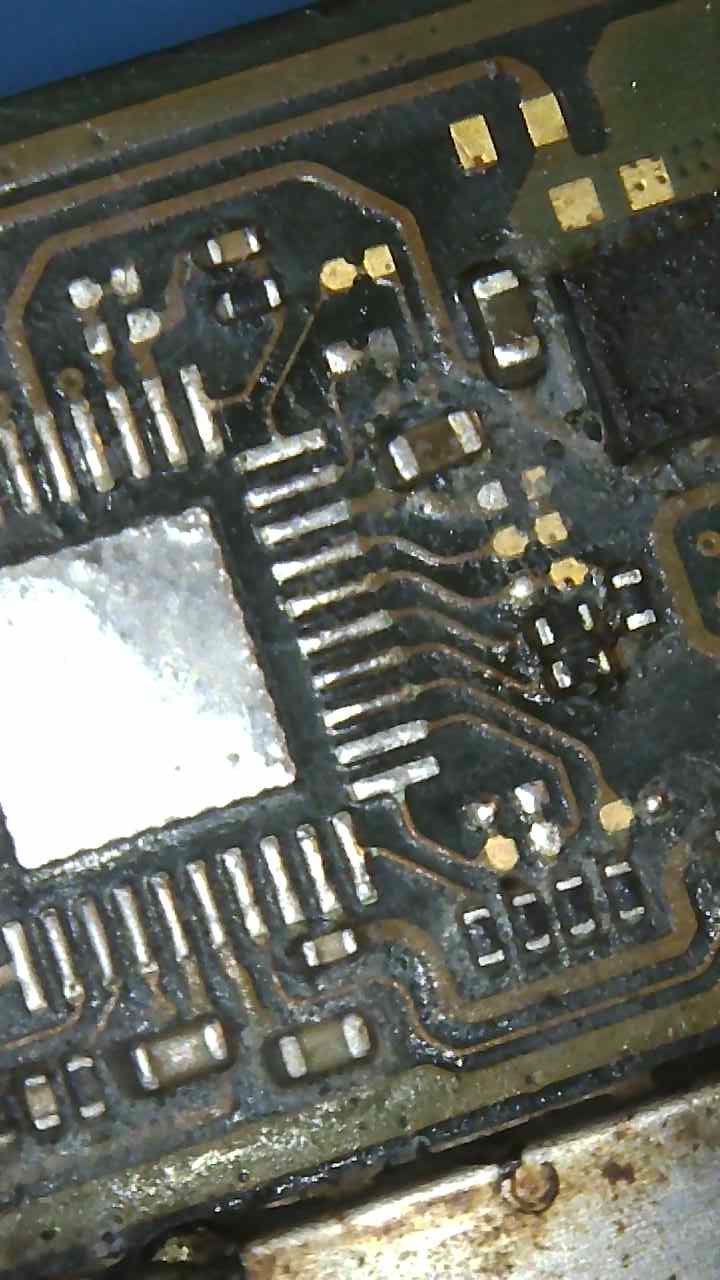
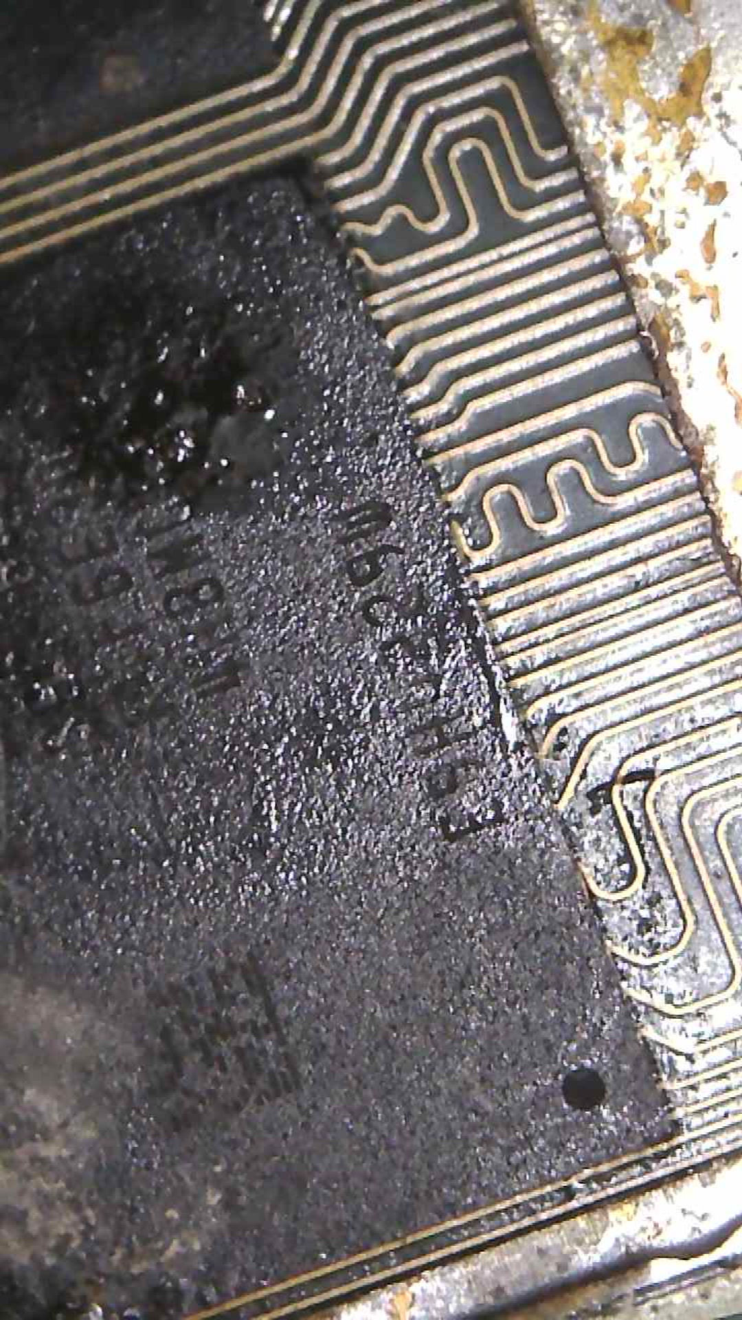
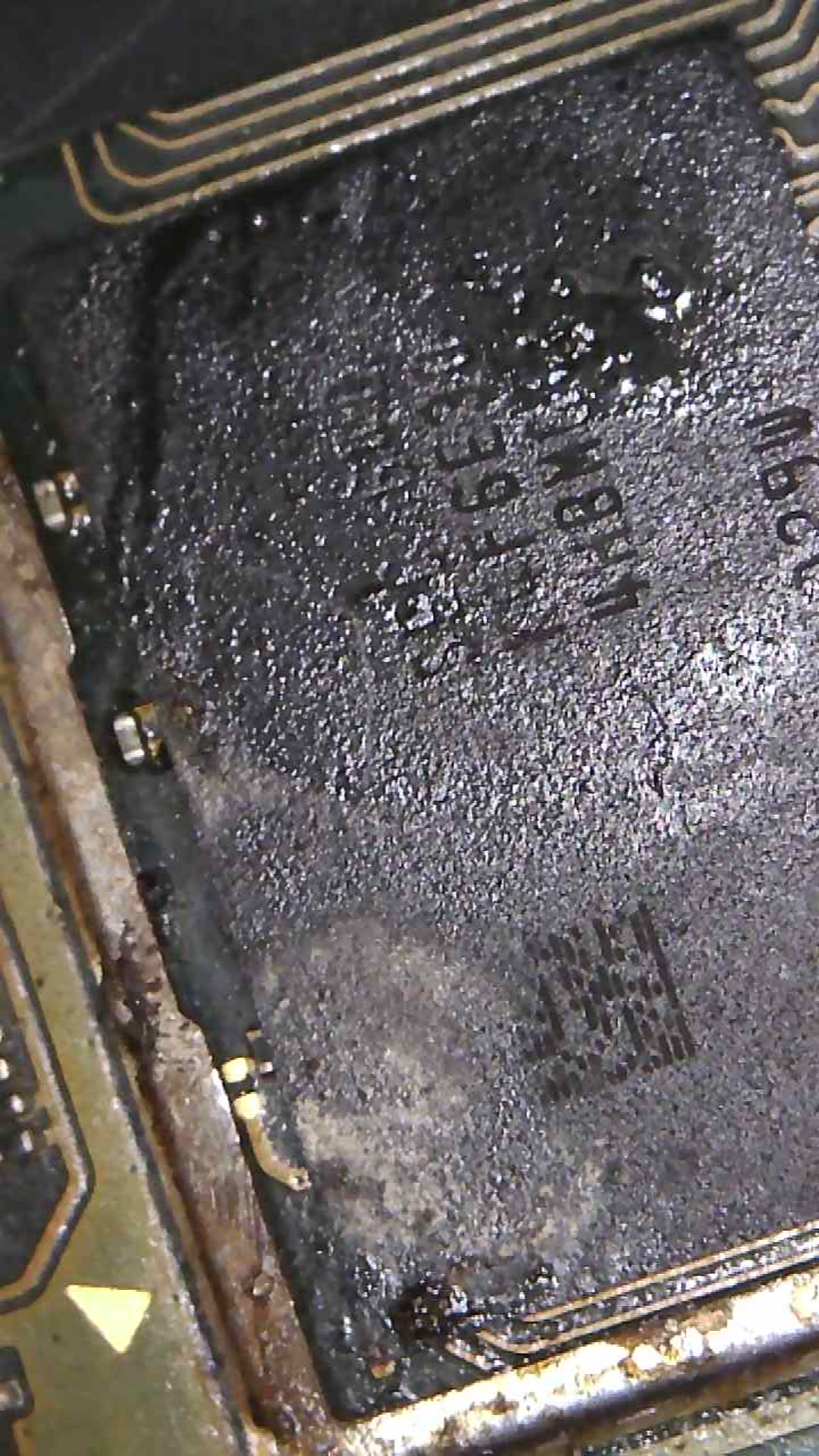
It would seem somebody has already been under this shield and possibly already attempted to reflow Ram or SoC… it might be worthwhile removing this shield and taking a look like in your other case with the Lite board and seeing if there is any evidence of a reflow…, it’s entirely possible if somebody attempted a Ram reflow and accidently knocked one or both of these modules causing the short your seeing on these rails, in which case that would be potentially good news
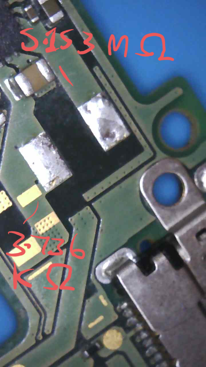
Yes I am getting 15.65 M Ohms on center pin to ground.
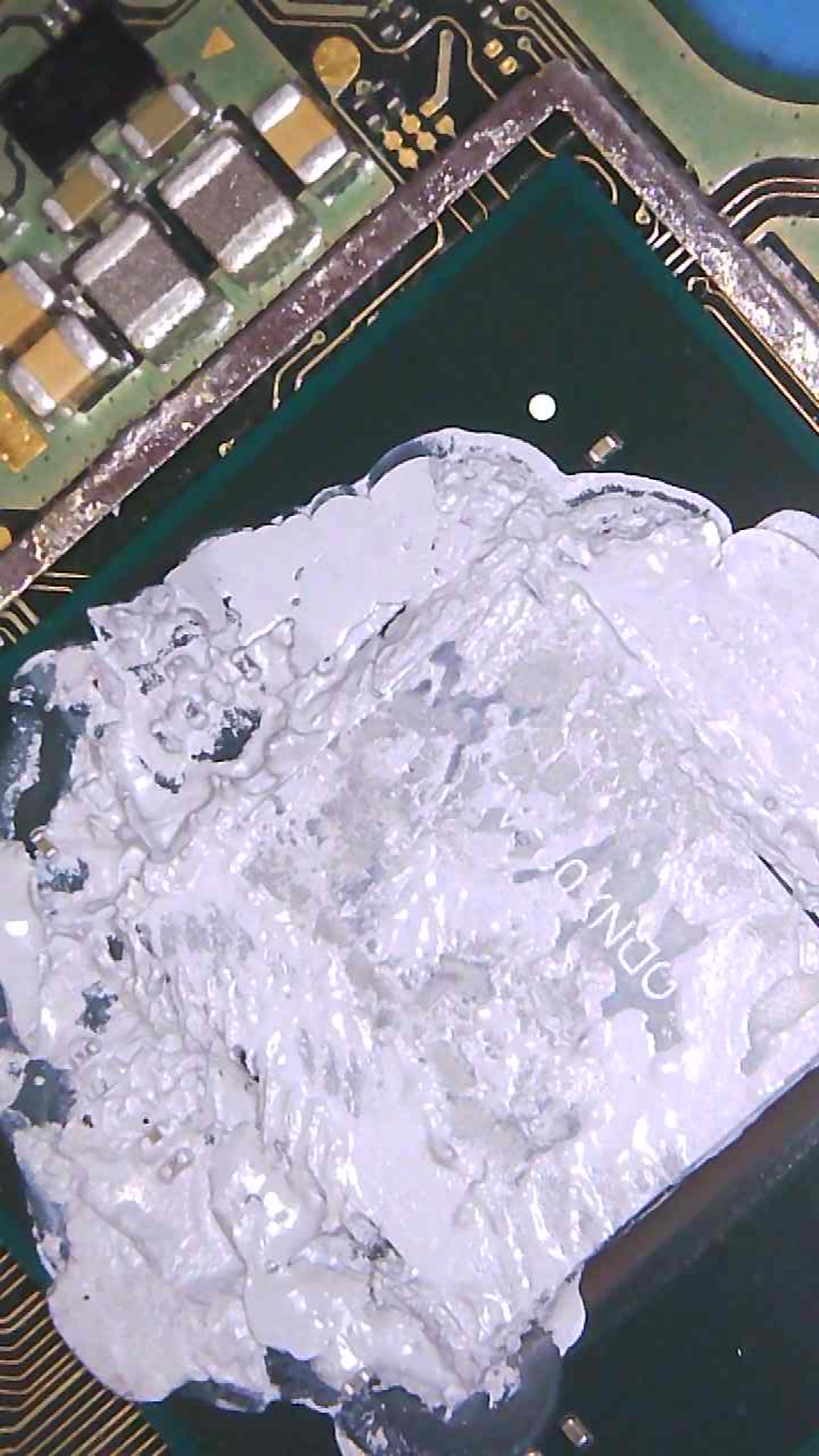
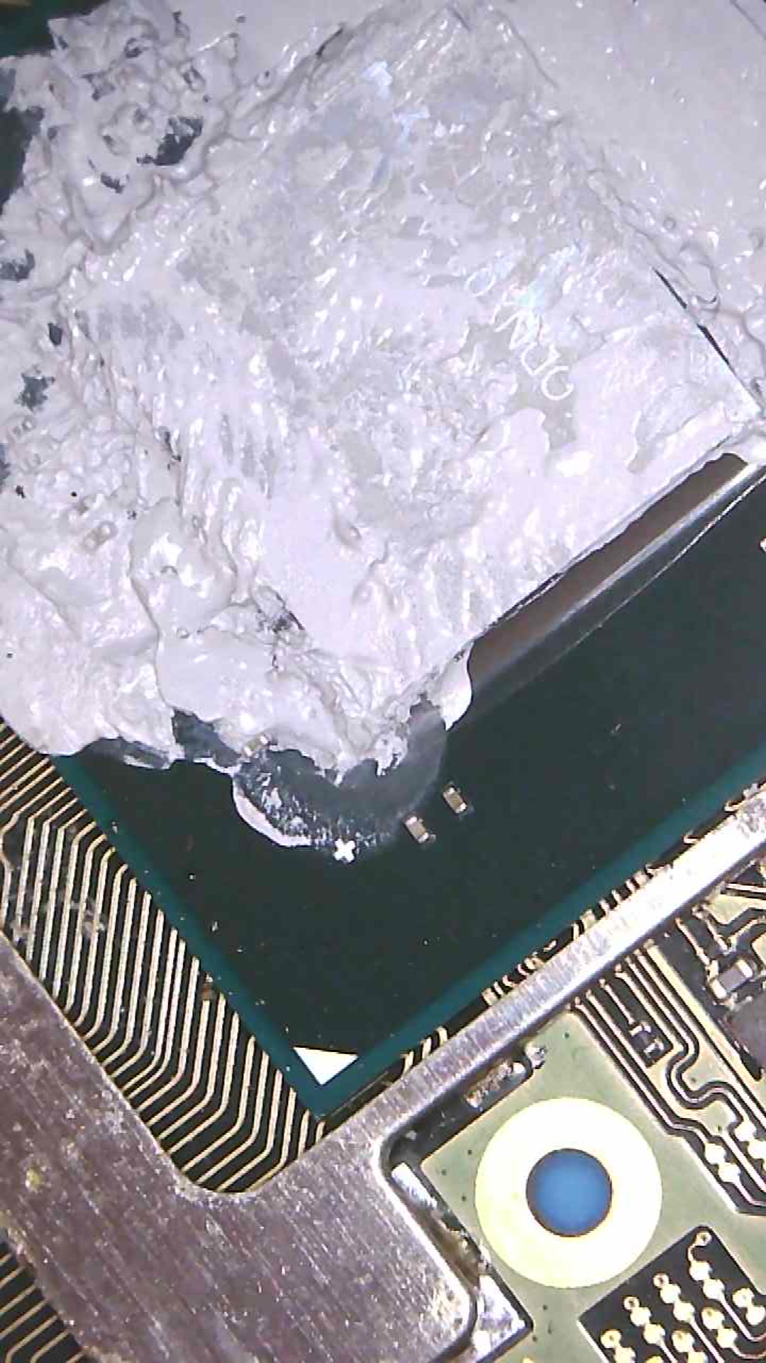
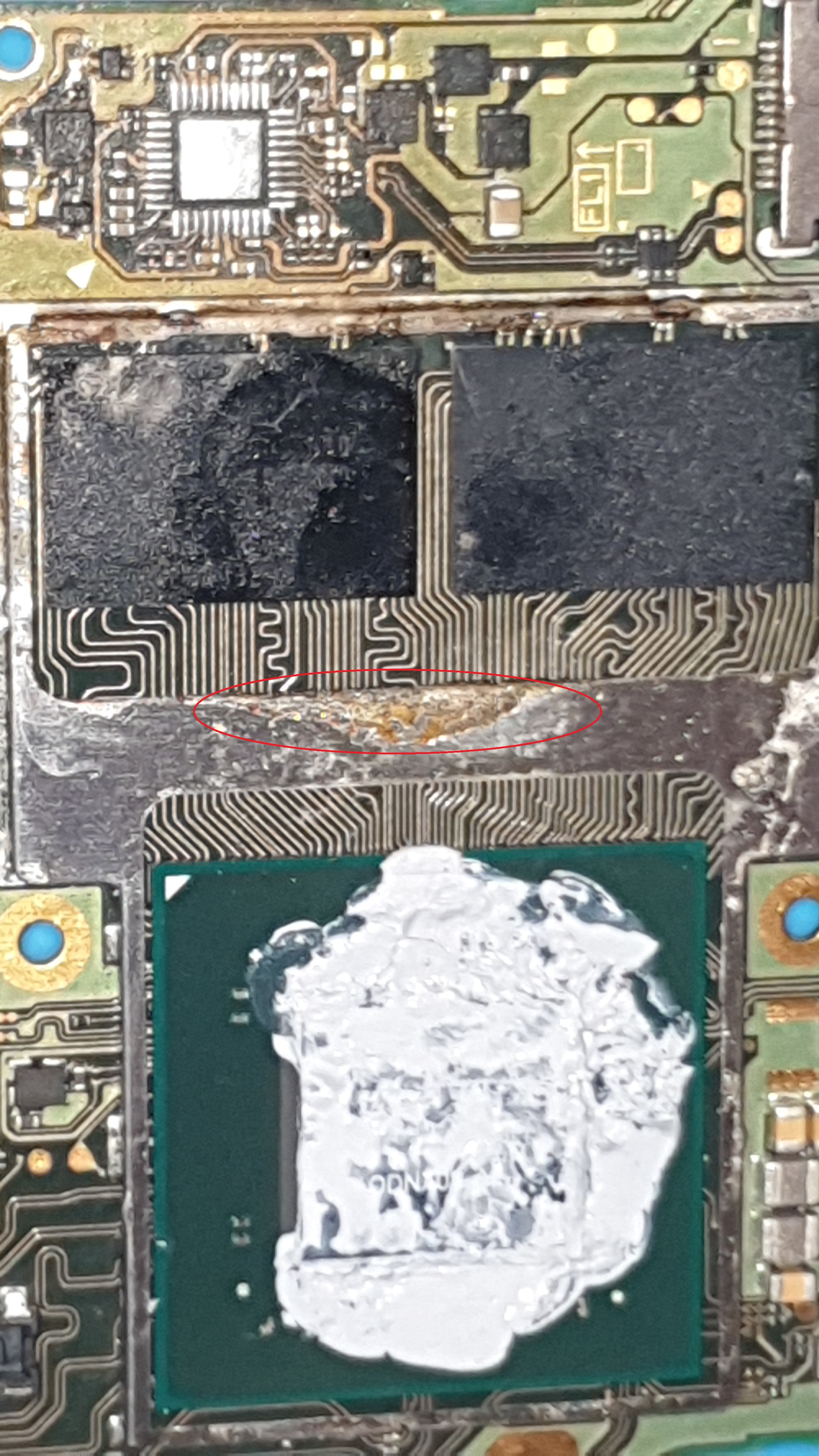
Also I am pretty sure someone has tampered the soc/ram shield. I’ve taken some pictures. Looks bad but maybe I contributed to it by heating aroubd m92 a lot. I havent touched this part of the board. Tbh looks like (ram) is where it should be?
I will also get back to you about the lite soon. But i am assume same treatment with IPA for this switch as well?
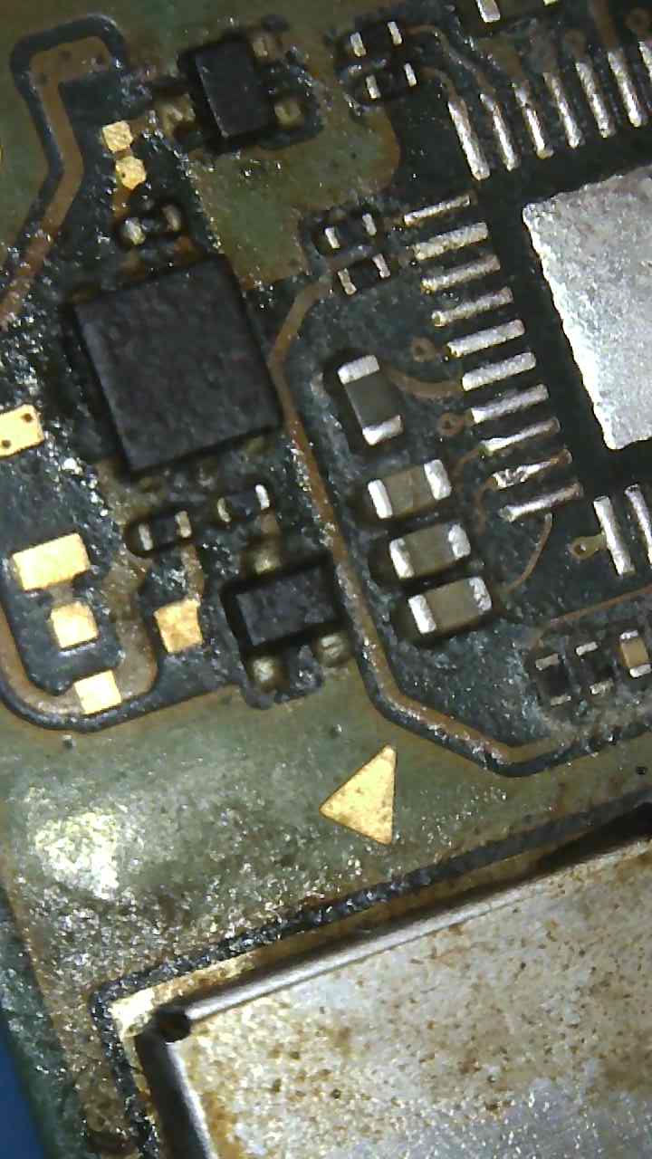
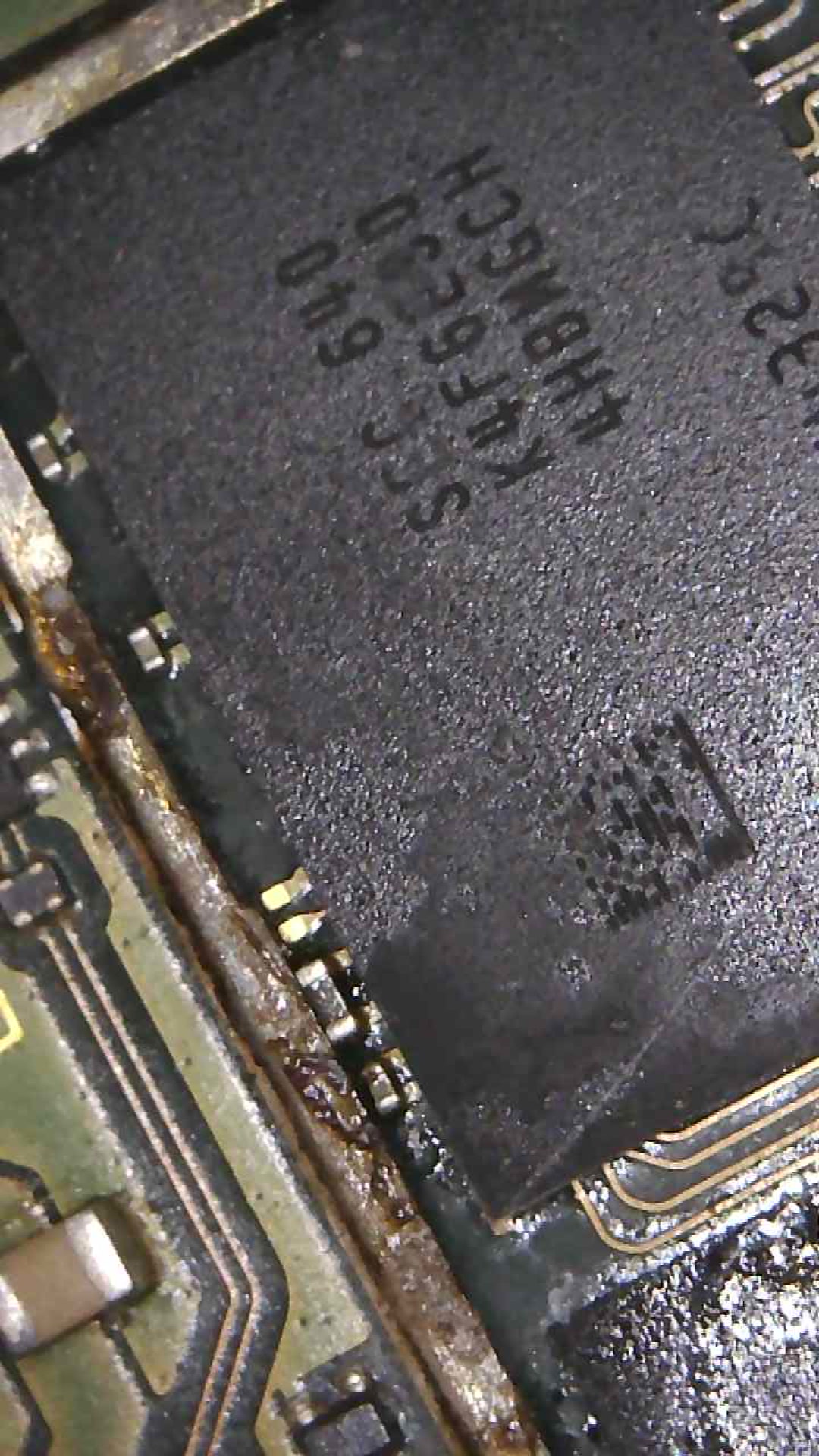
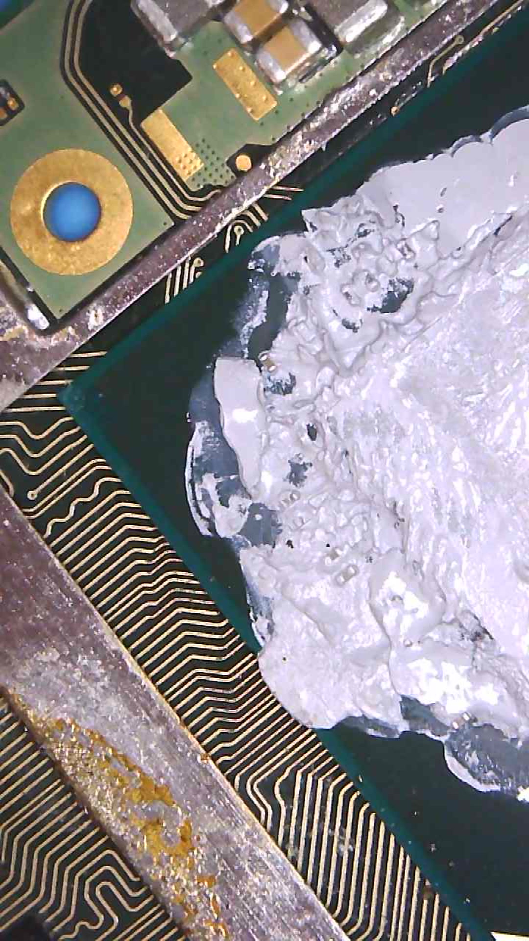
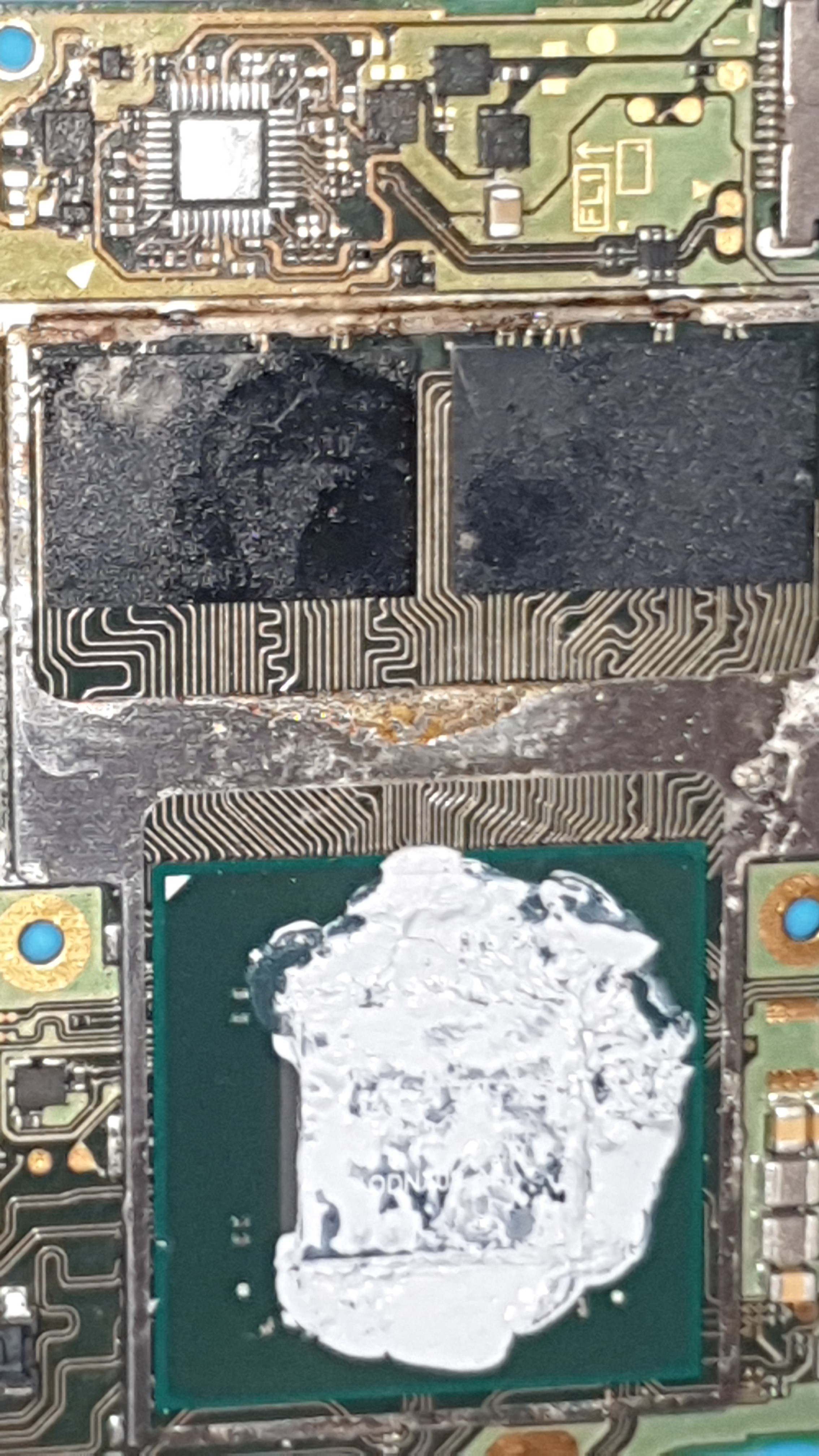
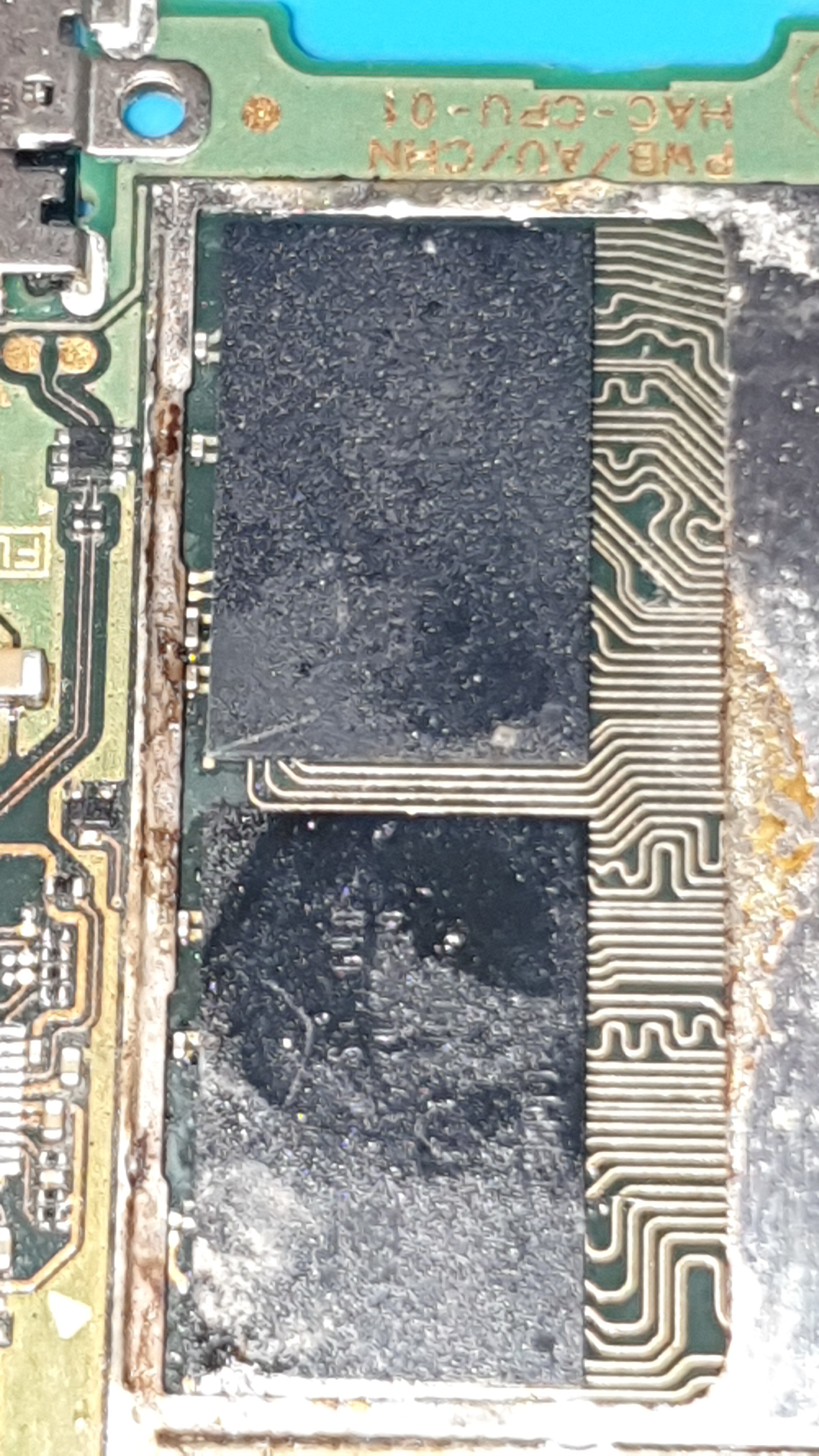
Flux residue here would indicate somebody has reflowed Ram (either intentionally or accidentally) I would be surprised if your flux made it that far in, but not impossible i suppose.
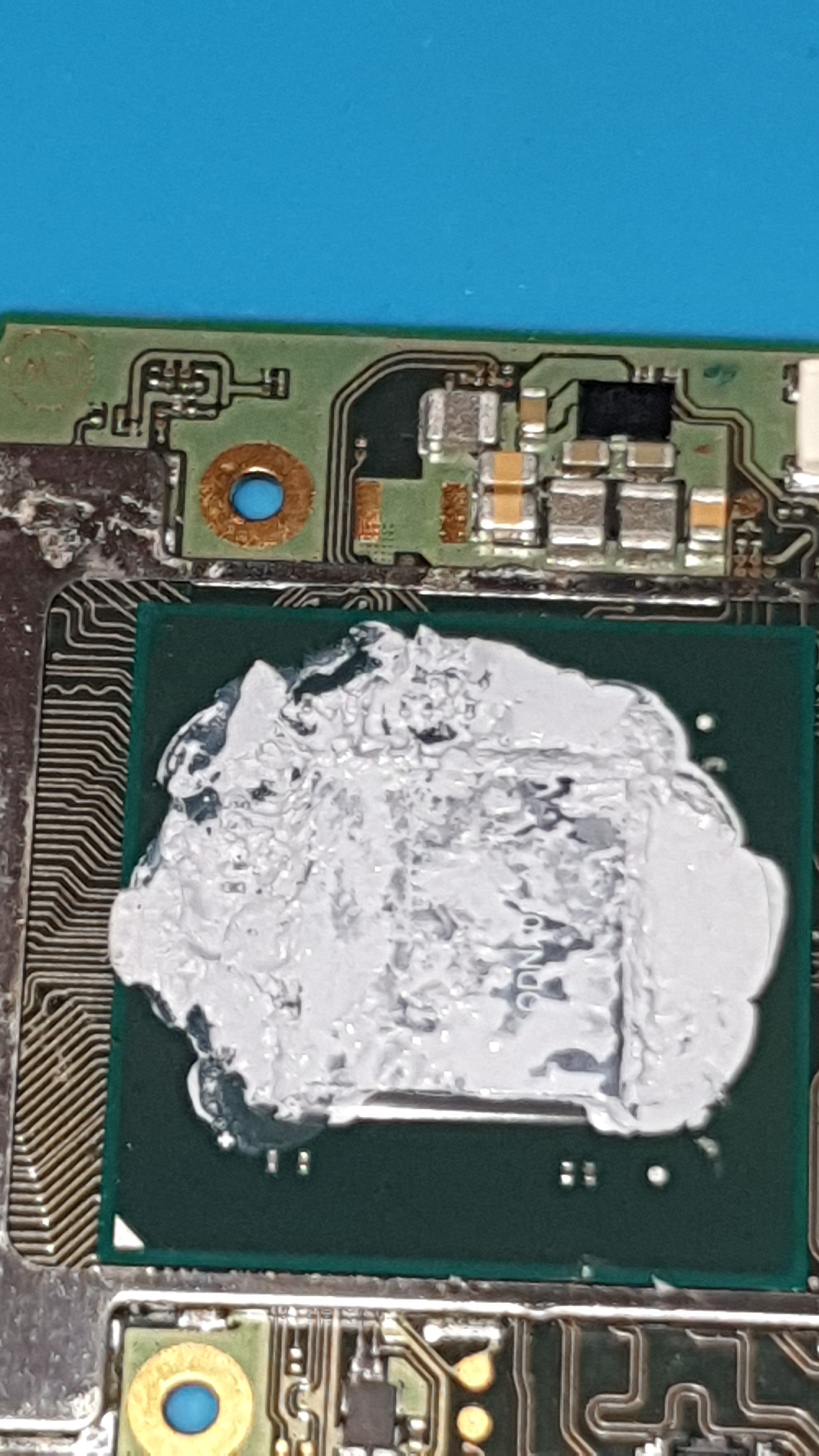
The SoC on the other hand looks near immaculate and doesn’t appear to have been exposed to excess heat, which is a good sign.
It is indeed, but what i mean is, the ram may have been knocked or over nudged while solder was molten merging the balls below and surface tension will pull it back in place… just a possiblity. You could tilt the board and inspect the outer balls for any issues such as bridges etc… though it’s pretty rare your ever lucky enough for a bridge to be on the outer most row where you can easily see it
Yeah you can do, just skip the heat step as this regular board doesn’t appear to have suffered liquid damage so it’s not needed here.