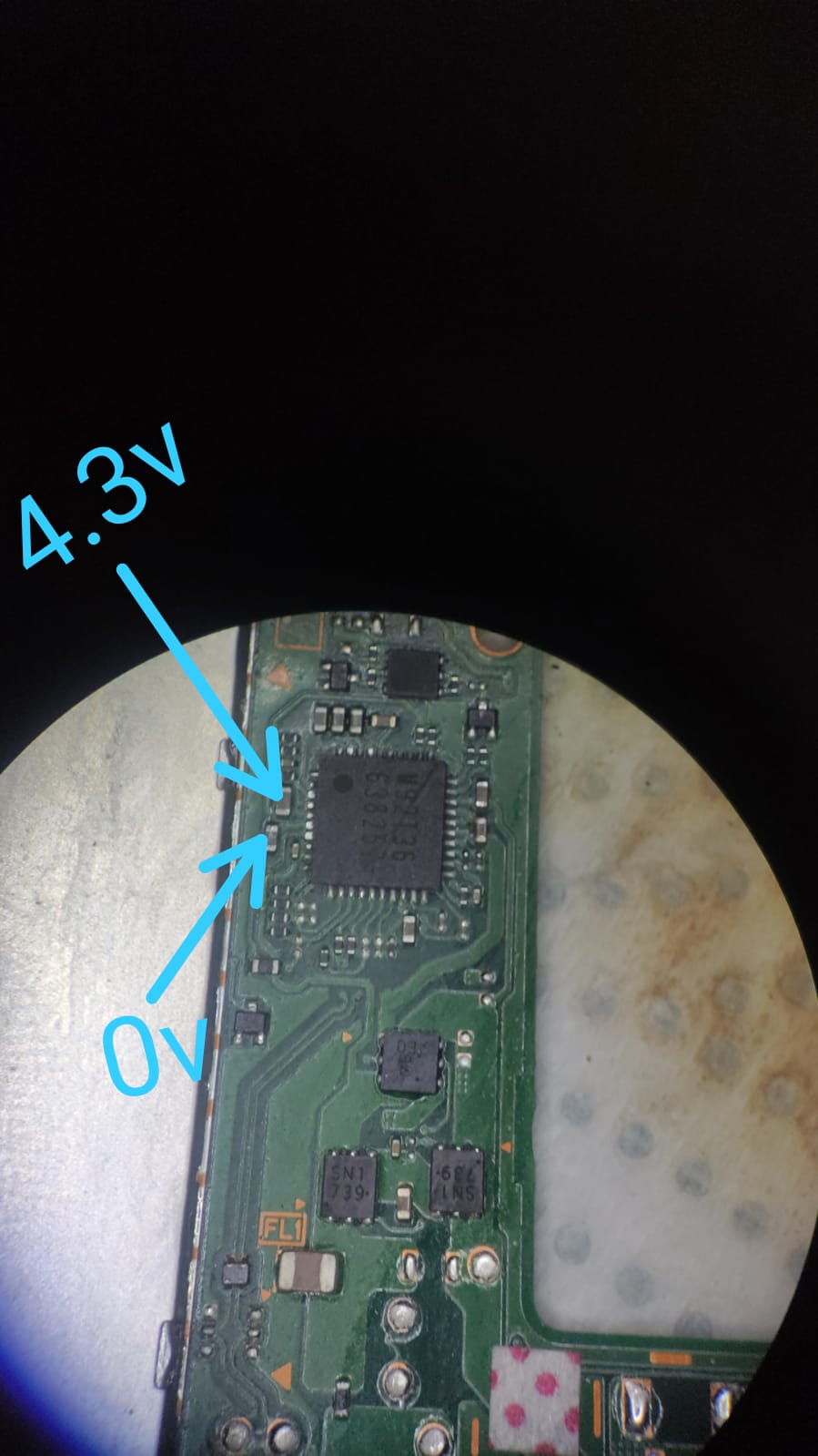
Hello friends, could someone help me? I have Switch on the bench that hangs on the second logo of nintendo, when analyzing it I found that capacitors next to the M92 are with incorrect values (4.3v and 0.0v), I changed for an M92 of a scrap that is functional, however, it did not solve, any tips ?
Check if the to resistors or whatever its called next to the left of the soc has a reading in diode mode (had a board where someone try to pry the shield open and damage one of that tracepad n cause to stuck at 2nd logo)
The other is reflow or replace wifi ic has also fix another board thats stuck at 2nd logo
Third one is a software issue where i had to rebuild a new firmware and delete all the user info
Its was an unpatch switch, using biskeydump, lockpickrcm for prod.keys and emmchaccgen to build firmware with prod.keys file then write to switch with hackdiskmount n memloader
Due to bad translation, I believe that there is confusion about my case, I will try to summarize:
The nintendo when connecting hangs in the second logo, when analyzing the card I noticed that the PIN 5 and PIN 6 of the M92 are changed. PIN 5 0.3V PIN 6 5.2V.
I checked the values of the components with the red tip on the ground and the black one on the components, all the values that I have as references were the same.
I would be inclined to remove the M92 IC ensure there is no bridges across pads and with this IC removed take that measurment again if it’s truly 867 ohms
If the resistance remains the same, I’ll point you to another thread for clarification on your other rails, as it’s likely you would have a more serious fault elsewhere causing this
Ok no worries, so your reading of 149K is approx normal.
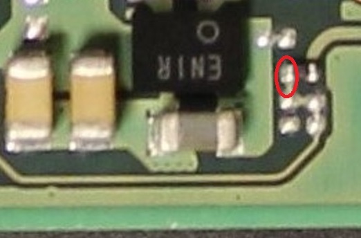
Next would be to check the ENXX IC is being told to turn on by checking the voltage at a few points, bear with me and I’ll find an image for the locations
K, so with the battery connected and the USB cable plugged in, black probe on ground and red probe at the highlighted point, what voltage do you measure here?
Make sure your on the voltage mode on your meter and not diode or resistance