Hi everyone! I am currently working on a switch that does not boot and doesn’t charge (0 amp).
I changed (brand new) M92T36, P13USB, BQ24193 and even the usb c port and still no success. I tried with a known good battery, nothing. Fuse is ok. Tried reballing the wifi chip, same result. Didn’t find any short checking random caps.
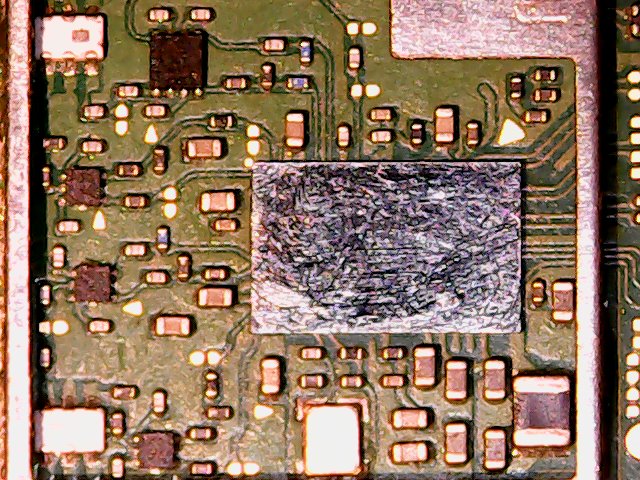
Sometimes, for unknown reasons, when I flip the board (the side with p13) and I check the voltages ( the yellow ones right above the socket caps
https:// www.tronicsfixforum .com/uploads/db3735/original/1X/5989c40dbe4a8918006418a20a5a25c9fc7071f9.jpeg ) with battery and 5v charger, it suddenly starts charging for around 1 minute at 0.47/0.56 amps, and voltages corresponds like in the photo(1.8, 3.3, 4, 5 v). After that time it stops charging and voltages doesn’t corresponds anymore ( I don’t have the 1.8 line anymore, nor the 3.3 or the 5 v).
Do you have any suggestions? Thanks a lot
Any chips or damage to the battery fuel gauge IC on board underside of battery connector? Have you checked continuity through battery connector to test points? Water damage has a habit of rotting the weak solder joints here…
Thank you for the response! Luckily I don’t see any kind damage in all the board. I checked with continuity the caps around the battery fuel gauge IC and are all normals,except for the one just above it (isn’t shorted to ground but measuring it in resistor mode shows around 86 kohms), is that normal? Then I checked the test points of the battery in both side of the board and everything is fine.
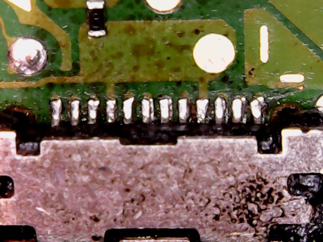
Sounds like a bad USB port, disconnect battery and check continuity with a USBC breakout to all corresponding points.
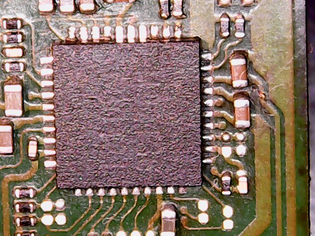
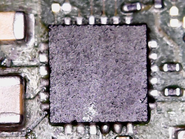
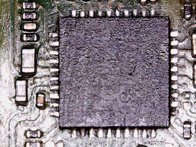
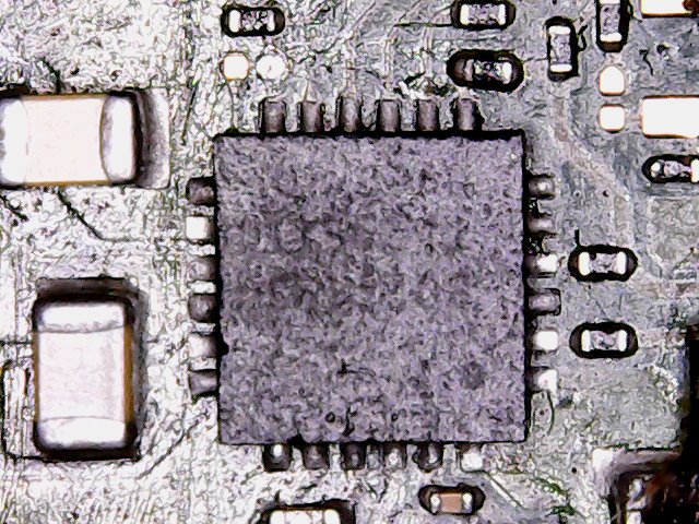
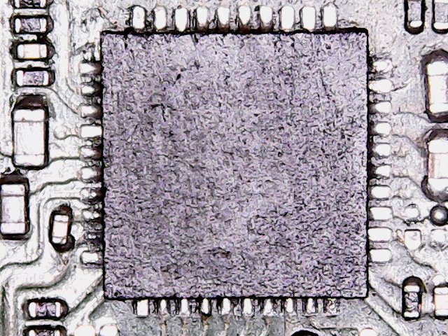
If you could provide photos of your board of the IC’s you reworked/replaced might also shed some light too
Sadly I don’t have a usbc breakout board, I made the photos (sorry for the quality), double checked usb c connections: no loose pin.
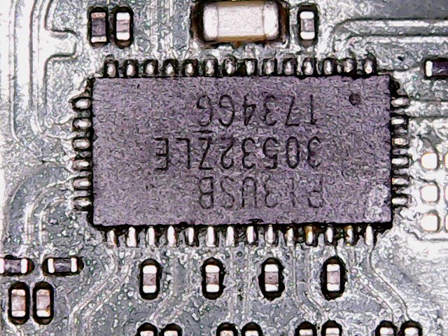
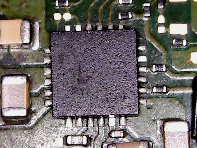
Looks like you have a few pads on BQ lacking solder, re-tin them with an iron, flux it up and reflow. M9 IC may have a few also.
After, plug in and see if there’s current draw, if not reverse USBC orientation
Tried refluxing m92 and bq with a little bit of more solder, still no current draw(with or without battery plugged in) in both usbc orentations.
You still seem to be lacking solder on some pads afaict. Remove IC’s and tin the outer pads on the on the IC itself, leaving the center pad as is.
Also inspect your WIFI IC at various angles and ensure no bridges.
Resistance to ground on 1V8PDR and 3V3PDR?
Thank you for the tip. I tried to tin directly the ic… but I don’t know if that is enought. What do you think?
Checked near the wifi chip, seems all ok to me
Sadly searched online and didn’t find where the 1V8PDR and 3V3PDR are located (near the max77??? I’m a little noob, I know). Would you mind tell me where to find them?
Also tried again with both usbc side. Just for 10 seconds I got around 0,26 a drawned, with battery plugged. Then still 0 a
Yeah, your joints on the BQ & M9 IC’s look good, we can rule the soldering on them out now.
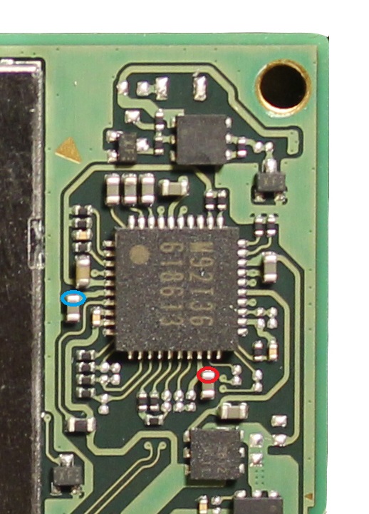
You can find those two Rails at the following locations. Disconnect battery/power and measure resistance to ground and post your readings
Great to hear that!
On the red i get around 3.7 kohms and on the blue 76.8 kohms
Hmm your readings are off, somethings affecting these rails. What do you get if you reverse probe polarity, red on ground, black on point/s?
Is the console unpatched? if yes does Hekate work?
Same thing with reversed polarity. The console is unpatched. In order to see if Hekate works I have to reassemble the switch, put the hekate file in a micro sd and launch the switch with a jig and tegrarcm right?
Correct 
If Hekate boots, take photos of the console info & sub tabs
Sadly tegrarcm doesn’t detect the switch. I think now I will reflux the usbc port , maybe the joints under the port are not well soldered.
Might be worth a try.
Though if the outer usb pins test fine relative to ground in diode or resistance and your not getting detection in tegrarcm with USB in either orientation, then the issue is likely elswhere.
You’ll hate me for saying it, but after ruling out the USB port I’d start with pulling the M9 IC and seeing if your resistance readings return to normal with it out of circuit, if not then do the same with BQ IC (though less likely it’s easy to remove& rule out) then if still not resolved, i’d pull Wifi IC as from memory (could be wrong) i believe 3V3PDR goes to it.
don’t worry ![]() Appreciate a lot your help
Appreciate a lot your help
Do you mean the resistance of those 2 caps?
↓
If so what values should I get?
Yeah
Red you should get approximately 10k and blue you should get approx 150k.
Though will forewarn, you might pull all the IC’s mentioned above and still find it doesn’t resolve it and the problem may be elsewhere…more often than not it’s the SoC ![]() sometimes PMIC
sometimes PMIC
Before pulling any IC’s though, if you disconnect the EMMC Module, do the resistance readings on those rails change at all? (caps red & blue)
No changes.
Without the m92 and usbc on red i get around 16 kohms and blue is acting weirdly sometimes i got just few ohms and other times around 170 kohms