That sounds possibly good for red at least (1V8PDR)
I’m operating from memory atm, but you might find the values comes good with another good M9 IC installed
Don’t worry about the other rail for now, measure again after replacing the M9 IC
That sounds possibly good for red at least (1V8PDR)
I’m operating from memory atm, but you might find the values comes good with another good M9 IC installed
Don’t worry about the other rail for now, measure again after replacing the M9 IC
Ok. Hopefully my friend has one m92 new, otherwise i’ll order one and I’ll let you known asap.
Don’t forget that a Switch will boot past the Nintendo logo to an error message if you remove the M92. Might be useful as an interim check. You’ll need to use a battery and either short a pad near the PMIC to ground (Pad 11, Cluster E - Testpads, switchbrew.org) , or plug in the power button flexi and start it that way.
Thank you Sheriff! I’ll keep that in mind
I finally managed to achieve the 16 kohms on red with m92 soldered. What can I do next?
Was really hoping for this rail to read approximately 10k relative to ground once your replacement M9 was installed.
Though tbh i don’t recall what the measurement should be on a known good board on this rail with M9 removed… even so, 16k is better than your measurements before and in contrast won’t have any negative affects on enables, pullups etc.
It’s also possible your still reading 16k due to a soldering issue on M9, if you can post a photo i may be able to confirm.
Either way, as Sheriff said, you should be able to test boot with a charged battery with it semi assembled regardless of M9 presence or of M9 install condition (provided no bridged pins/pads elsewhere)
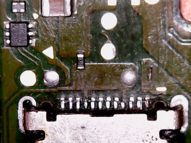
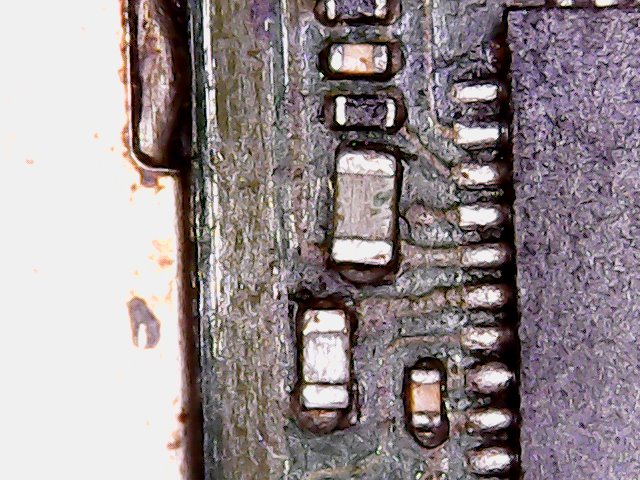
Here’s the photo
Now I’m going to try to power it up
So I made a few tests…
In all of them I get nothing on the screen.
I tried to power it on (1/2 times with Sheriff’s method) without:
Still no charging. May the problem be related with the screen or backlight?
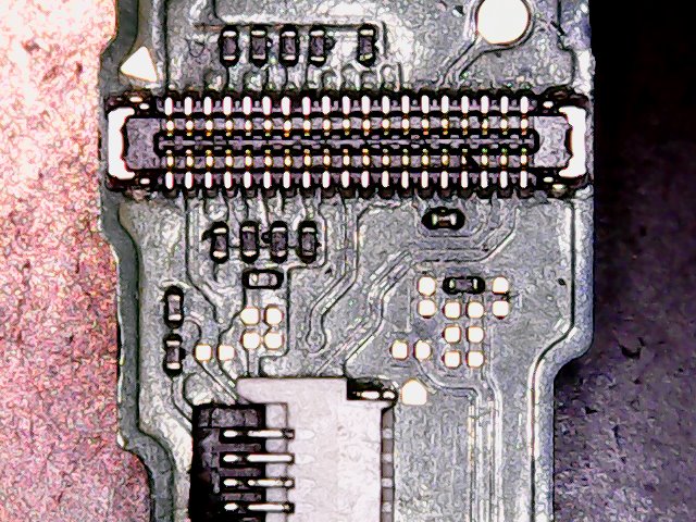
Also checked near the screen connector area… it seems all ok to me, even the connector.
I tried to put the mb in another switch(same model), still nothing on the screen.
Your soldering on M9 seems good,but it’s hard to tell because of the reflection, if you could get a snap more on angles, then could rule out.
Can you give me measurements at the previously mentioned points in both probe polarities relative to ground?
Unlikely to be the LCD or connector at fault if you’ve tested in another known good LCD/Assembly
btw having USBC cable/connector installed without M9 IC installed would make no difference, unless the pins were bent/bridged, or it’s plastic being burnt/scorched, in which case it would make a negative difference
Hopefully I think they’re ok ![]()
Red around 16 kohm and blue sometimes show me some Mohms and other times 180 kohms (it does the same even when I remove the cap)
Joints look good afaict. though i don’t like the discoloration on the caps on pins/pads 5/6, give them a good scrub with toothbrush and IPA
And the readings reversed probe polarity, red probe on ground? need to check junction is functioning prperly…not too worried about the intermittent Mohms readings and am just putting that down to a meter/ranging issue.
and the other rail in blue is probably fine, but reading reversed polarity?
Sorry for the late response.
With reversed polarity red is around 10 kohm  and blue around 20 kohms
Tried it right now.
Do you think they look better? The cap on pin 5 has some remains of a past uv mask that I couldn’t manage to clean properly.
Usually to test if switch charges i plug it to the 5v usb port of pc. Today when i tried it didn’t charge but windows recognised it as an unknown devices (I assume it turned on by itself) . I haven’t attached the screen sadly and after i tried it different times removing battery and usb c port it stopped showing on windows
Yeah somewhat ![]()
I’ve been trying to duplicate your measurments on 1V8PDR but can’t seem to do it, leave it with me and I’ll have another go at somepoint, your readings would seem to indicate something is open, that could mean something on this rail isn’t connected, meaning a pin/pad, a resistor etc.
Your USB not recognized message is typically associated with bad USB port, failed P13 and even a failed M9 IC, i think we can rule M9 IC out at this stage given that you have already replaced it.
Take it your not seeing any current draw when connected with USBC?
Not recently , the last time I was getting some amps was there.
After I replaced and resoldered usbc m92 and bq no more.
I may try to make some photos of the board hopefully you can find something
Yeah worth a try, though i should clarify… an open somewhere could constitute a part on the board that’s physically connected but in actuality is [blown/failed] open, making it harder to find
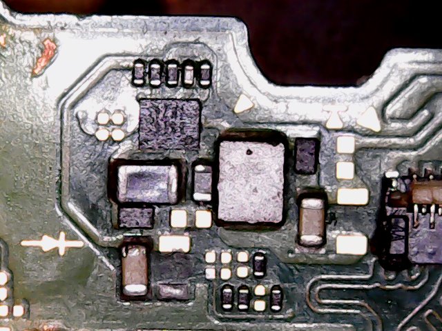
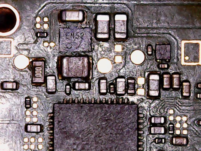
What a pity… Do you think maybe if i get a thermal cam I could pinpoint the problem? Today I tried locating some hot spots with IPA (turned it on with sheriff’s method) and it seems behind the wifi chip it was evaporating faster, after removing the emmc i found some caps(?)(some of them have a different color, I don’t know if they are really caps) shorted to ground
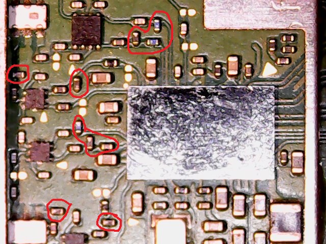
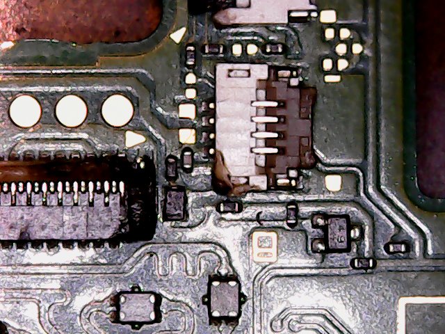
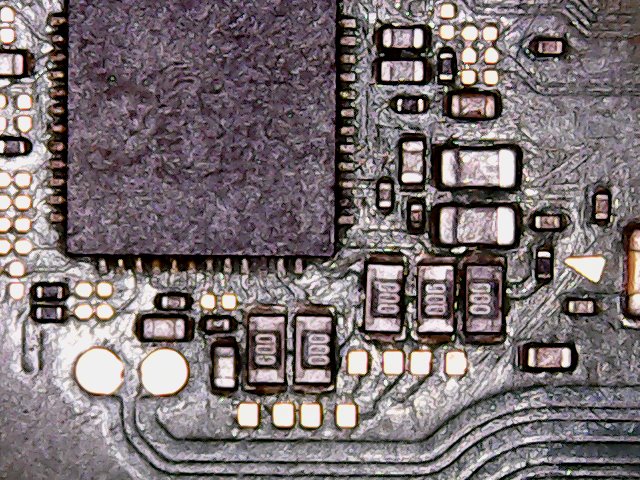
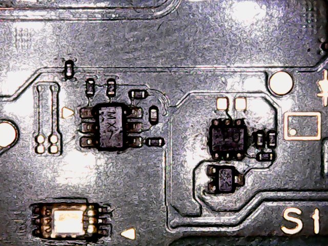
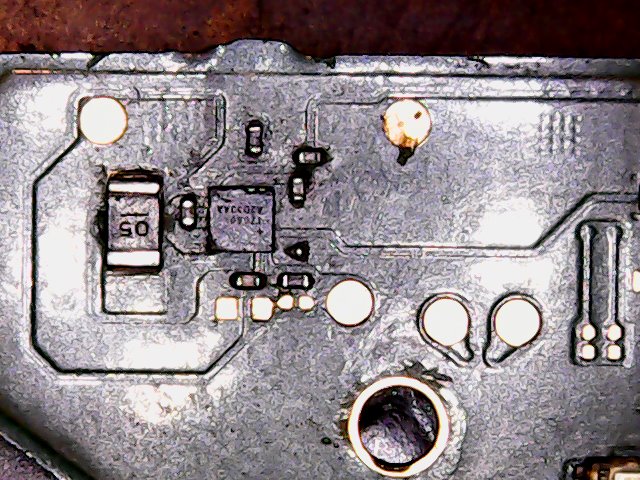
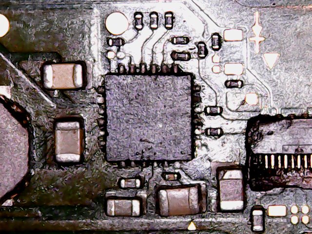
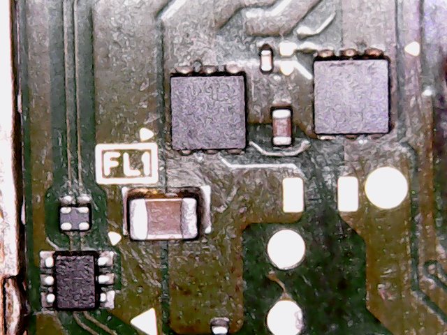
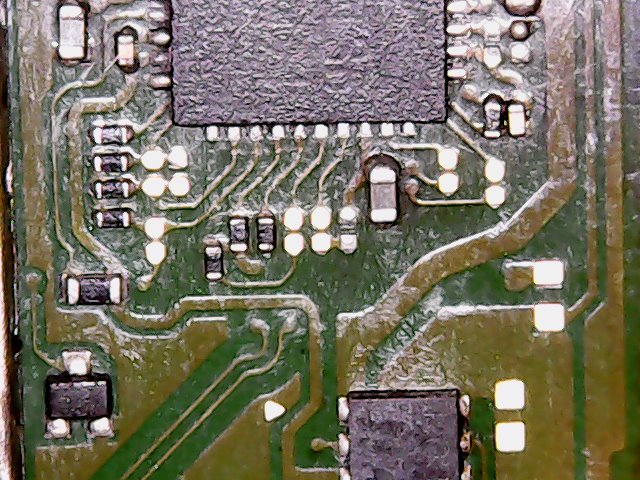
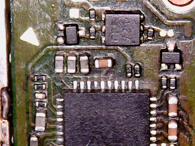
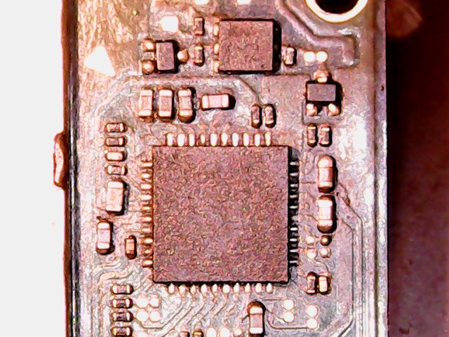
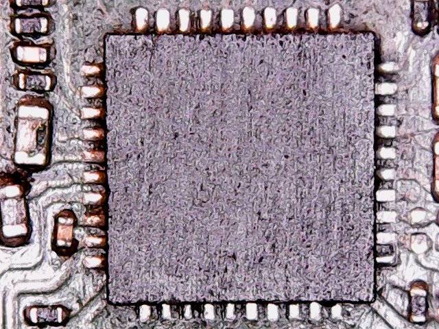
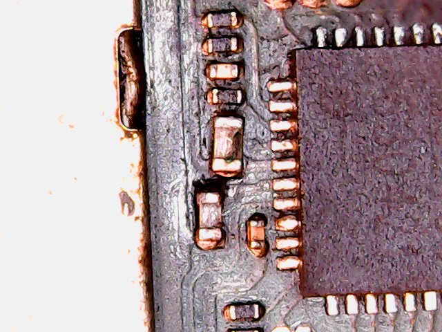
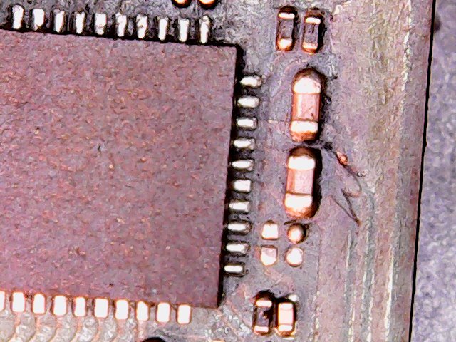
However… i made the photos… see if you can figure out something