Hello
I have done some Nintendo Switch Consoles, but this one is getting to me.
I am a few years from ‘retirement’ (yeah, I am a grandad!) and things are getting hectic - just to get on with daily repairs I do to get to the ‘retiring’ time!
I am no expert on consoles, but here it is.
It came with its charging port ‘snapped’ from its welded anchor plate.
I believe customer had previous problems and wiggled connector for a long time before it stopped charging - I wish he came earlier!
The connector itself was holding onto 8 side B [top] pads only, and both anchors on the front disappeared, then found one inside!
What I have done is:
First attempted fixing pads - all 15-16 of them!
It was working, but I noticed one in particular was naughty and I re-done it. Same problem.
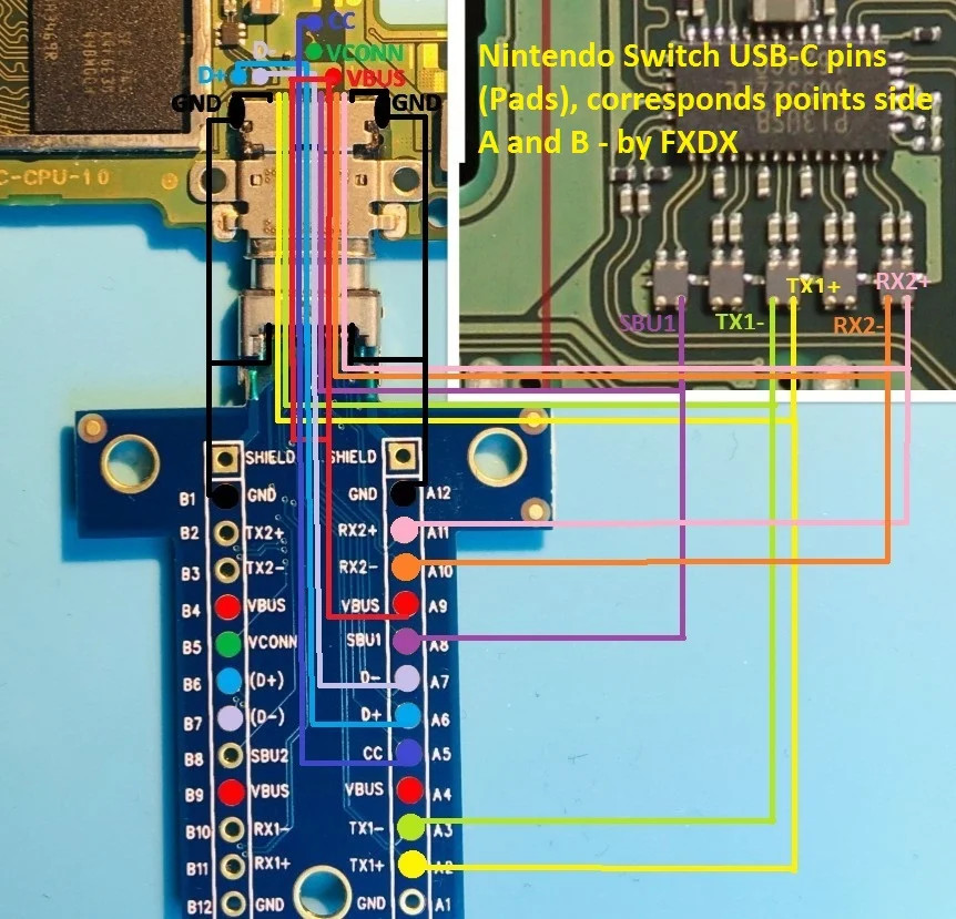
This time I approached the preferred method of wiring it, but not having enough knowledge and I not having a working one at the time, I browsed internet to find connecting points.
Anyway, found info [hopefully correct] and wired it.
Then replaced M92 + PI13 + BQ chips and now it does charge at 0.470A only on 5v - nothing drawn from 15v both sides. (a classic I believe but …)
I have taken diode arrays off and replaced M92 again + PI3 too
No change
I charged original battery and my new battery living it for quit a few hours.
I also taken ‘all’ Voltages and diode mode measurements twice [from internet pages I found] and checked for short ‘everywhere’ 7 times or more in the long run !!!
I wish I had a working oe to compare it with. Initially I had the cap under PI3 shorted and replaced it only because one side looked bad, but measuring cap it was not short and also replaced PI3 - this is another weird one, as after taken the cap off and re-measured there was NO short - I am thinking maybe one anchor bit reached it.
I did measure M92 switching ports - so it does detect them and I also used Freeze spray on both sides and changing connection to port to see what was happening.
Nothing particular and I could only see the 2x Mosfets in parallel under M92 (not the top one) getting ‘slightly’ warmer when switched - denoting they are switching too - also measured voltage - as far as I understand it.
Bear in mind it does boot normally - always, with on-off or by connecting the ‘detected’ side of the cable
I had it for a while now and no idea what to do next - I am stuck and customer waiting, although I believe he must have another one. I am my brain full of Nintendo confusion now.
My soldering of chips are fine and I believe chips are OK - believe me and I do not understand why it does not charge on other side.
One thing I do not know, can this type of behaviour ‘also’ have anything to do with the CPU - just asking.
Anybody ever had ‘this’ particular behaviour and can really help?
I am getting tired of it now.
Thanks in advance
M
PS I posted on Badcaps forum too, but I guess guys are busy and it is the weekend
I am not often on forums really … just thought someone here might have had a similar experience and maybe solved it.
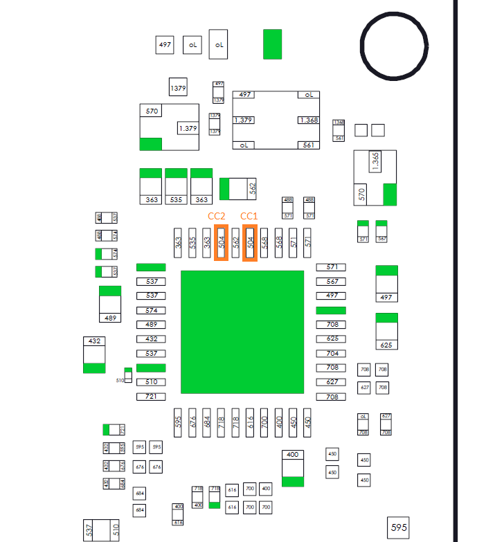
If only one side at charging is detected, there is a problem with the both cc lines, which tells the m92t36 which way around the charging cable is plugged in.
During booting the Swich, the amps should drop from ~0.45 to 0 and then jump up to ~1.45 fast charging. But it will drop down in case the battery is close to full.
For 15V charging, charger and m92t36 must talk to each other first. So there might be a problem with the both data (D+/-) lines.
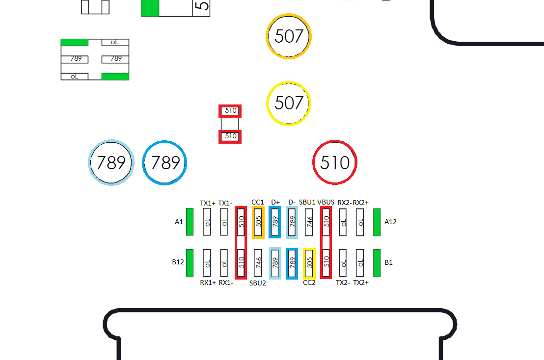
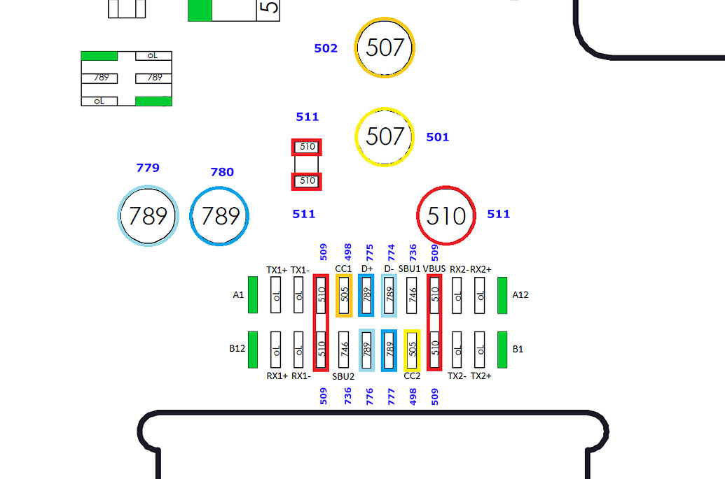
You can check the activity of the cc lines at the test points (yellow/ocher). One of them should be high depending on the orientation of the plug.
At the data lines testpoints (light blue/blue) you can check for continuity to the usb c port and for aprox. similar diode mode readings. If there is a problem with this lines the readings are different to each other or ‘oL’ or shorted.
Hi
Thank you for taking the time to reply - appreciated.
Although mostly repair what I can without schematics, I am the type of technician used to diagrams (old style) and these days manufacturers are doing their best to stop us repairing or the consumer as well.
Although I am sure chips/etc. are connected, I will certainly re-check - as I am the type that checks and recheck.
Never know you find something you missed.
The other day I left it overnight charging the battery that is fit in the Switch and it did charge to 4.1-4.2.
The morning after I disconnected and re-connected and noticed it did just that [since it does boot normally] - i.e. just what you said: During booting the Switch, the amps should drop from ~0.45 to 0 and then jump up to ~1.45 fast charging. But it will drop down in case the battery is close to full.
Will do that and I also have been reading a few threads as well - very informative.
Just trying to serve my locals and get one for the next few years …then it might become a home hobby!
Do I need to get an original PSU [15v 2.6A] ?
I have a non original one with attaches a USB-c female to female, so I can connect it to my Ammeter and see what happens.
One of these MP780426 as ammeter - works well up to 24v - so I can cover Laptops if needed.
I also do not have a original dock and do not wish to test it using a non original one, I read there is a danger it can mess up the Switch!
I would recommend to buy an original charger and dock if you want to do more repairs on Nintendo Switches.
It would be helpfull to test 15V charging and dock mode.
The pmics from Switch, charger and dock have to talk to each other to deliver the right voltages. If there is a missmatch in communication, the charger might only delivers 5V or even nothing or in worse case because of an other pmic type, send 9v on the cc lines, which could blow the power management ics from the Switch or/and dock.
…and I have just re-done a short check using multimeter buzzer over the whole board - no shorts.
I also re-fit board on Nintendo with all its bits connected and seems to work fine, but the 470mA on side only charging ok.
Going home in 10min.
will be home tomorrow, got to do some yearly stock checking file… pffff
Interessting one…
Do you have the possibilty with a usb-c breakout board to check if the both cc lines have continuity from the usb c plug contacts to their pads at the m92t36?
Alternativ you can check the voltage on the cc testpoints and the both pads at the m92t36. You should get a reading (~0,5V @ 5V) on one of the both cc lines depending on which way around the charger is plugged in.
I know, I am in the… why is this happening time!
I was just online now doing some work and saw your reply.
I did check and re-checked using a break-out USB-c board from board to the actual end of the wiring - i.e. the wiring I did on the USB-c plug.
All fine, although sometime ago - strangely - I did find pins … I am not there now but I think they were Side B 'top of board - these 2 pins were ‘not’ connected from the pin on the board to the filter on PI3USB chip! Therefore the 2x PCB internal joints were somewhere disconnected!
Weird but true.
So, I did add 2 more wires from the top side B pins to the filters - no change!
All pins measure OK - I am just on the 'what the heck it is happening.
I mean I have been on Electronics for many years, i just do not know Switch that much, but I have learned a lot thanks to this one.
I think the 2x pins were RX2- and +
I also check up to the actual chips pins.
Will do that, I do not remember if I did, but I remember I did find 5v changing on two pins when switching insertion of plug.
Pity, as this Switch works fine now!
I communicated via email with customer to let him know, I have not disappeared - I had it a long time - very rare for me.
I care for my customers.
It must be something right in front of me and I do not see it - it must be cc1/2 on M92, as it is the chip that decides the next move based on insertion.
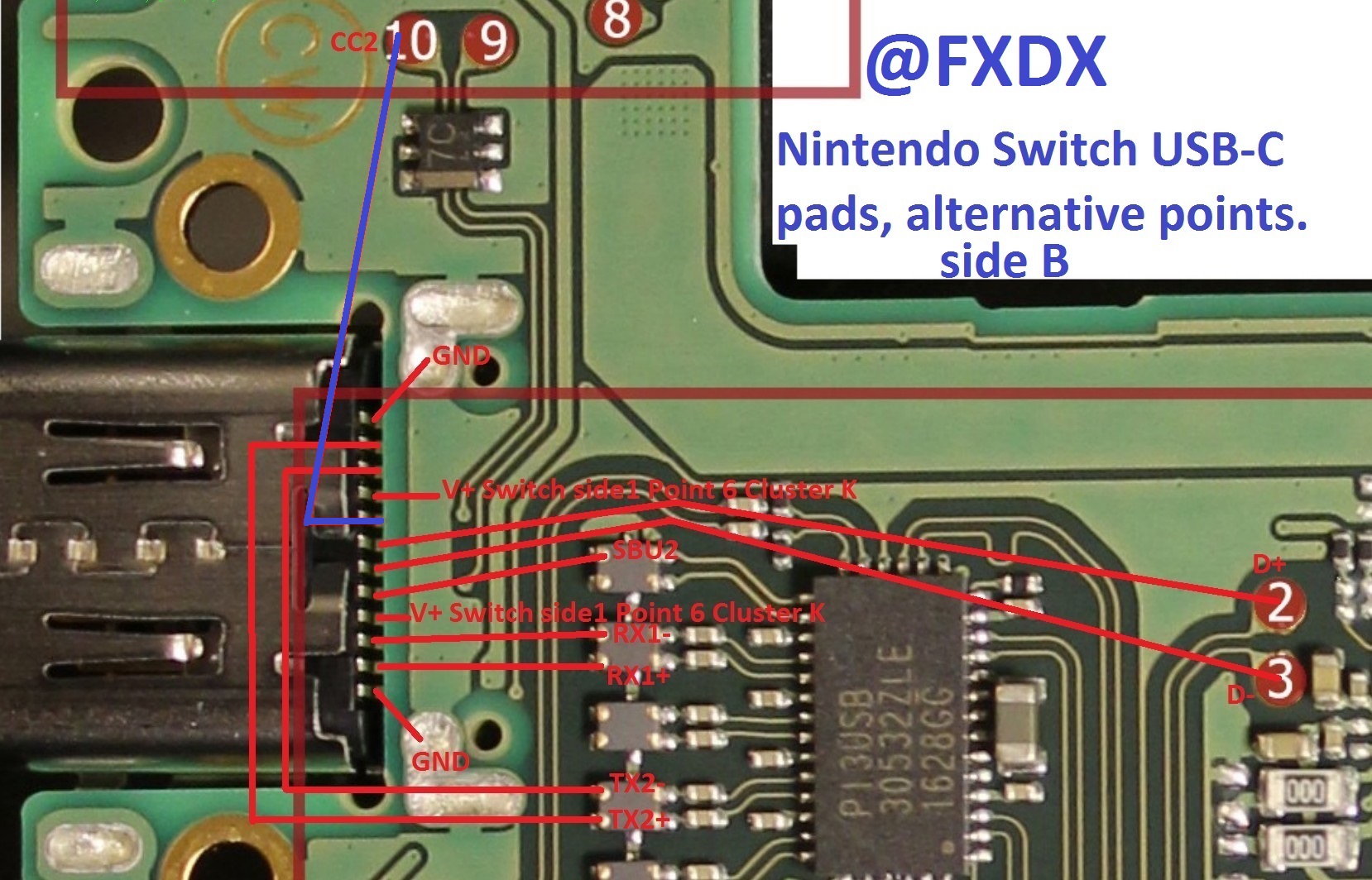
I just checked CC1 on USB-c side A (bottom) and CC2 side B.
Well side B is OK, but not side A and I am now more confused by the USB-c wiring diagram which sets CC1 connected to first pin on first filter under PI3USB and it also calls it SBU2 - it other way round!
I wish I had a working Switch, as I would have done my own wiring diagram - as I normally do in these cases and then share a correct one! I believe they mixed up side a with B!
I wasted all this time and the diagram is wrong? I have already seen somewhere another wrong side a/b references. People rush too much and do not chek. This time I trusted source, but I believe it is wrong.